

patent · US4282858A
Solar energy system and method
11 August 1981
Text
Page 1bibliographic recordscan →
United States Patent (19)
Bowers, Jr.
54 SOLAR ENERGY SYSTEMAND METHOD
75 Inventor: Richard S. Bowers, Jr., Lebanon, Pa.
73 Assignee: Bowers Industries, Inc., Cleona, Pa.
Int. Cl. ................................................. F24J 3/02 52 U.S. Cl. .................................... 126/425; 126/437;
Re. 25,242 9/1962 Toulmin ............................... 126/439 294,117 2/1884 Calver ...... ... 126/439 1,969,839 8/1934 Goddard .............................. 126/439 3,051,038 8/1962 Duke .................................... 126/439 3,869,119 3/1975 Cummings ........................... 126/440 3,985,118 10/1976 Bard ..................................... 126/440
4,002,031 1/1977 Bell ...................................... 126/440 4,026,267 5/1977 Coleman .. ... 26/449 4,037,652 7/1977 Brugger ...... ... 126/437 4,068,474 1/1978 Dimitroff ..... ... 126/440 4,201,197 6/1980 Disner ................................. 26/440 Primary Examiner-Daniel J. O'Connor
Attorney, Agent, or Firm-L. Lawton Rogers, III
A solar energy fluid heating system and method wherein sunlight is focused on the one end of a number of light pipes and directed by the other ends of the light pipes onto a heat conductive surface at the bottom of a number of tubes within a fluid storage tank. Each of the tubes within the tank is apertured adjacent to the lower end thereof and open at the other end thereof to permit fluid circulation within the tank. The tubes may be entirely of heat conducting material to accomplish fluid heating over an increased portion of the tubes.
8 Claims, 5 Drawing Figures
Drawings
Page 2drawing sheetscan →
Page 3drawing sheetscan →
Page 4scan →
The solar energy collecting array 10 will include a
SOLAR ENERGY SYSTEM AND METHOD plurality of collectors 12 mounted in rows and columns. The entire array 10 may be positioned by suitable con
BACKGROUND OF THE INVENTION ventional electromechanical means (not shown) mounted by the supporting structure 18 and operative
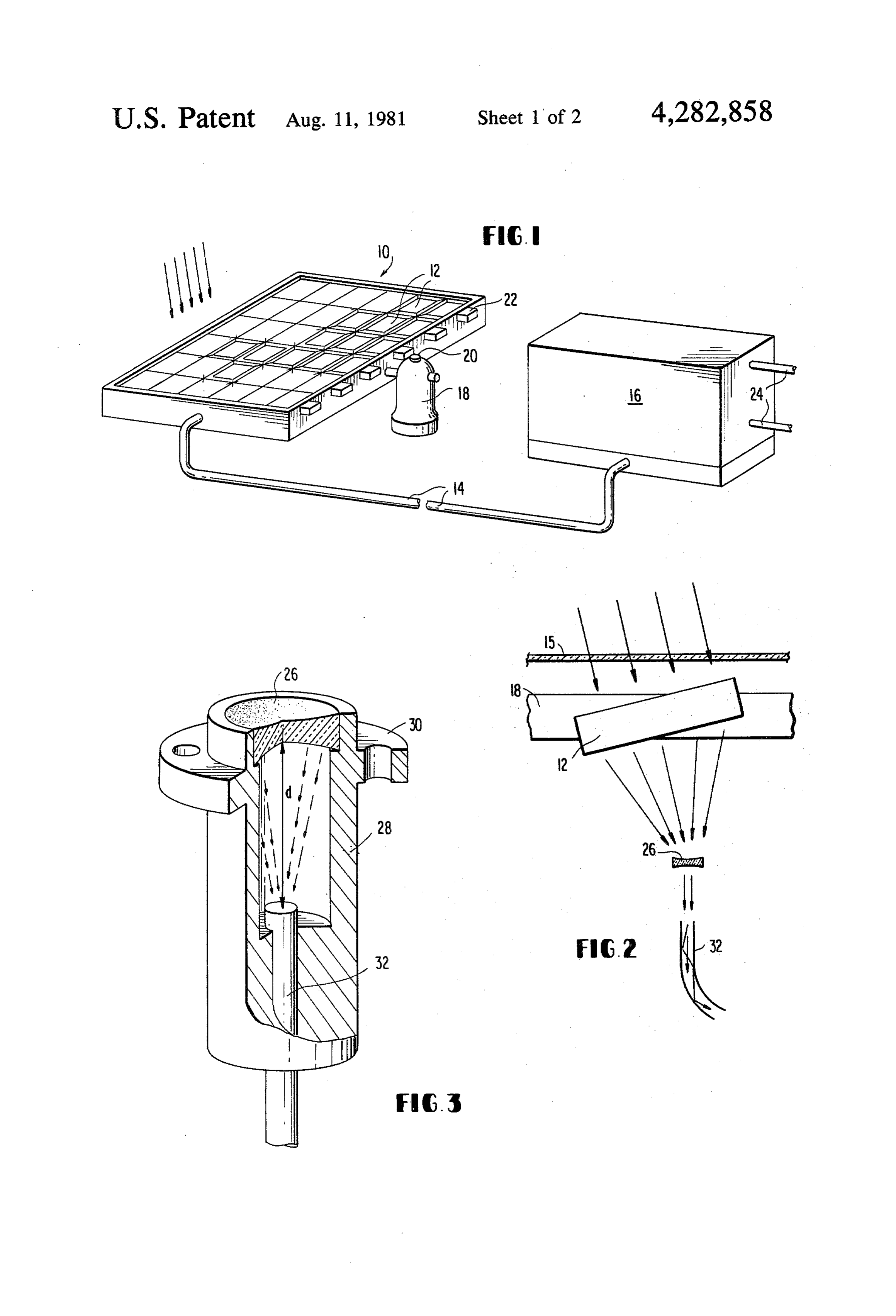
Solar energy heating systems are becoming increas in a well known manner under the direction of one or ingly popular due to the expense of fossil fuels, the more solar sensors 20 to track the sun. Alternatively, maintenance of the systems for the combustion of fossil entire rows of the solar collectors 12 may be positioned fuel, and the atmospheric pollution which results from as a unit under the control of suitable conventional such combustion. Such solar energy heating systems 10 sensing and tracking means 22. In all instances, maxi must generally be located in direct sunlight and gener mum efficiency is obtained by the proper orientation of ally include a lens system for focusing sunlight incident the individual collectors 12 with respect to the sunlight thereon into the fluid to be heated. This requires the incident thereon.
location of fluid conduits and/or fluid tanks on the roofs The sunlight incident on each of the solar collectors of buildings, etc. creating additional expense in the fluid 15 12 is focused on one end of a light pipe which may be of handling system and in the construction of the support a suitable conventional type internally reflective of light ing structure. conveyed therein. These light pipes or fiber optic ele Additionally, conventional solar heating systems are ments may be flexible to accommodate movement of required for maximum efficiency to track the sun, and the solar collectors in tracking the sun and may be bun the increased weight of the fluid handling system repre 20 died together to convey collected sunlight to the fluid sents a substantial increase in the size, weight and ex storage tank 16.
pense of the tracking mechanism as a result of the loca The fluid storage tank 16 is desirably of the type tion of the fluid handling system in proximity to the hereafter described in detail in connection with FIG. 3. sunlight collectors. and may include a plurality of heating elements each It is an object of the present invention to obviate 25 responsive to sunlight conveyed through the fiber optic many of the disadvantages associated with generally system 14 to heat the fluid in contact therewith. The known solar heating systems and to provide a novel uses of the fluid heated in the tank may be conventional, method and apparatus for heating a fluid by solar en and appropriate fluid influx and egress systems 24 may ergy. be provided. - It is another object of the present invention to pro 30 With reference to FIG. 2, the solar collector 12 may vide a novel method and heating system in which the be positioned with respect to the sunlight by rotation fluid to be heated is remote from the solar collectors. beneath a glass cover 15 within the supporting frame 18. Is is a further object of the present invention to pro The lens 12 may be a square Fresnel lens serving to vide a novel method and solar heating system in which collect and focus the sunlight onto a bio-concave lens 26 the fluid to be heated may be located out of the inci 35 which in turn directs the sunlight into a light pipe 32. dence of sunlight. With reference to FIG. 3, the embodiment of a solar It is yet a further object of the present invention to collector is illustrated. As shown in FIG. 3, the collec provide a novel method and system for internal light tor may comprise a lens 26 mounted within a generally 1ng. cylindrical housing 28 having a flange 30 apertured for These and many other objects and advantages of the 40 mounting purposes. Axially located with respect to the present invention will be apparent from the claims and lens 26 is one end of a light pipe 32 which may be ad from the following detailed description of a preferred justed by any suitable conventional means to conform embodiment when read in conjunction with the ap the distanced between the end of the light pipe 32 and pended drawings. the surface of the lens 26 to the focal length of the lens. 45 The means for holding the light pipe 32 at the correct
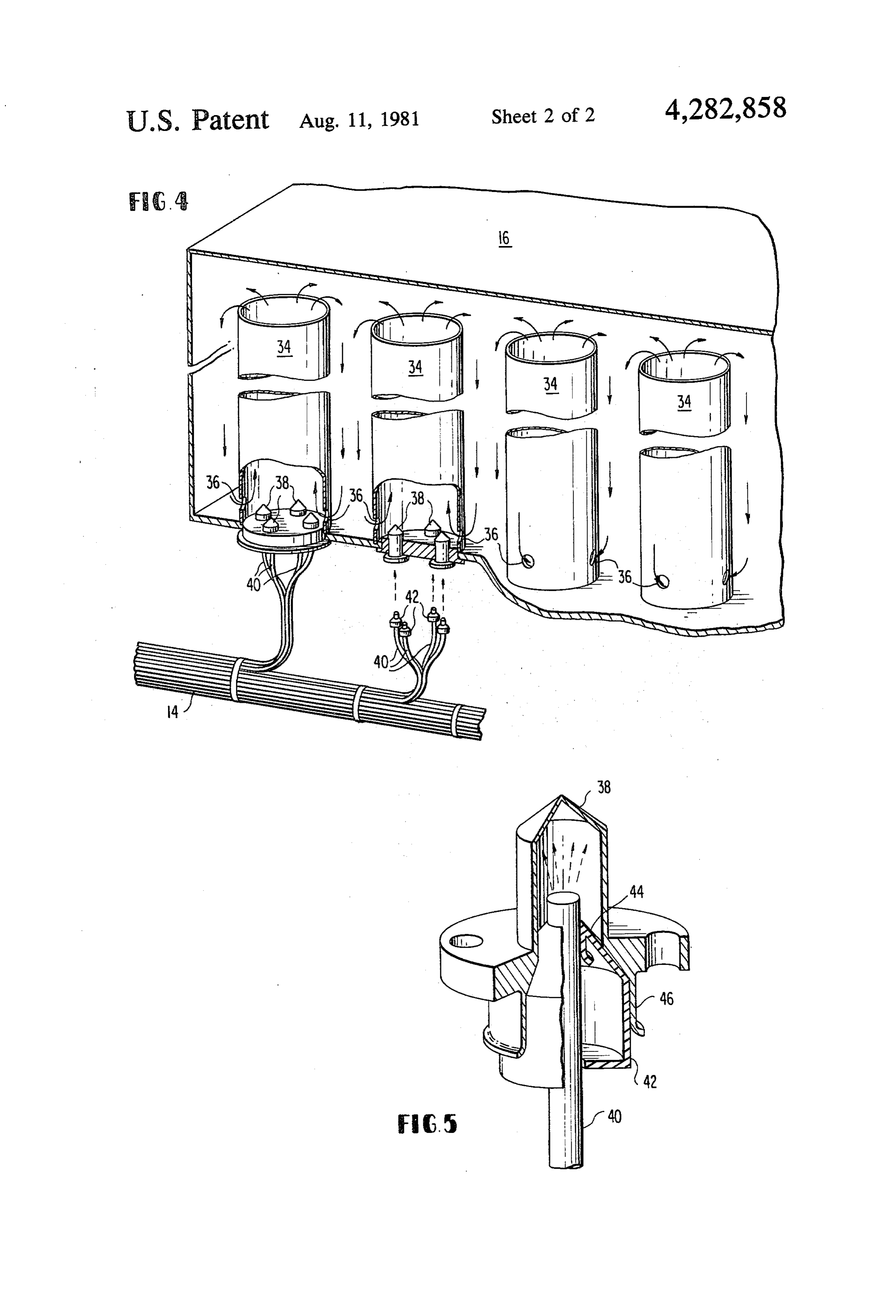
THE DRAWINGS position may be any suitable conventional means and FIG. 1 is a pictorial representation of one embodi may be of the type hereafter described in more detail in ment of the present invention; connection with FIG. 5.
FIG. 2 is a schematic diagram illustrating the opera The lens unit is desirably positioned at the focal point tion of a lens system useful in the present invention; 50 at each of the solar collectors 12 of FIG. 1. By way of FIG. 3 is an elevation in partial section of one em example, each of the solar collectors 12 may include a bodiment of the solar collector of the present invention; 12 inch square Fresnal lens having a focal length of FIG. 4 is a pictorial representation in partial section approximately 7 inches. The purpose of the Fresnal lens of one embodiment of the fluid storage tank of the pres is to magnify and to concentrate the solar energy onto ent invention; and 55 the lens 26 which may be of the bio-concave type to FIG. 5 is an elevation in partial section of one em direct the collected solar energy into the light pipe 32. bodiment of the fluid heating elements illustrated in Again by way of example, the collected element illus FIG, 4. trated in FIG.3 may be approximately 1 inch in diame ter and approximately 2 inches in length.
DESCRIPTION OF THE PREFERRED 60 The entire system of Fresnal lenses may be protected EMBODIMENT from the elements by a sheet of tempered glass or other With reference now to the figures where like numeri solar energy transparent material. Maintenance is also simplified and a planar surface provided to facilitate cal designations have been accorded like elements in the cleaning.
interest of clarity, and with particular reference to FIG.
1, the invention comprises a solar energy collecting 65 With reference to FIG. 4, the fluid storage tank 16 of array 10, the individual solar collectors 12 of which are FIG. 1 may include any suitable conventional tank collected by means of fibre optic or a light pipe system apertured at the botton to receive rows and columns of heat transfer tube 34. As shown in FIG. 4, each of the 14 to a fluid storage tank 16.
Page 5scan →
heat transfer tubes 34 may be open at the upper end and 1. A solar energy heating system comprising: provided with an aperture 36 at the lower end thereof. a plurality of solar collectors each adapted for orien In this way, fluid heated within the tube may rise in the tation toward the sun and each including a lens tube and circulate. The lower end of the tubes 34 is element for focusing sunlight; closed and is desirably formed into one or more pure 5 a fluid storage tank including a plurality of heat trans metal shapes 38. The bottom of each of the tubes 34 is fer tubes, at least the lower end of said tubes being desirably of a heat conducting material whereby the of a heat conductor substance, being open at the direction of sunlight thereon will heat the material and upper end to permit the egress of relatively heated thus the fluid in contact therewith. Copper has been fluid therefrom, being closed at the lower end, and found to be a suitable material. With continued refer being apertured adjacent the lower end to permit ence to FIG. 4, the fiber optic system 14 of FIG. 1 may the entrance of relatively cooled fluid into the tube be separated into individual light pipes 40, each con adjacent the closed end; and nected to one of the heat transfer tubes. Any suitable fiber optic means for connecting each of said solar conventional connector 42 may be utilized to hold the collectors to the closed end of one of said heat individual light pipes 40 in position to direct sunlight transfer tubes, said means including means at one existing therefrom against the lower surface of the heat 15 end for positioning said one end to receive sunlight conduction cones 38. focused by one of said plurality of solar collectors One embodiment of the light pipe connector 42 is and means at the other end for positioning said illustrated in greater detail in FIG. 5 where, for simplic other end to direct sunlight against the closed end ity's sake, only one of the metallic heating elements 38 of one of said plurality of heat transfer tubes and is illustrated. As shown in FIG. 5, the means for adjust- 20 thereby heat fluid within said storage tank. ing the position of the light pipe 40 may comprise a 2. The system of claim 1 wherein substantially all of metallic sleeve adapted to resiliantly grip the light pipe each of said heat transfer tubes is heat conducting 40 and to be in turn gripped in any suitable conventional whereby heat generated by the direction of sunlight manner by the lower end 46 of the conical heating ele against the closed end of the tube is conducted away ment 38. 25 from the closed end thereof.
It is desirable that the heating elements 38 be rigid in 3. The system of claim 1 wherein said positioning construction and adapted to be securely fastened to the means at the solar collector end of said fiber optic tank inasmuch as the upper surface thereof may form means includes means for varying the distance between the bottom of the fluid storage tank. While it is desirable the end of said fiber optic means and said lens element. that the rapid connect/disconnect light pipe 40 posi 4. The system of claim 1 wherein said positioning tioning means 44 be securely positioned with respect to means at the fluid storage tank end of said fiber optic the heating element 38, fluid tight integrity is not re means includes quick connect/disconnect means. quired. 5. The system of claim 1 wherein said plurality of LIGHTING SYSTEM solar collectors are protected from the elements by a cover transparent to sunlight.
The system of the present invention has utility on an 35 6. The system of claim 1 including means for orient internal lighting system. In such a system, the light from ing said plurality of solar collectors responsively to the the fiber optic system 14 of FIG. 1 may be used to position of the sun, said means including a sensor and an illuminate with natural light internal spaces within a electromagnetic drive unit.
structure which is windowless or otherwise devoid of 7. The system of claim 1 wherein each of said solar natural light. In systems of this type, an opaque lens may 40 collectors includes a relatively large diameter Fresnel be used to defuse the light exiting the fiber optic system lens and a relatively small diameter bio-concave lens, in a well known manner. the bio-concave lens being positioned at the approxi ADVANTAGES AND SCOPE OF INVENTION mate focal point of the Fresnel lens. 8. The system of claim 1 wherein substantially all of
From the foregoing, it is apparent that the method 45 each of said heat transfer tubes is heat conducting and solar energy heating system of the present invention whereby heat generated by the direction of sunlight is advantageous with respect to generally known solar against the closed end of the tube is conducted away heating systems. More particularly, the unique lens from the closed end thereof;
construction achieves great efficiency in the collection wherein said positioning means at the solar collector of solar energy and the utilization of a flexible fiber 50 end of said fiber optic means includes means for optic system to convey this energy to a remote location varying the distance between the end of said fiber for fluid heating obviates the necessity for location of optic means and said lens element; the fluid handling system adjacent the solar collectors. wherein said positioning means at the fluid storage Significant savings may thus be obtained and the con tank end of said fiber optic means includes quick struction of the solar arrays supporting structure and in 55 connect/disconnect means; the cost of the fluid handling system. wherein said plurality of solar collectors are pro In use as a lighting system, many of the same advan tected from the elements by a cover substantially tages are obtained and natural light may effeciently be transparent to sunlight;
conveyed to internal spaces. wherein said plurality of solar collectors including The principles, preferred embodiments and modes of means for orienting said plurality of solar collec operation of the present invention have been described 60 tors responsively to the position of the sun, said in the foregoing specification. The invention which is means including a sensor and an electromagnetic intended to be protected herein, however, is not to be drive unit; and construed as limited to the particular forms disclosed, wherein each of said solar collectors includes a rela since these are to be regarded as illustrative rather than tively large diameter Fresnel lens and a relatively restrictive. Variations and changes may be made by 65 small ciameter bio-concave lens, the bio-concave those skilled in the art without departing from the spirit lens being positioned at a point approaching the of the invention. focal point of the Fresnel lens.se What is claimed: : ck ck k
Provenance
- Collection
- Patents citing this work
- Pages
- 5
- Method
- pdftotext (the PDF's own text layer) + pdftoppm 300dpi page scans
- Patent office record
- patents.google.com →
- Source
- Google Patents citing-documents table
- Assignee
- Bowers Industries, Inc.
- Published
- 1981-08-11
- Transcribed from
- patentimages.storage.googleapis.com →