

patent · US4282862A
Thin-line collectors
11 August 1981
Text
Page 1bibliographic recordscan →
() is 4 a. er
United States Patent (19)
Soleau
THIN-LINE COLLECTORS
Inventor: Bertrand S. Soleau, 4203 Kincaid Ct., Chantilly, Va. 22021
51 Int. Cl. ................................................. F24, 3/02 U.S. C. .................................... 126/439; 126/440;
3,471,221 10/1969 Seeger .................................. 350/263 4,074,704 2/1978 Gellert ................................. 26/440
FOREIGN PATENT DOCUMENTS
Primary Examiner-James C. Yeung
Attorney, Agent, or Firm-Robert W. Carlson
Thin-line solar energy collectors are disclosed. The solar collectors of this invention function by internally redirecting incident light to the periphery of the collec tor where it is absorbed by a heat transfer fluid. This is accomplished by reducing the angular dispersion of the incident light with a high index of refraction glass, re flecting the light from wedge shaped surfaces and then transporting the light to the periphery of the collector module via total internal reflection. A typical collector is made up of a plurality of glass modules mounted in a frame through which the heat transfer fluid is circu lated. Each individual glass module is a collector de signed in accordance with this invention and is typically inches thick by 1 inches wide by 3 feet long.
7 Claims, 3 Drawing Figures
Drawings
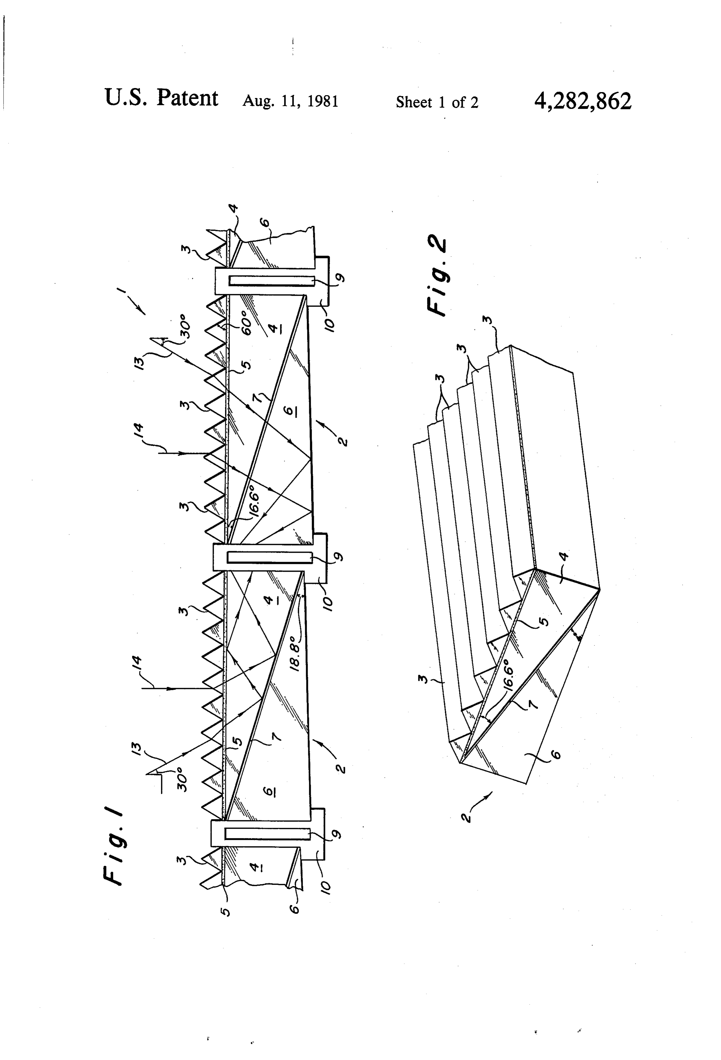
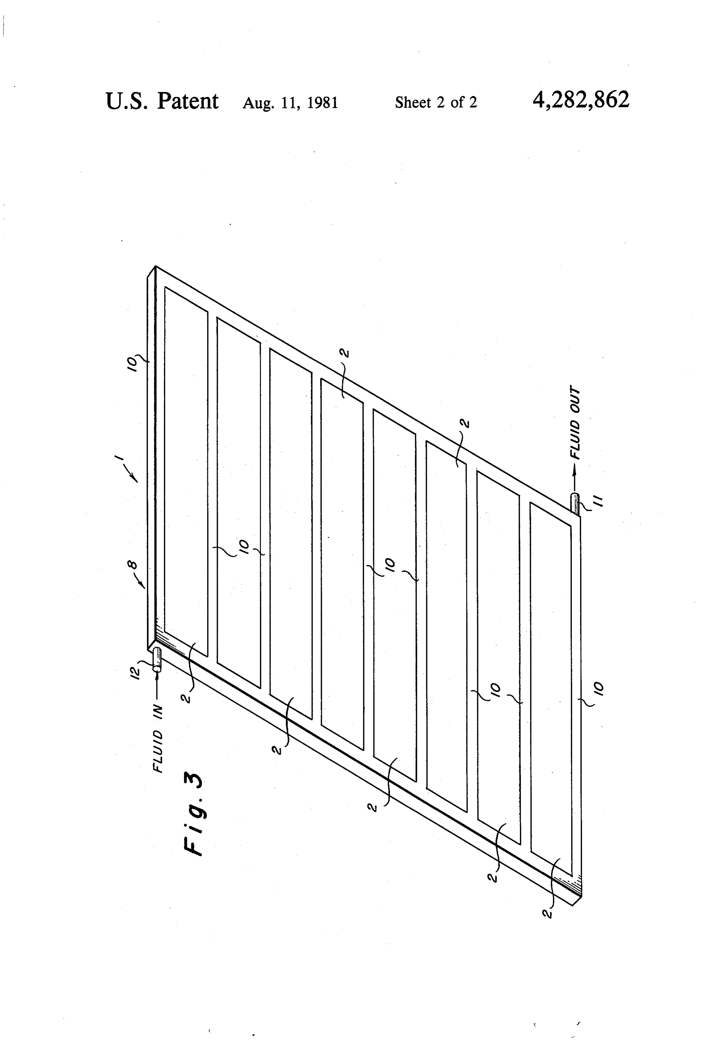
FIG. 2 is a planar view part of a preferred embodi
Page 2drawing sheetscan →
Page 3drawing sheetscan →
Page 4scan →
FIG. 2 is a planar view part of a preferred embodi
THIN-LENE COLLECTORS ment of the individual modules or collectors of this invention; and
BACKGROUND OF THE INVENTION FIG. 3 shows a solar collector constructed in accor This invention relates to solar collectors and more 5 dance with a preferred embodiment of this invention. particularly to a thin-line-non-focusing concentrating DETAILED DESCRIPTION OF THE solar collector. INVENTION
Flat plat solar collectors of numerous different de signs are known in the art. These prior art devices gen 10 thisReferring to FIGS. 1 and 2, the solar collector 1 of invention is made up of a plurality of glass modules erally include one or more plates of glass or plastic that or collectors 2. Only two complete modules or collec are mounted in a frame. The collectors are generally tors 2 are shown in FIG. 1. As shown in FIGS. 1 and 2, heat insulated to prevent heat losses. As a result the each module or collector 2 includes a plurality of glass prior art flat plate solar collectors are large bulky de wedges 3. The wedges 3 form the top surface of each vices. 15 collector or module 2 and have a high index of refrac Another type of prior art solar collectors are the tion. For example an index of approximately 1.8. concentrating type collectors that use some method of The glass wedges 3 are glued to a triangular shaped focusing the solar energy. For example, one type of piece of glass 4 by means of a glass cement 5 having an prior art focusing collectors uses a parabola to focus the index of approximately 1.4. The triangular shaped piece solar energy. 20 of glass 4 also has a high index of refraction, for example This invention provides a concentrating solar collec an index of approximately 2.
tor without focusing. Further, the solar collector of the The triangular shaped piece of glass 4 is cemented to invention is made up of a plurality of individual modules a second triangular shaped piece of glass 6 by means of or collectors that are small in size, light weight and 25 matelya glass cement having an index of refraction of approxi therefore easily transported. 1.4. The triangular shaped piece of glass 6 also The thin-line collectors of this invention provide a has a high index of refraction. For example an index of concentration ratio of about 2:1, do not require glazing approximately
Instead of being cemented along their entire mating or back insulation, hermetic sealing is not required, and surfaces, triangular shaped pieces of glass 5 and 6 can be tracking of the sun is not required. In addition, the solar 30 cemented along their mating edges with remaining collectors of this invention provide good efficiency due space between the mating surface being a dead air to minimum heat loss areas, the efficiency is relatively space.
independent of ambient temperature, and are suitable Each of the modules or collectors 2 are mounted in a for both thermal and photovoltaic applications. frame 8 (FIG. 3), having the channels 9 which carry the SUMMARY OF THE INVENTION 35 heat transfer fluid not shown.
Referring to FIG. 3, a complete collector 1 is made
The solar collector of this invention is a thin-line, up of a plurality of individual modules or collectors 2 non-focusing, concentrating collector. The collector is mounted in the frame 8 which has a plurality of the arms made up of a plurality of individual collectors or glass 10 which contain the heat transfer fluid carrying chan modules that are mounted in a frame through which the 40 nels 9. The cold fluid enters the frame 8 at the inlet 11 heat transfer fluid is circulated. and the heated fluid flows out of the outlet 12. The In the preferred embodiment, the individual glass collector 1 shown in FIG.3 represents an example of a modules include a wedge of glass having an index of collector constructed in accordance with this invention. refraction. The wedges are connected to a generally More or less individual modules 2 may be provided. In triangular shaped piece of glass also having a high index 45 addition, a plurality of the modules 2 may be arranged of refraction and this triangular shaped piece of glass is end to end as well as side to side as shown or a plurality cemented to another generally triangular shaped piece of collectors 1 may be provided in a given application. of glass also having a high index of refraction. Referring to FIG. 1, solar energy enters the individ These individual modules are relatively small in size. 50 ual modules or collectors at the wedges 3 since these For example, each module will typically be inches wedges form the top of the collector. Each individual thick, 1 inches wide and 3 feet long. These dimensions collector or module 2 has an acceptance angle of 30 are given by way of example and are not to be consid 13. which is indicated by the angle associated with the lines ered limiting or critical dimensions. Each module is As shown The lines 13 indicate solar radiation at a 30° angle. mounted in a frame through which a heat transfer fluid 55 externally toin the
FIG. 1, this radiation is totally reflected is circulated. Each module accepts the energy incident 9. The sides of thearms arms 10 and heats the fluid in channels 10 adjacent the modules 2 and upon it and delivers it to the fluid around its edges. The is of a good heat conducting module is so designed that the energy is totally inter heat transfer to the fluid. Thematerial top and to provide good bottoms of the nally reflected to the periphery of the module. arms 10 are preferably made of a heat insulating mate BRIEF DESCRIPTION OF THE DRAWING 60 rial. The lines or arrows 14 in FIG. 1 indicate vertically incident radiation and shown how this radiation is to
A full and complete understanding of the invention tally reflected internally.
can be obtained from the following detailed description While FIGS. 1, 2 and 3 show a thermal collector, the when read in conjunction with the annexed drawing in collector of this invention can also be used in photovol which: 65 taic applications. For such applications, the arms 10 FIG. 1 shows, in cross-section, part of a solar collec would have a plurality of solar cells mounted on their tor constructed in accordance with a preferred embodi outside surfaces adjacent the collectors or modules 2. ment of this invention and Wires would be brought out through the arms to trans 5 port the generated electricity to the load being powered module to a different form of energy comprises a frame by the solar cells. having heat transfer fluid carry channels and wherein From the foregoing description, it should be apparent said solar energy is converted to heat energy. that the solar collector of this invention provides a 3. A solar collector as defined in claim 2 wherein said non-focusing concentrating Solar collector that does not 5 plurality of glass wedges have an index of refraction of have to follow the sun. A concentration ratio of approx approximately 1.8, said first triangular piece of glass has imately 2:1 is obtained. Total internal reflection is ob an index of refraction of approximately 2 and said sec tained in the individual collectors or modules 2. Fur ond triangular shaped piece of glass has an index of ther, the collector of this invention provides many ad refraction of approximately 2.
vantages over conventional flat plate collectors such as 10 4. A solar collector as defined in claim 1 wherein said reduction in size and weight, higher concentration collector includes a plurality of said glass modules and without following the sun and ease of construction wherein said module is surrounded by said means for among others. converting solar energy.
While the invention has been described with refer 5. A solar collector as defined in claim 4 wherein each ence to a preferred embodiment, it will be apparent to 15 module is approximately inches thick, approximately those skilled in the art that various changes and modifi l; inches wide and approximately 3 feet long. cations can be made to this embodiment without depart 6. A solar collector comprising: ing from the spirit and scope of the invention as set forth at least one glass module, said glass module compris in the claims. ing a plurality of wedge shape pieces of glass hav What is claimed is: 20 1. A solar collector comprising: ing a high index of refraction; at least one glass module, said glass module compris a first triangular shaped piece of glass having a high ing a plurality of glass wedges having a high index index of refraction, said plurality of wedge shaped of refraction, a first triangular shaped piece of glass pieces of glass being cemented to said first piece of having a high index of refraction cemented to said 25 a second triangular shaped piece of glass; and wedges and a second piece of triangular shaped triangular shaped piece of glass having a glass having a high index of refraction cemented to high index refraction, said second piece of triangu said first piece of triangular shaped glass, said first lar shaped piece of glass being cemented to said and second triangular shaped pieces of glass being first piece of triangular shaped piece of glass along so arranged as to form a generally rectangular 30 their mating edges to form an air space therebe shape with said plurality of wedge shaped pieces of tween, said wedge and said first and second triang glass protruding from the top surface of said gener ular shaped pieces of glass being so arranged rela ally rectangular shape; and tive to each other to form a generally rectangular means for converting solar energy incident on said shape so that incident solar radiation on said glass glass module to a different form of energy, said 35 module is totally reflected internally to the periph means for converting solar energy incident on said ery of said glass module.
glass module to a different form of energy being 7. A solar collector as defined in claim 6 comprising secured around the outside surface of said glass means surrounding said glass module for converting module. solar energy incident to a different form of useful en 2. A solar collector as defined in claim 1 wherein said 40 ergy.
means for converting solar energy incident on said glass
Provenance
- Collection
- Patents citing this work
- Pages
- 5
- Method
- pdftotext (the PDF's own text layer) + pdftoppm 300dpi page scans
- Patent office record
- patents.google.com →
- Source
- Google Patents citing-documents table
- Assignee
- Soleau Bertrand S
- Published
- 1981-08-11
- Transcribed from
- patentimages.storage.googleapis.com →