

patent · US4287857A
Burner-boiler combination and an improved burner construction therefor
8 September 1981
Text
Page 1bibliographic recordscan →
United States Patent (19)
Schnitzer
BURNER-BOILER COMBINATION AND AN
IMPROVED BURNER CONSTRUCTION
THEREFOR
(76) Inventor: Leo Schnitzer, 22 Burr Farms Rd., Westport, Conn. 06880
51 Int. Cl. .............................................. F22B 31/00 52 U.S. Cl. ........................................ 122/23; 122/10;
58 Field of Search ..................... 431/115, 116, 10, 9,
3,361,183 1/1968 Reichhelm .......................... 431/116 3,705,784 12/1972 Reichhelmet al. . ... 431/1 16 3,741,166 6/1973 Bailey .................. 43/116X 3,980,422 9/1976 Dennis ................................ 431/16 3,990,831 11/1976 Syska ....... 431/16 X 4,130,388 12/1978 Flanagan .......... ... 431/116 Primary Examiner-Edward G. Favors
Attorney, Agent, or Firm-Arthur T. Fattibene
A compact burner-boiler combination having an im proved heating cycle for effecting substantial fuel sav ing and maximum boiler and combustion efficiency in a relatively simple and expedient manner. This is attained by a compact boiler construction utilizing an improved burner construction and method of combustion in which a liquid fuel is gasified by the heating products of combustion to form a homogeneous fuel gas-air mixture prior to combustion so as to effect a substantially stoi chiometric burning of the fuel so as to result in a high velocity and a very high flame temperature (approx. 4100 and to cause the breakdown of a portion of the hydrocarbons into their basic component elements so as to make them available for diffusion burning. A small percentage or air is thereafter introduced tangentially into the burner flame to create the diffusion burning of the free hydrogen and carbon generated by the combus tion process to produce a hot luminous optimum flame pattern and to maintain the high surface velocity so as to attain maximum transfer of heat energy to the heat transfer surfaces of the boiler by both radiation and conduction.
20 Claims, 8 Drawing Figures
Drawings
Page 2drawing sheetscan →
Page 3drawing sheetscan →
Page 4drawing sheetscan →
Page 5drawing sheetscan →
Page 6drawing sheetscan →
Page 7drawing sheetscan →
Page 8scan →
luminous flame and high velocity necessary to effect
BURNER-BOLER COMBINATION AND AN maximum heat transfer by radiation and conduction and IMPROVED BURNER CONSTRUCTION thereby enable the amount of heat transfer surfaces THEREFOR required for a given application to be reduced to a mini
PRIOR ART Another object is to provide an improved liquid fuel Heretofore boilers and burners designed to fire such gasifying burner whereby the start time interval for boilers have been fired by a liquid and/or gaseous fuel effecting the initial gasification of the liquid fuel neces in a manner which required a considerable period of 10 sary to effect the operation of the burner is reduced to time to reach the desired operating cycle of the boiler. a minimum.
Operating cycle as herein used is defined as the amount Another object is to provide a method of combustion of time that the burner is required to be fired versus the in which liquid fuel is gasified and mixed with air to amount of time the burner is off so as to generate a form a gaseous fuel-air combustible mixture; and there specific or desired amount of B.T.U.'s necessary to heat after burned under pressure to produce a very hot flame up the boiler water and to generate steam; and/or hot 15 so as to cause a breakdown of the hydrocarbons into water output. As a result of this long cycling time, a their basic component elements which are subsequently considerable amount of fuel is required to be consumed consumed by diffusion burning by the addition of a each time the boiler is cycled. Because of the ever in small percentage of air.
creasing cost of fuel, the operating cost for such boilers Another object is to provide a improved liquid fuel is becoming ever critical. 20
Another problem existant in boilers, particularly very highburner gasifying flame for producing a burner flame having a temperature and high velocity and those which are oil fired, is the accummulation of soot effecting the diffusion burning of the free hydrogen and or carbon which inherently form on the walls of the heat transfer surfaces and which will seriously reduce carbon while maintaining the high velocity. the efficiency of the boiler. For this reason the conven 25 BRIEF SUMMARY OF THE INVENTION tionally known oil fired boilers require frequent clean The foregoing objects and other features and advan ing in order to maintain peak operating efficiency. tages of this invention are attained by a compact boiler It has been noted that with the conventionally known and burner combination which comprises a boiler con firing means or available burners, that a relative large figuration amount of heat transfer surfaces is required to obtain a compatible to ana improved 30 having minimum of heat transfer surfaces liquid fuel gasification given output or efficiency. For example, a rated 40 H.P.
boiler firing by conventionally known oil atomizing burner which is effective to reduce the cycling time of burners or gas burners require approximately from 200 the overall unit to a minimum thereby resulting in a to 400 square feet of heat transfer surfaces. For this considerable fuel saving. This is attained by a burner reason the initial capital expense or cost of the boiler is 35 construction having a burner nozzle and connected greater than is necessary in view of the invention to be mixing chamber in which combustion air is introduced herein described. at a high velocity to create a negative or reduced pres
Objects
sure therein. A gas return port is located adjacent to the outlet of the burner nozzle which is connected by a
It is an object of this invention to provide a compact 40 return tube to the mixing chamber. The arrangement is burner-boiler combination in which the cycle time of such that the flow of combustion air through the mixing the unit can be reduced to a minimum so as to obtain chamber will induce a flow of combustion gases maximum fuel economy. through the gas return port and connected return tube Another object is to provide a burner-boiler combina to the mixing chamber. Liquid fuel is introduced into tion in which the maximum thermal efficiency of the 45 the return tube which functions as a gasification cham unit can be maintained throughout the operating life of ber wherein the hot gases of combustion effect the gas the unit. ification of the liquid fuel prior to mixing with the com Another object is to provide a burner-boiler combina bustion air in the mixing chamber to form a generally tion in which a minimum amount of heat transfer sur stoichiometric homogenous gas-air combustible mixture faces is required for any given rated output of the boiler. 50 prior to combustion.
Another object is to provide a compact oil-fired burn Ignition is effected by an igniter or ignition burner er-boiler combination which requires very little if any disposed at an angle to the axis of the burner nozzle and cleaning of the heat transfer surfaces. directed toward the gas return port so that the combus Another object is to provide an improved combina tion gases of the igniter burner are utilized to initiate the tion gas and/or oil fired burner in which the liquid fuel 55 gasification of the liquid fuel being introduced into the is gasified prior to combustion. gas return tube.
Another object is to provide an improved burner To effect diffusion burning and to control the flame construction in which the noxious pollutants resulting pattern so as to retain the high surface velocity, a series from the combustion process are reduced to a minimum. of ports are disposed about the outlet of the burner Another object is to provide an improved oil gasifica nozzle to introduce tangential air about the burner tion burner in which a hot luminous flame and high flame. The amount of air introduced is under 3% and Velocity pattern can be controlled so as to effect maxi merely sufficient to effect diffusion burning of the free mum transfer of radiant and conductive heat energy to hydrogen and carbon in the flame so as to generate an a heat transfer surface. intense hot luminous flame so as to optimize the radiant Another object is to provide an improved burner 65 and conductive transfer of the generated heat to the construction which is capable of effecting the diffused boiler heat transfer surfaces. The air for effecting this burning of the free hydrogen and carbon generated flame control is bled off the main air supply used for during the combustion process so as to produce a hot combustion.
Page 9scan →
The burner is also provided with a gas fuel inlet for having a bore or chamber 12 which diverges from its introducing a natural gas fuel into the mixing chamber inlet end 12A to outlet end 12B. The burner nozzle 11 is when the burner is desired to be operated on a gaseous suitably connected or attached to a mounting plate or fuel. flange 13. Connected to the inlet end 12A of the nozzle In combination with a boiler, the burner nozzle is is a mixing chamber fixture 14 into which combustion disposed in fluid tight sealing relationship with the fire air is introduced through an air nozzle 15. The air con tube or combustion chamber of the boiler. Also, the duit 16A connected to the air nozzle 15, it will be under boiler is provided with heat transfer surfaces arranged stood is connected to the outlet end of a blower (not to define a multiple flow path for the heating gases of shown). A suitable value 16B is disposed in the air con combustion so as to optimize the heat transfer, initially 10 duit 16A for controlling the flow of combustion air. As by both radiant and conductive heat transfer and by shown, the air nozzle is disposed in axial alignment with conduction thereafter. the inlet 12A of the burner nozzle 12, and the arrange FEATURES ment is such that when combustion air is introduced into the mixing chamber, the velocity of the combustion
A feature of this invention resides in the provision of 15 air through the mixing chamber will create a zone of a burner-boiler combination having a liquid fuel gasifi negative or reduced pressure.
cation burner with a flame velocity and diffusion con Adjacent to the discharge or outlet end 12B of the trol arrangement for effecting an intense hot luminous burner is a gas return port 16. Connected to the gas port flame so as to provide an optimum transfer of heat to the 16 is a return tube 17 which connects the gas port in heat transfer surfaces of the boiler. 20 communication with the mixing chamber 14. The ar Another feature resides in the provision of an im rangement is such that when the burner 10 is firing, the proved burner-boiler combination in which the propor flow of combustion air through the mixing chamber 14 tion of boiler heating surfaces to burner output is re will induce a flow of a portion of the combustion gases duced to a minimum so as to obtain a minimum cycle through the gas port 16 and connected return tube 17 to time for a given boiler size or rating. 25 the mixing chamber.
Another feature resides in an improved liquid fuel In accordance with this invention, a liquid fuel, e.g. a gasification burner in which an igniting burner is dis fuel oil, diesel oil or other suitable volatile liquid fuel is posed in particular alignment with respect to the gas introduced into the gas return tube through a fuel feed return port so as to enhance the initial gasification of the line 18; the fuel inlet of which is disposed as close to the liquid fuel. 30 mounting flange as is practical. It is also preferred that Another feature resides in an improved liquid fuel the fuel inlet of line 18 be introduced into the return gasification burner in which a plurality of ports are tube 17 from above.
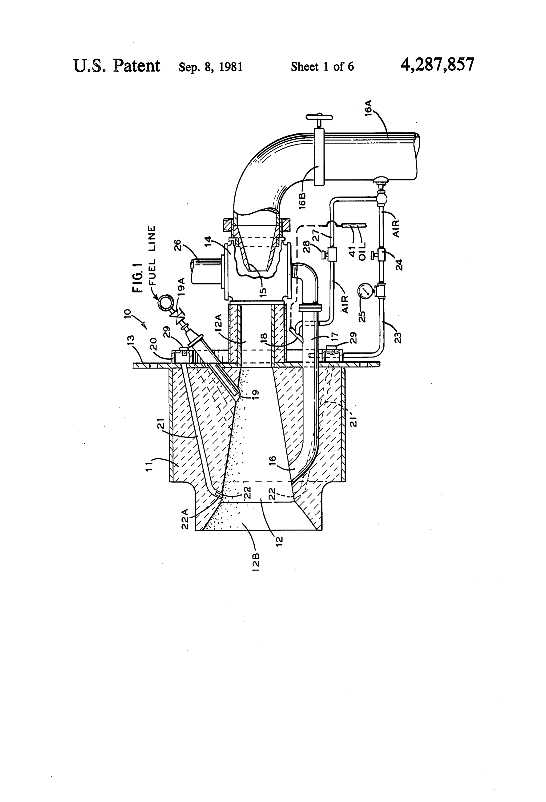
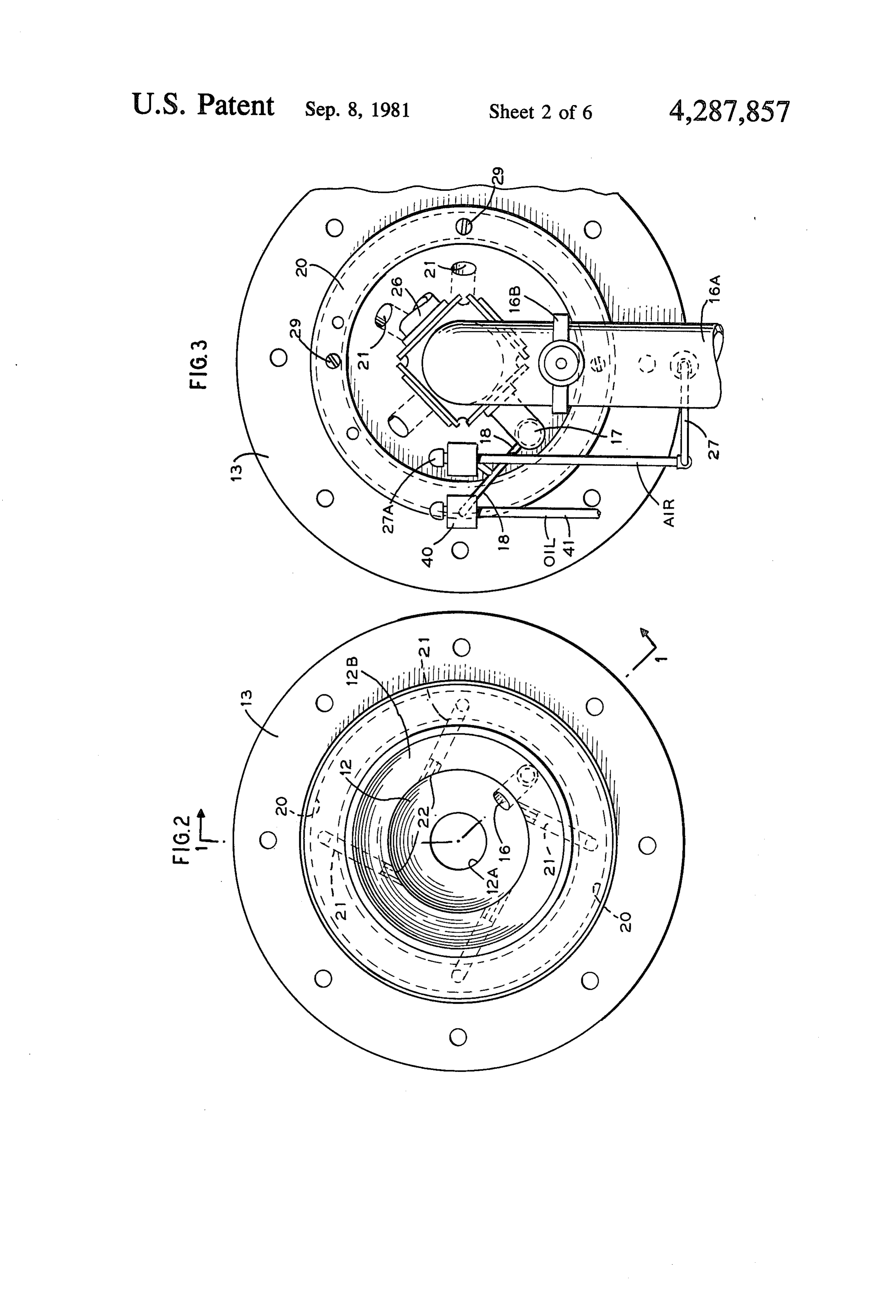
spaced about the outlet of the burner nozzle to intro The introduction of the liquid fuel into the return duce tangential air about the burner flame to control tube 17 during burner operation will result in the hot flame velocity patterns and to effect diffusion burning 35 gaseous products of combustion heating the liquid fuel of the free hydrogen and carbon to thereby generate an so that the fuel is quickly converted into its gaseous intense luminous flame so as to optimize heat transfer by state by the time it enters the mixing chamber where the radiation and conduction. fuel in its gaseous state will mix with the incoming Other features and advantages will become more combustion air to form a generally homogeneous gase apparent when considered in view of the drawings and ous fuel mixture. It will be noted that since the combus specifications in which: tion gases entering the return tube 17 is virtually devoid FIG. 1 is a partial sectional size view of a burner of any oxygen, that no combustion will occur within the construction embodying the invention taken along line return tube, and that the return tube during burner 1-1 on FIG. 2. operation on liquid fuel will function as a gasification FIG. 2 is a front end view of the burner construction 45 chamber in which the fuel is changed from its liquid to of FIG. 1. gaseous state.
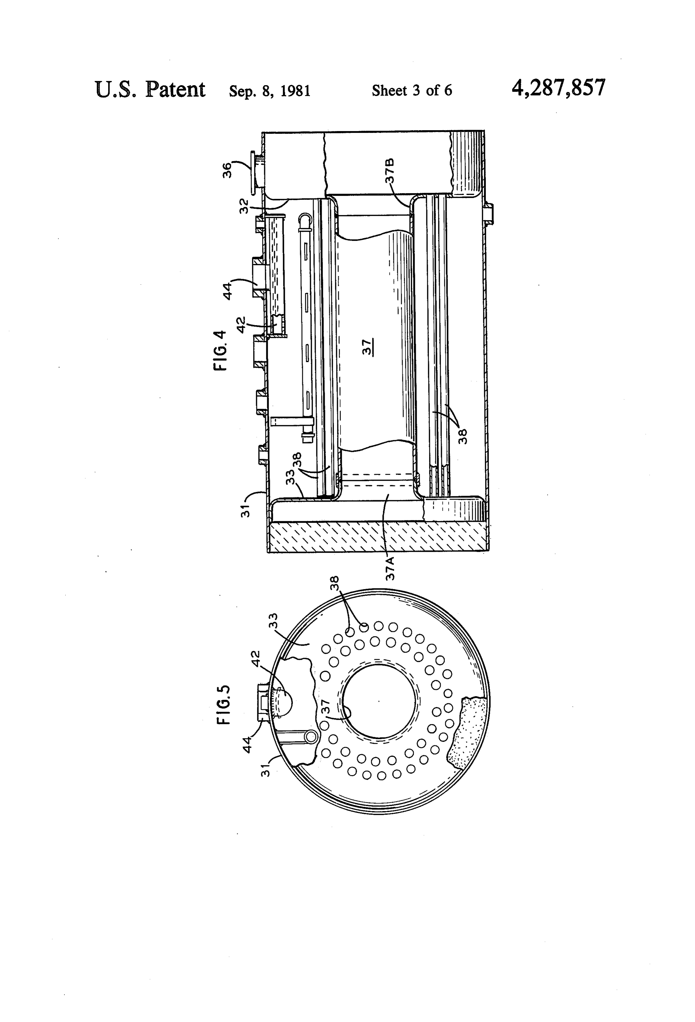
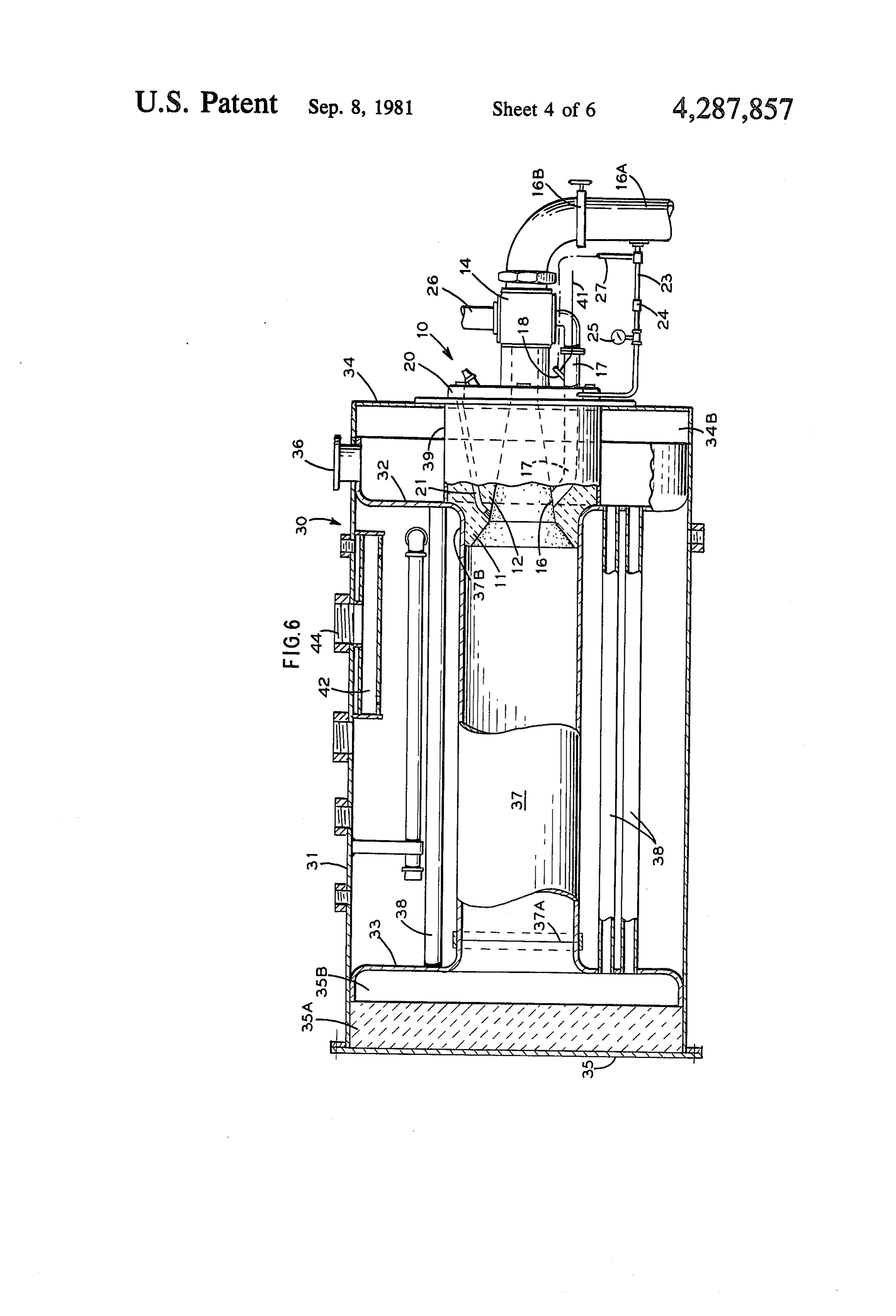
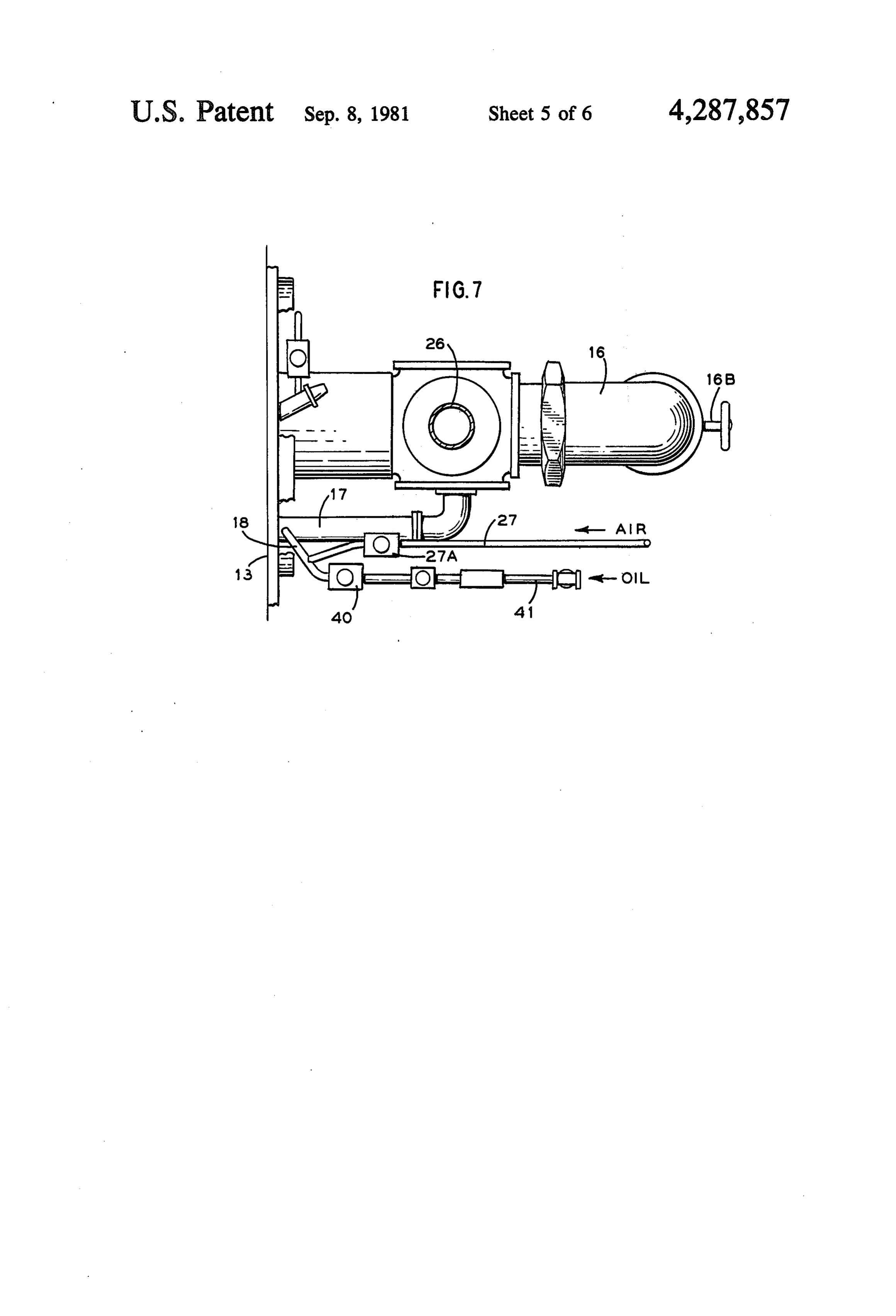
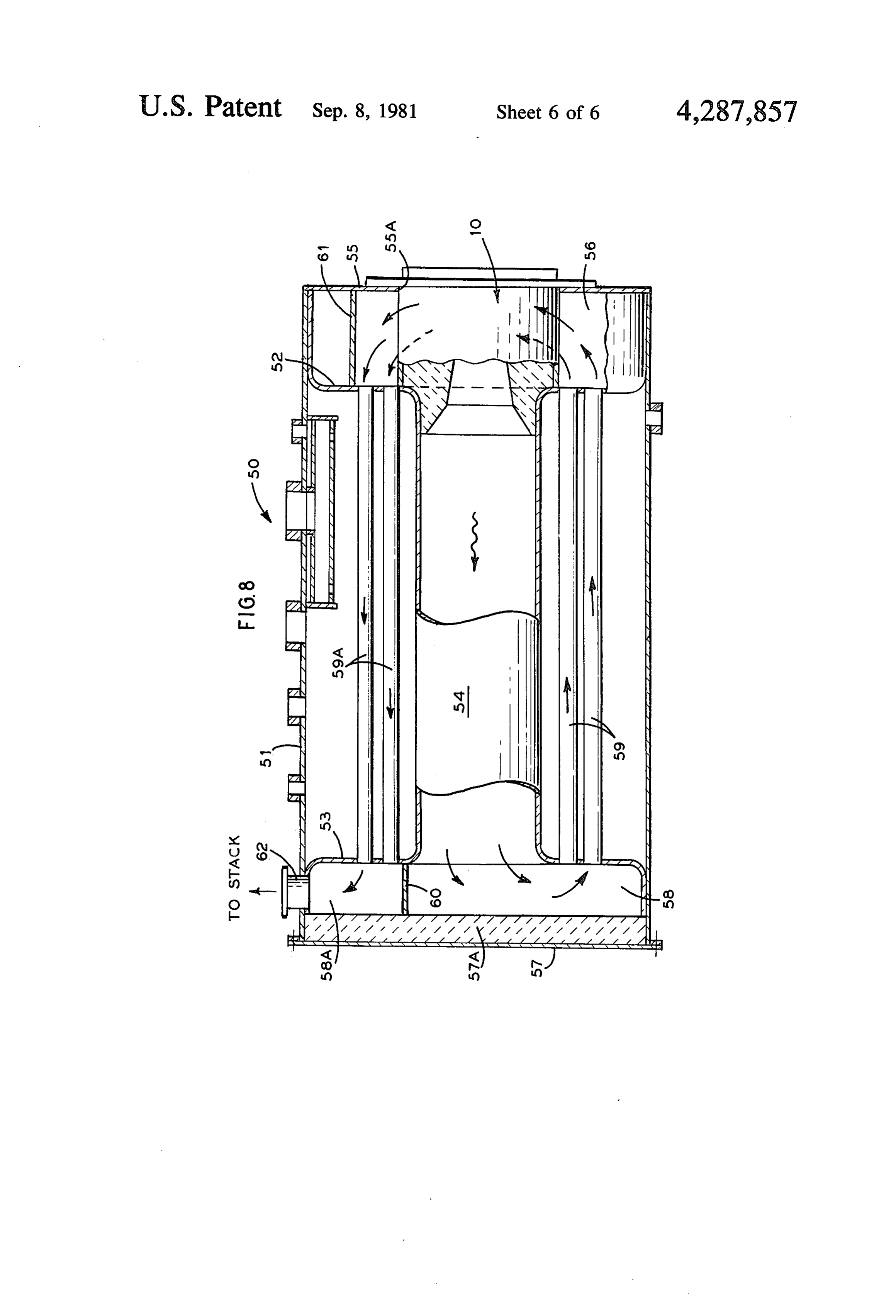
FIG. 3 is a rear end view of the burner construction Means for effecting fuel ignition is achieved by a of FIG. 1. starting or igniting burner 19. It will be understood that FIG. 4 is a section view of a boiler for use with the the igniter burner may be either oil or gas fired. As best burner of FIGS. 1 to 3, with the end wall removed. 50 seen in FIG. 1, the igniter burner is inclined at an angle FIG. 5 is a left end view of FIG. 4; with the end wall to the longitudinal axis of the burner 10, and is directed removed. or aimed at the return gas port 16. The specific location FIG. 6 is a sectional view of the burner-boiler combi of the igniter burner 19 as described achieves two im nation embodying the present invention. portant functions. It is disposed out of alignment with FIG. 7 is a fragmentary top plan view of the burner. 55 respect to the flow of air and fuel mixture so as to not FIG. 8 is a fragmentary section of a modified burner impede the air flow; and the arrangement is such that boiler combination. the initial gasification of the liquid fuel is enhanced as DETAIL SPECIFICATION the procucts of combustion of the igniter burner quickly finds their way to the gas port 16 and return tube 17. It
Referring to the drawings, there is shown in FIGS. 1 has been established that the direction of the igniter to 3 a burner construction 10 embodying the invention. burner 19 toward the gas return port reduces the start It will be understood that the burner 10 has general up time of the burner 10 to less than 30 seconds when utility and can be used in various applications which operating on oil.
call for heating. However, as will be hereinafter de In accordance with this invention, an air manifold scribed, the burner 10 has particular application for 65 chamber 20 is connected to the mounting flange 13. A firing a boiler. plurality of conduits or passageways 21 extending The burner 10 comprises a burner nozzle 11 which in through the burner block 11 connect the manifold the illustrated embodiment is formed of a ceramic block chamber 20 in communication with a series of port 10 openings 22. As shown the port openings 22 are circum scribed. In accordance with this invention, the burner ferentially spaced about the outlet end 12B of the burner block 11 is sized and shaped so as to be disposed in fluid nozzle between the outer end of the nozzle and the gas tight relationship with the front opening 37B of the fire return port 16. It will be understood that a suitable tube 37. The arrangement is such that when the burner interchangeable air nozzle 22A may be disposed in the 10 is firing; the products of combustion are directed port openings 22. The arrangement of the port openings through the fire tube whereby the heat generated by the 22 and nozzle 22A therein is such that air is introduced burner is transmitted to the fire tube by radiation and in a generally tangential manner relative to the burner conduction and then to the surrounding water. The flame generated during combustion. combustion gases eminating from the fire tube 37 to the Air is fed to the manifold 20 from a bleed line 23 10 rear plenum make a second pass through the tubes 38 connected to the main air supply conduit 16A. The and exhaust from the front plenum 34B to the con bleed line 23 may be provided with a suitable control nected stack. It will be understood that the boiler de valve 24 and pressure gauge 25 to control the air flow to scribed includes a feed water means for introducing the manifold 20 and associated ports 22. water into the boiler for maintaining the proper water The burner 10 described can also be fired by a gase 15 lever, and that the boiler includes the necessary dry pipe ous fuel such as a natural or synthetic gas, or low pres means 42 for collecting the steam generated and for sure gas and the like by providing a gas inlet 26 through directing the steam to the steam outlet 44 for distribu which a gas fuel is introduced into the mixing chamber tion to a point of use e.g. a radiator or a processing use. when gas firing is desired. When oil is not being intro Significant of the boiler construction described is that duced into the return tube 17, e.g. when the burner 10 is 20 the boiler 30 when utilized with a burner 10 as described operating only on gas, the return tube 17 is cooled by requires a minimum of heat transfer surface area. For bleeding cooling air thereinto. Such cooling air is sup example, a 40 B.H.P. rated boiler unit fired by conven plied by another air bleed branch 27 coming off the tional or known type of oil burners requires from 200 to main supply. The air bleed branch 27 connects to the oil 400 square feet of heat transfer surface. The boiler 30 as inlet 18 through which cooling air is introduced into the 25 herein described with a like 40 B.H.P. rating and fired return tube when the burner is operating on gas only. A by burner 10, as described requires only 60 to 80 sq. feet valve 28 is provided in bleed line 27 to control the flow of heat transfer surface. This substantial reduction in the of cooling air to the return tube for cooling when gas amount of heat transfer surface required by the inven firing. tion described herein is attributed to the diffusion burn Referring to FIG. 1, the manifold 20 may be provided 30 ing effected by the burner and high surface velocity with spaced openings closed by plugs 29 which are developed by the burner which results in an efficient disposed in alignment with the passageway or conduits transfer of heat to the heating surface of the boiler by 21 which connect the manifold 20 to a port 22. The both radiation and conduction.
openings closed by plugs 29 provide a means whereby FIG. 7 illustrates a modified boiler construction. one or more passageways 21 can be rendered inopera 35 FIG. 7 discloses a boiler construction 50 similar to that tive. This can be attained by suitably closing one or of FIG. 4, 5, and 6, except the modified construction of more of the passageways 21, if desired, by means of the FIG. 7 is a three pass boiler whereas the construction of access provided by the opening closed by plug 29 oppo FIGS. 4 to 6 is a two pass boiler.
site a given passageway 21. As shown in FIG. 7 the boiler 50 comprises an outer The burner 10 described in addition to having general boiler shell 51 closed by opposed end header walls 52 utility is particularly suitable for firing a boiler. Refer and 53. Interconnected between header walls 52 and 53 ring to FIG. 6, the burner 10 is illustrated in combina is the main fire tube 54. Spaced from header wall 51 in tion with a boiler 30 which is particularly compatible the front wall 55 which is provided with a burner open with the burner to define a package unit which is capa ing 55A for receiving a burner 10 as hereinbefore de ble of generating steam in approximately 5 minutes from 45 scribed. The space between the front wall 55 and the a cold start; and which is capable of attaining a mini front header wall 52 defines a plenum chamber 56. A mum of 86% thermal efficiency and results in a fuel rear wall 57 lined with refractory 57A is spaced from savings of 20 to 40% over that of a comparable size the rear header wall 53 to define a rear plenum chamber boiler fired with conventional or known type oil burn 58. Interconnected between header walls 52 and 51 are es. 50 a plurality of tubes 59.
The boiler 30 includes an outer cylindrical shell 31 Extending transversely of the rear plenum chamber which is interconnected between a pair of header. end 58 is a baffle 60 which partitions the chamber so as to walls 32 and 33. End wall 35, lined with suitable refrac direct the gases exiting from the fire tube 54 below the tory material 35A, is spaced from header wall 33 to baffle 60 to be directed through the lower tube 59 to define a plenum chamber 35B. The front end wall 34 is 55 define a second gas pass.
spaced from the header wall 32 to define a plenum A baffle 61 extends transversely of the front chamber chamber 34B, and need not require an insulating liner. 56 for directing the gases exiting from the second pass Chamber or plenum 34B includes a vent 36 which con tubes 59 to the upper tubes 59A to define a third gas nects to a suitable stack (not shown) which exhausts to pass. The gases exiting from the third pass exhaust to the atmosphere. the chamber 58A defined above baffle 60 and which Interconnected between the opposed header walls 32 chamber 58A exhausts to vent or stack 62. In all other and 33 is a fire tube 37, the rear end 37A of which is respects, the boiler 50 is similar to that herein before disposed in communication with plenum 35B. Circum described.
ferentially spaced about the fire tube 37 are a plurality The operation of the burner and boiler is as follows: of tubes 38 which are also interconnected between the 65 When operating on oil, at cold start the valve 19A header walls 32 and 33. In the illustrated embodiment controlling the flow of fuel to the igniter burner 19 is the front wall 34 is provided with a burner opening 39 opened and burner 19 is ignited. It will be understood which is sized for receiving the burner 10 herein de that the igniter burner 19 may be either oil or gas fired.
Page 11scan →
The arrangement and location of the igniter burner 19 is maintaining the high surface velocity for optimum heat such that its hot products of combustion are directed transfer.
toward the gas return port 16 so that the return tube is The burner 10 described can also be fired solely by immediately functioning for returning hot products of gas and/or in combination with liquid fuel. When gas combustion to the mixing chamber. With the hot prod firing only is desired, the valve 40 to the oil line 41 is ucts of combustion generated by this igniter burner turned off and the gas valve in the gas line 26 is opened. flowing through the return tube 17, the valve 40 con The gas fuel is directly introduced into the mixing trolling the "run' oil is opened and the oil is introduced chamber 14 through conduit 26 where it is mixed with through inlet 18 into the return tube 17 where it is gas air to form the gas-air combustible mixture and is ig ified by the heat of the combustion gases flowing there 10 nited similar to that hereinbefore described. However, through. The gasified liquid fuel is then induced into the when gas only is being used as the main fuel, provision mixing chamber 14 where it is mixed with the combus must be made to cool the return tube 17 to prevent burn tion air which is being injected through nozzle 15 under out. This is attained by bleeding some cold air from the pressure and controlled by valve 16A to form a gener main air supply 16A into the return tube 17 through ally homogeneous fuel gas and air combustible mixture. 15 bleed line 27 to cool the return tube 17. The bleed line Due to the change of state of the fuel oil from a liquid 27 connects to the oil inlet 18 whereby air is introduced to a gas prior to combustion, the amount of air injected into the return tube, when oil is not being used to cool through the air nozzle is controlled so that only the the return tube 17. A suitable solenoid valve 27A is optimum amount of air needed for combustion is per disposed in bleed line 27 to control the flow of cooling mitted to the mixing chamber. The gas-fuel mixture 20 air to tube 17. It will be understood that air from the discharging through the burner nozzle is then ignited by manifold is directed to the tangential ports 22 when gas the ignition burner 19. Once the main flame has been is being fired through the burner 10 in a manner similar established, the burner 19 is turned off and the flame is to that described with respect to the burner operating rendered self perpetuating until the supply of fuel to with liquid fuel.
inlet 18 is interrupted. The flame thus produced is a blue 25 From the foregoing description, it will be noted that flame having a heat intensity sufficient to cause a break the boiler can be fired by either a liquid fuel or gaseous down of the hydrocarbons into its base elements e.g. fuel and/or simultaneously on both merely by the suit hydrogen and carbon. able control of the valves controlling the flow of the In accordance with this invention a portion of the air respective fuels to the burner. It will also be understood from the main supply 16A is bled through line 23 to the 30 that suitable automatic control means can readily be manifold chamber 20 from whence the slight amount of adapted to the burner and/or boiler to effect fully auto air i.e. less than 3% is distributed to a plurality of ports matic control thereof.
22 spaced out the discharge end of the nozzle 12B. The While the invention has been described with respect air introduced through ports 22 imparts an action to the to several embodiments thereof, it will be appreciated flame which functions to shorten, but maintain surface 35 and understood that variation and modification may be velocity thereof, and at the same time supplies the oxy made without departing from the spirit or scope of the gen needed to effect the diffusion burning of the free invention.
hydrogen and carbon present. This diffusion burning I claim: - thus provides the blue flame generated by the burner 1. A burner for burning a gasifiable liquid fuel com with a ring of hot illuminous gas which enhances the prising heat transfer of the hot products of combustion to the a burner nozzle having an inlet and an outlet, heat transfer surfaces of the boiler. The diffusion burn a mixing chamber connected in communication with ing effected hereby permits heat to be transferred said inlet;
quickly and rapidly by both radiation and conduction. means for introducing combustion air into said mix It has been discovered that due to the combustion capa 45 ing chamber under pressure whereby the velocity ble of the described burner, that in a 40 B.H.P. rated of the combustion air through said mixing chamber boiler, steam can be generated from a cold start in ap creates a zone of reduced pressure in said mixing proximately 5 minutes. As a result, the cycle time that chamber, the burner is required to operate to maintain the boiler said nozzle having a gas return port adjacent to the at operating conditions is therefore materially reduced 50 outlet of said nozzle, and to result in substantial fuel savings. Fuel economy is a return tube interconnected between said gas return further enhanced in that the combustion efficiency of port and said mixing chamber whereby the Zone of the burner is vastly improved as the liquid fuel is being reduced pressure in said mixing chamber induces a burned as a gas rather than a liquid which results in flow of hot combustion gas through said gas return virtually all of the fuel being consumed. Because of the 55 port and connected return tube to said mixing total combustion afforded by the described burner, the chamber, pollutents resulting from the products of combustion are means for introducing a liquid fuel into said return reduced to a minimum. Also the burning of liquid oil in tube whereby the hot gases of combustion effect its gaseous state reduces the formation of soot and car the gasification of the liquid fuel prior to said fuel bon which would otherwise form on the heat transfer entering into said mixing chamber to mix with said surface of the boiler. Thus the described boiler will air to form a combustible gaseous mixture; require little if any cleaning and the thermal efficiency ignition means disposed relative to said nozzle to thereof can be maintained throughout its period of oper effect ignition of said combustible gaseous mixture, ation with a minimum of maintenance or cleaning. whereby a flame having a high flame velocity and By proportioning the amount of combustion air and 65 very high flame temperature is achieved so as to diffusion air by control of valves 16B and 24, the inten cause a break down in a portion of the hydrocar sity of the burner flame and/or luminousity of disfusion bons into their basic elements hydrogen and car burning can be controlled over a wide range while bon, and a means disposed adjacent to the outlet of 12 said burner nozzle for directing an air stream in a 13. A boiler capable of generating steam or hot water generally tangential direction relative to the longi in a matter of a few minutes from a cold start compris tudinal axis of said nozzle and burner flame therein ing a boiler shell having a pair of spaced apart end whereby said air stream effects the diffusion burn header walls and an end wall spaced from the respective ing of the free hydrogen and carbon and the main header walls so as to define a plenum between each of taining of said velocity. said header wall and adjacent end wall, 2. A burner as defined in claim 1 wherein said last a fire tube interconnected between said header walls, mentioned means are disposed between said burner and a burner means firing into said fire tube, outlet and said gas return port. said burner means including a burner nozzle disposed 3. A burner as defined in claim 1 wherein said last 10 in fluid tight sealing relationship with said fire tube, mentioned means includes a plurality of ports circum said nozzle having an inlet and an outlet, ferentially spaced about the outlet of said nozzle a mixing chamber in communication with said inlet, whereby said spaced ports are disposed generally tan means for introducing combustion air into said gential of said outlet; and an air manifold disposed about mixing chamber under pressure whereby the veloc said nozzle, and a passageway interconnecting said 15 ity of the air creates a zone of reduced pressure in manifold to each of said spaced ports; and means for said mixing chamber, supplying said manifold with air. said nozzle having a gas return port, a return tube 4. A burner as defined in claim 3 and including means interconnecting said return port to said mixing for controlling the flow of air through one or more of chamber, whereby the zone of reduced pressure in said passageways. said mixing chamber induces a flow of hot combus 5. In a burner for burning a gasifiable liquid fuel hav tion gases through said gas return port and con ing a burner nozzle provided with an inlet and an outlet, nected return tube to said mixing chamber, a mixing chamber connected in communication with means for introducing a liquid fuel into said return said inlet; means for introducing combustion air into 25 tube whereby the hot gases of combustion effect said mixing chamber under pressure whereby the veloc the gasification of said liquid fuel prior to mixing ity of the combustion air through said chamber creates with the combustion air in the mixing chamber to a zone of reduced pressure in said mixing chamber, a gas form a combustible gaseous fuel-air mixture return port adjacent to the outlet of said nozzle, and a means disposed about the outlet of said burner nozzle gas return tube connecting said return port to said mix 30 for directing a stream of air about said outlet in a ing chamber, and means for introducing a liquid fuel generally tangential direction relative to the axis of into said return tube whereby the hot gases of combus the burner nozzle whereby said stream of air effects tion effects a gasification of the liquid fuel prior to en the diffusion burning of the free hydrogen and tering said mixing chamber to form a combustible gase carbon in the flame to generate an illuminous flame ous fuel mixture, the improvement of an igniting means 35 to transmit heat by both radiation and conduction to the fire tube so as to maximize heat transfer to for igniting said gaseous fuel mixture, said igniting the boiler water, and means being disposed at an angle relative to the axis of an ignition means for igniting the gaseous fuel-air said nozzle, and said igniting means being generally mixture.
directed toward the gas return port. 14. A boiler as defined in claim 13 wherein said igni 6. The burner as defined in claim 5 wherein said ignit tion means comprises a burner igniter disposed at an ing means comprises a fuel burner; said fuel burner angle to the axis of the burner nozzle, said burner igniter being angled toward said gas return port so that the being directed toward said gas return port to quickly products of combustion of said fuel burner are utilized to rapidly initiate the gasification of the liquid fuel intro initiate said gas the flow of hot products of combustion through return port.
duced in said return tube. 45 15. A boiler as defined in claim 13 and including a 7. The burner as defined in claim 6 wherein said fuel plurality of tubes interconnected between said header burner comprises a gas burner. wall and circumferentially spaced about said fire tube, 8. The burner as defined in claim 6 wherein the fuel said tubes defining a second gas pass whereby the gases burner comprises a liquid fuel burner. passing therethrough are discharged into an adjacent 9. The burner as defined in claim 5 including a plural 50 plenum for exhausting to atmosphere. ity of port circumferentially spaced about said outlet, an 16. A boiler as defined in claim 15 and including a air manifold, a passageways interconnected between second series of tubes spaced about said fire tubes, said each of said plurality of ports and said air manifold; said second series of tubes defining a third gas pass whereby plurality of ports being disposed between said outlet the gases passing through said second series of tubes are and said gas return port, and means for introducing air 55 exhausted to atmosphere.
into said manifold and connected plurality of ports 17. A compact burner-boiler combination having an whereby air discharging through said plurality of ports improved heating cycle for effecting substantial fuel effects the diffusion burning of the free hydrogen and savings and capable of being fired alternately and/or carbon in the flame. simultaneously with a gaseous and/or liquid fuel com 10. The burner as defined in claim 6 wherein said 60 prising a boiler shell, a pair of spaced apart header walls burner is disposed downstreamwise of said mixing connected to said boiler shell, and an end wall spaced chamber so as to provide an unimpeded air flow from each of said header walls to define a plenum be through said mixing chamber. tween each said end wall and its adjacent header wall, 11. The burner as defined in claim 9 and including a fire tube interconnected between said header walls, interchangeable nozzles for controlling the flow of air 65 a plurality of tubes interconnected between said through said plurality of ports. header walls, 12. A burner as defined in claim 5 in combination one of said end walls having a burner opening; a with a boiler. combination gas and oil burner mounted in said 13 burner opening, said burner having a nozzle dis sion of heat energy to said fire tube both by radia posed in fluid-tight sealing relationship with said tion and conduction.
fire tube, and said nozzle having an inlet end and an 18. A compact burner-boiler combination as defined in claim 17 wherein said last mentioned means con outlet end, prises a plurality of ports circumferentially spaced said outlet end being disposed in said fire tube, a fuel about the outlet of said burner nozzle, an air manifold, air mixing chamber disposed in communication and a plurality of passageways interconnecting said with said nozzle inlet, means for introducing air plurality of ports to said manifold, said ports being ar under pressure into said mixing chamber; a gas ranged to introduce air in a generally tangential direc return port disposed adjacent to the nozzle outlet, O tion relative to the axis of said burner nozzle whereby a return tube interconnecting said gas return port to said air effects the diffusion burning of the free hydro said mixing chamber, means for introducing a liq gen and carbon in the flame and functions to shorten the flame pattern and maintain surface velocity to effect a uid fuel into said return tube whereby the hot gases maximum transfer of heat energy by both radiation and of combustion effect a gasification of the liquid fuel conduction.
prior to entering into said mixing chamber; means 19. A burner-boiler combination as defined in claim for introducing an alternate gaseous fuel into said 18 and including means for introducing cooling air into mixing chamber; an igniting burner nozzle said return tube when said burner is being fired by a gas whereby said igniting burner is directed toward only being introduced into said mixing chamber said gas return port whereby the products of com through said alternate fuel means. 20. A burner-boiler combination as defined in claim bustion of said igniting burner effect the initial 16 and including a second series of tubes interconnected gasification of said liquid fuel, and between said header walls; said second series of tubes a means for effecting a burner flame velocity and defines a third set of heat transfer surfaces. diffusion flame pattern for enhancing the transmis 25 X
Provenance
- Collection
- Patents citing this work
- Pages
- 13
- Method
- pdftotext (the PDF's own text layer) + pdftoppm 300dpi page scans
- Patent office record
- patents.google.com →
- Source
- Google Patents citing-documents table
- Assignee
- Leo Schnitzer
- Published
- 1981-09-08
- Transcribed from
- patentimages.storage.googleapis.com →