

patent · US4289112A
Heat storing solar collector device
15 September 1981
Text
Page 1bibliographic recordscan →
Roseen
(54) HEAT STORING SOLAR COLLECTOR
DEVICE
Inventor: Rutger A. Roseen, Nyköping,
Sweden Assignee: Studsvik Energiteknik AB,
Nyköping, Sweden
30 Foreign Application Priority Data
Nov. 1, 1977 SEl Sweden ................................ 7712327 Int. Cl. ................ ................................ F24J3/02 52 U.S. Cl. ................................... 126/415; 126/438:
1969,839 8/1934 Goddard ............................. 126/440 3,915, 148 10/1975 Fletcher......... 126/440 3,982,527 9/1976 Cheng et al. ... ... 126/438 3,988, 166 10/1976 Beam .............. ... 126/439 4,134,393 1/1979 Stark et al. . ... 126/440 4,146,015 3/1979 Acker ..... ... 126/415 4,148,301 4/1979 Cluff....... ... 126/438 4,188,941 2/1980 Hopkins .............................. 126/440
FOREIGN PATENT DOCUMENTS
148278 9/1952 Australia ............................. 126/438 994.106 1/1951 France ..... ... 126/415
Primary Examiner-James C. Yeung
Attorney, Agent, or Firm-Christie, Parker & Hale
A solar collector device is placed on a floating insulat ing lid of arreservoir containing a heat storing liquid. The solar collector device comprises lens means which concentrate incident solar radiation to focal points or focal lines rear or at the lid, and the lid has apertures through which the focus portions of the radiation beams pass with snug clearance. Transparent evaporation pre venting diaphragms seal the appertures. Electricity generating semi-transparent solar cells may be arranged in the apertures, whereby incident solar radiation partly produces electricity, partly heats the liquid, and whereby the liquid cools the cells. In the case the lens means comprise axially elongated lenses in parallel with the lid and the apertures are slots, aligned with the lens axes, the lid is rotatable whereby to maintain the lens axes, the slots and the sun radiation in one and the same plane during day time.
19 Claims, 8 Drawing Figures
Drawings
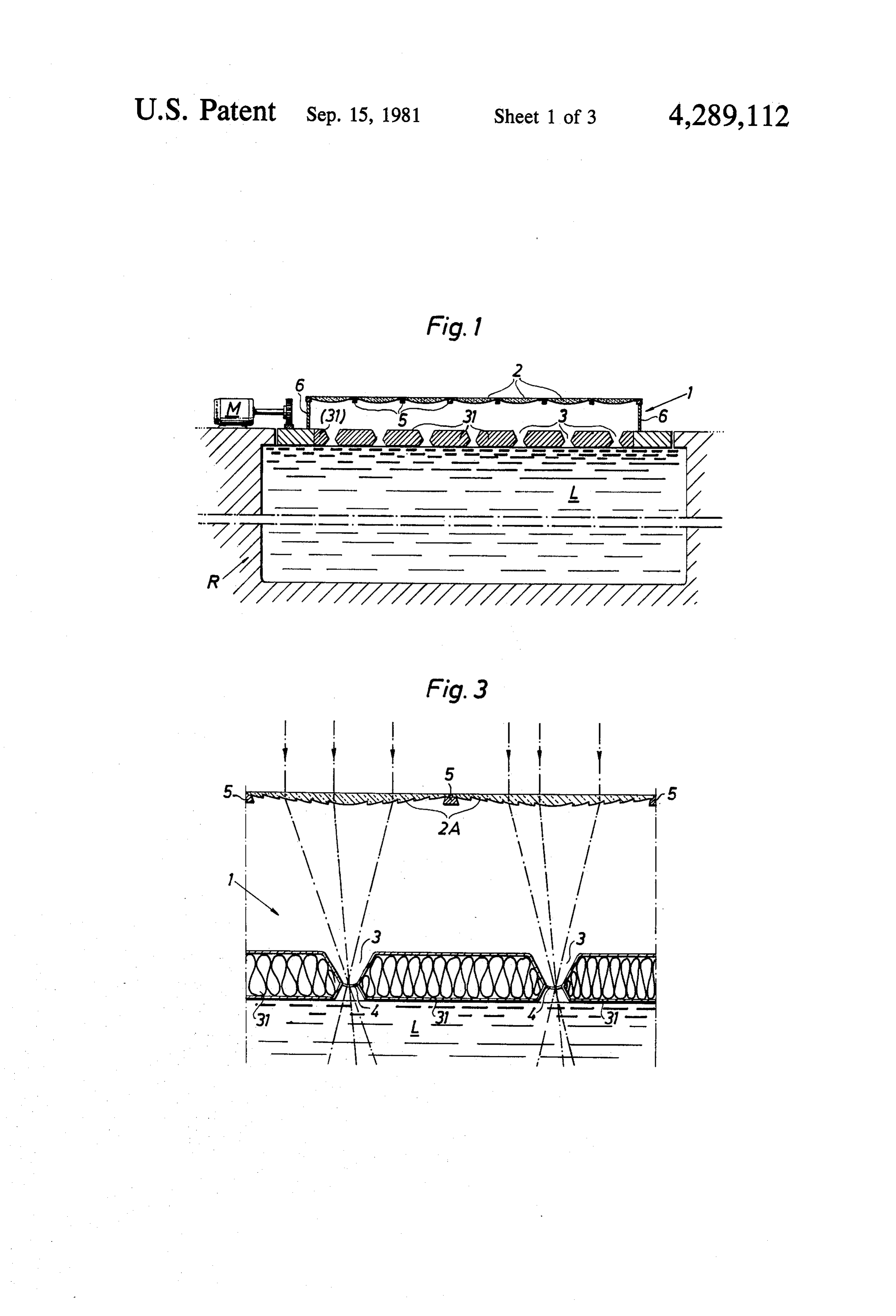
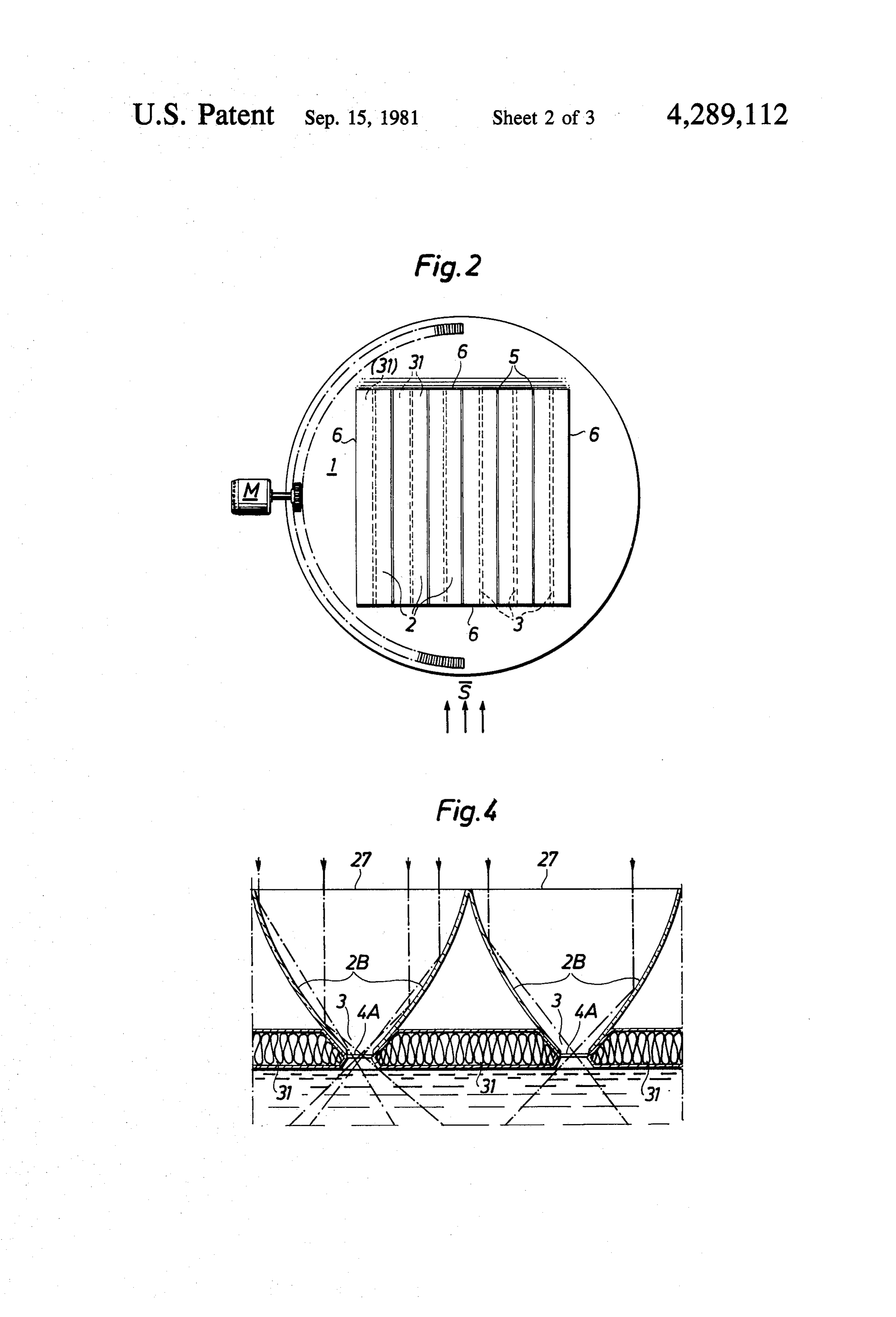
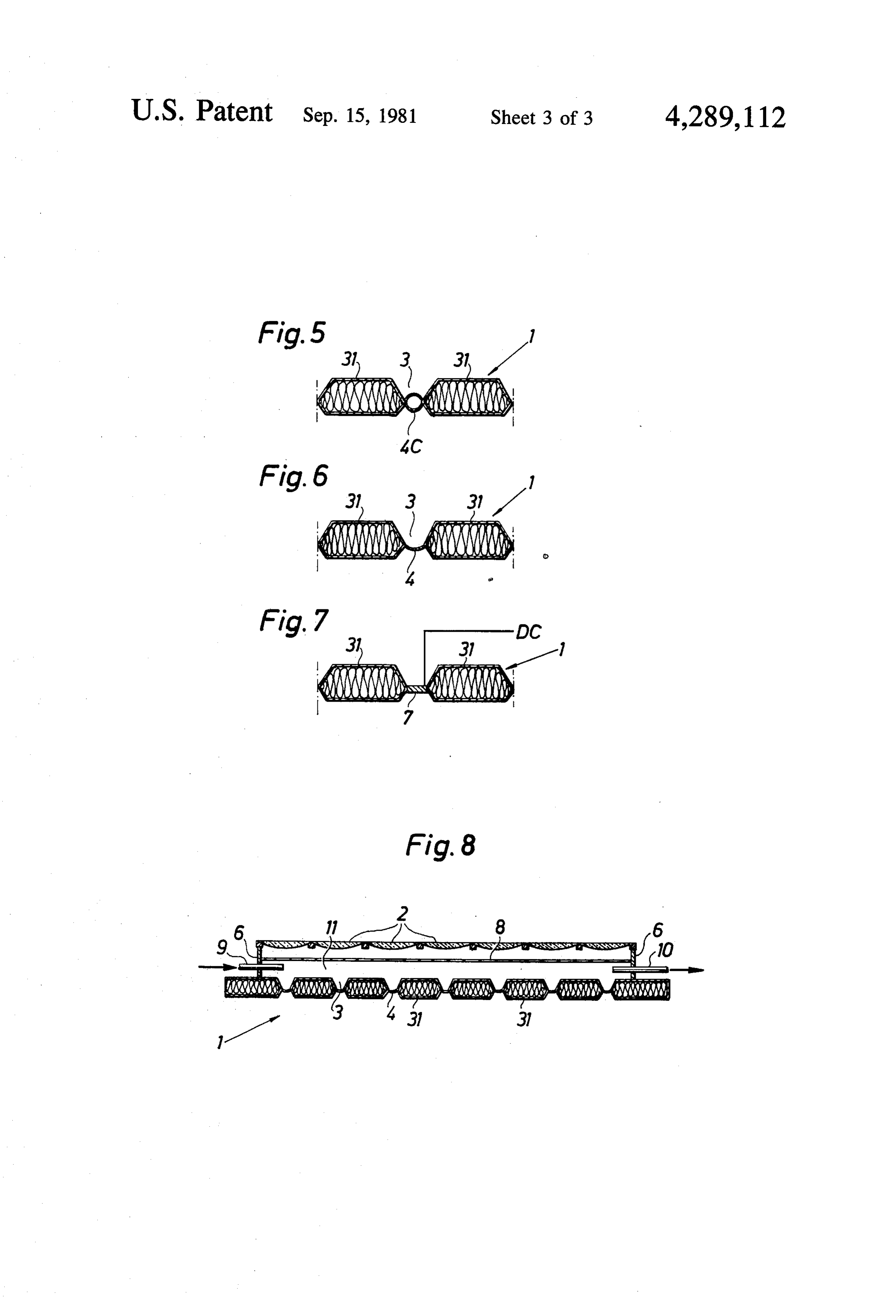
FIG. 8 is a schematic front elevation sectional view and to arrange them close to each other as is shown in of means for introduction and removal of an insulation FIG. 4.
FIG. 1 shows a liquid reservoir R which contains preferably is evacuated. The tube 4c offers, due to the liquid L on the surface of which a lid 1 floats. The lid 1 curvature of the tube wall, minimum reflection losses, which comprises an insulating material, is arranged and offers also a high transmission due to the evacua rotatable by means of a drive motor M. The lid has a tion.
Page 2drawing sheetscan →
Page 3drawing sheetscan →
Page 4drawing sheetscan →
Page 5scan →
lid, whereby the lenses may be utilized as a convection
HEAT STORING SOLAR COLLECTOR DEVICE protection.
BACKGROUND OF THE INVENTION 5 ofAlternatively, the solar collector means may consist mirroring surfaces having a shape substantially corre
The present invention refers to a heat storing solar sponding to axial symmetric parabolic reflectors each collector device comprising a liquid reservoir with an having a central aperture at a slot in the lid, the "focal insulating lid floating on the liquid surface, solar collec point" of each reflector suitably being located at the tor means being arranged above the lid for heating of narrowest portion of the slot. The solar collector the liquid in the reservoir. means, whatever way they are designed, are perferably Solar collector devices of the type indicated above dent solaradjacent 10 arranged each other in order to receive inci radiation energy over substantially the entire are previously known, at which the solar collector surface area of the lid over which the solar collector means consist of lenses or reflectors which concentrate the incident solar energy onto heat absorption tubes tively means are arranged. The slots and the apertures respec through which a liquid flows. At such known devices may be entirely free such that the liquid is ex circulation systems for transport of the liquid through 15 posed in the slots, but preferably the slots are at their the absorption tubes are required and moreover, it is lower portions screened off by means of one or more normally required that the heat absorption tubes are radiation energy permeable sealing diaphragms. A tube may be arranged in each slot to the formation of two designed in specific ways in order to take care of the diaphragms incident solar energy to the maximum extent. Despite 20 ated. therein, said tube preferably being evacu advanced designs of the absorption tubes the devices exhibit relatively low efficiency, partly because the lens areThe lid may comprise parallel blocks or rods which means and the reflectors respectively cannot even ap distances in themaintainable arranged at predetermined mutual horizontal direction in order to form proximately be made optically perfect, which brings said slots. The rods may then also be adapted to be about that portions of the concentrated radiation energy 25 gathered and possibly also completed with one or more beams fall outside the absorption tubes, partly due to the further rods, whereby the insulation capability of the lid shallow energy absorption depth of the absorption may be enhanced tubes; a relatively large energy absorption depth would nation of the slots.during night time for example, elimi be desirable in the light of the wide frequency spectrum Further the space between the lid and the lenses may of the incident solar energy. 30 be screened off, and means may be arranged for intro An object of the present invention is therefore to duction and removal of an insulation material in the devise a solar collector device of the preamblewise shape mentioned type, at which said draw-backs are avoided. In the ofcasea powder or foam, for example, in said space. of lenses it is also possible to arrange a sepa
Other objects and advantages with the invention will rate transparent convection guard in the area between appear in the following. 35 the lenses and the lid, and means may be arranged for SUMMARY OF THE INVENTION introduction and removal of insulation material in the According to the invention there is provided a heat liquid space between the convection guard and the lid and the . . storing solar collector device of the preamblewise men virtue surface of the or diaphragms arranged in the slots. By advantageous design of the inventive de tioned type, which substantially is characterized in that vice it is favorable to arrange apertures are arranged in the lid and in that the solar energy cells, so called solar cells, inelectricity connection generating with the collector means are arranged to gather radiation energy apertures in the lid, said energy cells being arranged to incident against the device to concentrated radiation transmit unused radiation energy to the liquid mass. energy beams, which fall through the apertures such Further the liquid of the reservoir may consist of water that the radiation energy is absorbed directly in the 45 having such a salt concentration, that the hottest liquid liquid mass of the reservoir. is gathered in the bottom layer of the reservoir. The lid The surface area of the apertures merely constitute a and the solar collector means are suitably arranged fraction of the surface area of the lens means.
In a preferred embodiment of the invention, the aper rotatable can be such that the solar collector means thereby maintained aligned with the sun and such that the tures consist of narrow elongated parallel slots in the 50 concentrated energy lid, the solar collector means being arranged to gather are maintained alignedbeams leaving the solar collectors with the apertures in the lid.
incident radiation energy to narrow elongated radiation The invention is defined in the appended claims. energy beams which fall through the slots.
The width of the slots and the dimensions of the BRIEF DESCRIPTION OF THE DRAWINGS apertures respectively, are adapted to the refraction 55 FIG. 1 is a schematic front elevation cross sectional capability and focal distance of the lens means such that view of a heat storing solar collector device according the slots and the apertures respectively just can let to the invention;
through the entire radiation energy beams, Preferably FIG. 2 is a top plan view of the device of FIG. 1; the lens means are arranged in such a way that their FIG. 3-is an exploded view of two lenses and aper focal points or the similar lie at the smallest dimension 60 tures of the device of FIG. 1;
of the slot and the apertures respectively. FIG. 4 is a front elevation view of an alternative The solar collector means may consist of axial sym embodiment of a solar collector means of FIG. 1; metric lenses which are arranged above and in parallel FIG. 5 is an exploded view of an alternate embodi with the lid, and the lenses may then be, designed as ment of the aperture of FIG. 3;
Fresnel-lenses, preferably of a plastic material such as 65 FIG. 6 is an exploded view of an alternate embodi poly(methyl methacrylate). The lenses may then be ment of the aperture of FIG. 3; located closely adjacent each other so that they to FIG. 7 is a front elevation view of a solar cell ar gether form a transparent covering surface above the ranged in an aperture in the lid of FIG. 1; and
Page 6scan →
FIG. 8 is a schematic front elevation sectional view and to arrange them close to each other as is shown in of means for introduction and removal of an insulation FIG. 4.
material in the space above the lid. FIG. 5 shows schematically a portion of the lid 1, a
Detailed description
diaphragm 4c being arranged in the apperture 3. The diaphragm 4c is formed of a transparent tube which
FIG. 1 shows a liquid reservoir R which contains preferably is evacuated. The tube 4c offers, due to the liquid L on the surface of which a lid 1 floats. The lid 1 curvature of the tube wall, minimum reflection losses, which comprises an insulating material, is arranged and offers also a high transmission due to the evacua rotatable by means of a drive motor M. The lid has a tion.
plurality of apertures 3. A lens 2 is arranged above each 10 FIG. 6 shows an alternative diaphragm 4 for the aperture 3, said lens being arranged to gather incident apperture 3. In FIG. 6 the diaphragm is precurved and solar radiation to a narrow energy beam which falls made of a resilient material such that the insulation of through respective aperture 3 in the lid 1. The lenses 2 the lid may be enhanced during night time for example, are supported from the lid by means of a support means 15 by bringing the rods or blocks 31 defining the apertures 5 and are arranged adjacent each other, such that they 3 closer to each other. Then the diaphragm 4 will be together form a convection barrier. The space between bent in a predetermined way such that the blocks 31 can the lenses 2 and the lid 1 is screened off by means of side be brought into engagement with each other. panels 6. Due to the principle operation of the inventive de FIG. 2 shows a horizontal view of the device accord 20 vice, the device is especially well suited to be combined ing to FIG. 1, and is intended to illustrate that the motor with so called solar cells. Such solar cells may be posi M is arranged to rotate the lid 1 such that the longitudi tioned in or at the apertures 3 and may then be arranged nal axes of the lenses 2 are maintained in parallel with above, below or between diaphragms in the appertures vertical planes through the direction of the incident 3 and be arranged to transmit to the liquid mass L the solar radiationS. FIG. 2 illustrates also that the lenses 2 25 radiation energy, which is not taken care of by the solar are axial symmetric and elongated and that the slots 3 in cell for electricity generation DC. Furthermore, it is the lid 1 are narrow centered elongated and centred apperciated that the solar cells 7 to the extent they are against the lenses 2. transparent, can serve as diaphragms themselves. FIG. 3 illustrates a detail of a device according to FIG. 8 shows a device of the design principle re FIG. 1, wherein the lenses 2a are shown designed as 30 vealed in FIGS. 1 and 2, wherein an inlet means 9 and Fresnel-lenses, preferably of plastic. Such lenses may an outlet means 10 are arranged to introduce and re simply be manufactured for example by an extrusion move respectively an insulation material such as a pull process or by axial profile machining of a plate shaped Verous insulation material or a foam material into and material. Moreover, it is appreciated that axial symmet from respectively the space present between the lenses ric lenses of the type illustrated in FIGS. 1 and 2 also 35 2, the lid 1 (and the liquid surface and the diaphragms in may be located closely adjacent each other such that the apertures 3 of the lid respectively) and the panels 6. they also serve as a convection barrier. The apertures 3 As indicated in FIG. 8 a separate convection guard 8 in the lid may be chamferred in the illustrated way in may be arranged in said space in order to better define order to permit the gathered radiation beams to snugly the volume of the insulation material 11 and further but freely pass the aperture, and moreover one or more more, offer an enhanced convection protection when diaphragms 4 are preferably arranged in each aperture 3 the device is in operation. The means 9 and 10 may in order to prevent evaporation of liquid therethrough. consist of feed tubes which are connected to fans or The lenses 2 are designed and located such that their pumps. .. .
focal points lie in the area of the narrowest portion of In the drawings the lenses 2, 2a and the reflector pairs the aperture 3, but it should be clear that it is also possi 45 2b have been illustrated as having an axial symmetric ble to design the apparatus in such a way that the focal design and the apertures 3 have been shown as elon point will lie a small distance below the diaphragm 4 or gated slots which are centered or aligned therewith, but a small distance above the diaphragm 4. it should be appreciated that it is conceivable to rather FIG. 4 shows an alternative to the arrangement ac let the device comprise rotational symmetric lenses or cording to FIG. 3, wherein the solar energy collecting 50 the like, in which case the apertures should have a shape means consist of reflector pairs 2b which deflect the of Substantially round holes. In the last mentioned case incident solar radiation to a "focal point", which lies in it should also be appreciated that the lid not necessarily or near the narrowest portion of the aperture 3. Also in has to follow the wandering of the sun and therefore be this case a diaphragm pair 4 may be arranged in the rotatable; rather the aperture could be designed with an narrowest portion of the slot in order to avoid an evapo 55 elongated arched shape corresponding to the wander ration of liquid therethrough. However, it should be ing of the focal point during the day. appreciated that in this embodiment it could be useful In the illustrated embodiment the focal point has been not to have any diaphragms 4,4a in the apperture 3 as shown to lie in the narrowest portion of the aperture 3, thereby precipitation may be drained directly down but it is appreciated that it may be desirable to locate the into the liquid mass L of the reservoir R. Also in this 60 focal point at a small depth in the liquid mass, for exam case it is possible to locate adjacent reflector pairs 2b ple at the level of the bottom surface of the lid 1, partly close to each other such that a maximum portion of in order to reduce heating of the diaphragms 4 as far as incident solar radiation can be taken care of. However, possible and, partly in order to achieve a maximum it is preferred to arrange at least one diaphragm at the temperature rise locally in the liquid mass. This aspect is lower portion of each reflector pair and furthermore to 65 then to be weighed against the higher heat losses which arrange transparent plates 27 (convection barriers) on then occur when, due to the location of the focal point, top of the reflector pairs 2a,2b. Moreover, it is preferred the aperture 3 must be designed with a larger dimen to make the reflector pairs with axial symmetric design SO.
Page 7scan →
Distinguished advantages with the device are that no or more radiation energy permeable sealing diaphragms heat absorption tubes or pump and control systems are (4).
necessary in order to transmit the gathered heat from 7. A device according to claim 6 wherein a tube (4c) the solar collectors to the reservoir and that, despite is arranged in each slot (3) to form two diaphragms this, a good insulation over the water surface of the therein.
reservoir; as the lens means concentrate incident solar 8. A device according to claim 2 wherein the lid (1) radiation to focal points or focal lines at the lid and as comprises parallel blocks (31) arranged at predeter the lid has apertures through which the focused por mined distances relative to each other, for forming the tions of the radiation beams pass with snug clearance, it slots (3).
is appreciated that the apertures will occupy a negligi 10 9. A device according to claim 8 wherein the rods ble portion of the surface area of the lid, and further (31) are arranged to be brought into engagement with more the apertures may be covered with evaporation each other and be completed, whereby the insulation preventing radiation transparent diaphragms. capacity of the lid (1) can be enhanced by elimination of Morever semi-transparent solar cells arranged in the the slots.
lid apertures will partly produce electricity, partly 15 10. The device according to claim 2 wherein the lid transmit surplus energy to the liquid mass and, partly be comprises parallel rods arranged at predetermined dis cooled by the liquid whereby the electricity generation tances relative to each other for forming the slots (3). efficiency is enhanced. 11. A device according to claim 1 wherein the solar The liquid L. may be water having such a salt concen 20 collector means (2) consist of mirroring surfaces (2b). tration that the hottest liquid is gathered in the bottom 12. A device according to claim 1 wherein the solar layer of the reservoir. This would in turn imply a better collector means (2) are arranged adjacent each other in cooling of the solar cells and reduce heat losses via the order to cover substantially all of the lid surface over insulating lid. . , which the solar collector means are arranged. Should the device be used merely for storage of heat 25 13. A device according to claim 12 wherein means (no solar cells used) it is evident that the inventive de (9,10) are arranged for introduction and removal of an vice offers a very high heat absorption (efficiency) in insulation material (11) in the space between the solar comparision with conventional systems as the transmis collector means (2) and the lid (1). 14. A device according to claim 1 wherein a transpar sion of solar radiation energy to the liquid mass is direct ent convection protection (8) is arranged in the area and as the energy absorption depth of a liquid mass is 30 between the solar collector means (2) and the lid (1), much deeper than in the heat absorption tubes of the and in that means (9,10) are arranged for introduction prior art.
What is claimed is: and removal of insulation material (11) in the space 1. In a heat storing solar collector device comprising between the convection protection (8) and the lid (1). 15. A device according to claim 1 wherein electricity a liquid reservoir (R), an insulating lid (1) floating on 35 generating energy cells (7) are arranged in connection the surface of the liquid (L), and solar collector means to the apertures (3), the energy cells (7) being arranged (2) over the lid, adapted to heat the liquid (L) of the to transmit non-transformed radiation energy to the reservoir (R), wherein the improvement comprises a liquid mass (L).
plurality of spaced apart apertures (3) located in the lid 16. A device according to claim 1 wherein the liquid (1) and wherein said collector means includes a plurality is water of lenses for concentrating incident solar radiation en liquid ishavinggathered such a salt concentration that the hottest in the bottom layer of the reservoir ergy into respective concentrated radiation energy (R).
beams, the solar collector means (2) being oriented so 17. A device according to claim 1 wherein the lid (1) that the radiation energy beams pass through respective is arranged rotatable (M) whereby the solar collector apertures, whereby radiation energy is absorbed di 45 means (2) may be kept aligned with the solar direction rectly in the liquid mass (L) of the reservoir to heat the (s).
liquid mass. 18. A solar collector device for storing heat in a liquid 2. A device according to claim 1 wherein the aper reservoir comprising:
tures (3) consist of narrow parallel slots in the lid (1) and a heat insulating lid disposed over the liquid reservoir the solar collector means (2) are arranged to gather 50 for inhibiting passage of heat radiation through the incident radiation energy to narrow elongated radiation lid from the reservoir, the lid having a plurality of energy beams which fall through the slots. spaced apart apertures;
3. A device according to claim 2 wherein the solar solar collector means disposed over the lid, said col collector means (2) consist of axial symmetric lenses lector means including means for concentrating (2,2a) which are arranged above and in parallel with the 55 incident solar radiation into radiation energy beams slots. passing through respective apertures in the lid and 4. The device according to claim 3 wherein the Fres directly into the liquid for heating the liquid; and nel-lenses are formed of a plastic material such as poly floatation means for maintaining the lid afloat upon (methyl methacrylate). the surface of the liquid.
5. A device according to claim 3 wherein the lenses 60 19. The device according to claim 18 wherein the are Fresnel-lenses (2a). floatation means and the collector means are attached to 6. A device according to claim 2 wherein the slots (3) the lid and form an integral unit. at their lower portion are screened off by means of one ck k sk sk sk
Page 8scan →
United states patent and trademark office
Certificate of correction
NVENTOR(S) : Rutger A. Roseen it is certified that error appears in the above-identified patent and that said Letters Patent is hereby Corrected as shown below:
In the Abstract, line 2, "rreservoir" should be -- reservoir column 2, line 27, insert -- by -- before "elimi"; column 3, line 27, "centered" should be - parallel "centred" should be -- centered - -
O signed and scaled this Nineteenth Day of January 19,
Seal
Attest
Gerald j. mossinghoff
Attesting Officer Commissioner of Patents and Trademarks
Provenance
- Collection
- Patents citing this work
- Pages
- 8
- Method
- pdftotext (the PDF's own text layer) + pdftoppm 300dpi page scans
- Patent office record
- patents.google.com →
- Source
- Google Patents citing-documents table
- Assignee
- Studsvik Energiteknik Ab
- Published
- 1981-09-15
- Transcribed from
- patentimages.storage.googleapis.com →