

patent · US4289119A
Solar collector
15 September 1981
Text
Page 1scan →
350-48 SR
United States Patent (19)
Meyer, Sr.
54). solar collector
75 Inventor: Donald R. Meyer, Sr., North Haven,
Conn.
73) Assignee: Soloptics, Inc., Meriden, Conn.
52 U.S. Cl. .................................... 126/440; 350/418;
4,069,812 1/1978 O'Neill ................................ 350/211 4,116,223 9/1978 Vasilantone ........................ 126/440 4,134,393 1/1979 Stark ................................... 126/440
Foreign patent documents
Primary Examiner-Samuel Scott
Assistant Examiner-G. Anderson
Attorney, Agent, or Firm-McCormick, Paulding &
Huber
A non-tracking spherical solar energy collector includ ing a fluid lense and an absorber having an energy ab sorbing surface within the focal region of the lense. The minimal surface area of the absorber required for effi cient solar energy collection is determined by ray trac ing techniques utilizing known positions of the sun dur ing days of winter and summer solstice.
16 Claims, 3 Drawing Figures
Drawings
Page 2drawing sheetscan →
Page 3drawing sheetscan →
Page 4scan →
fluid conduit network 20, is supported in energy ex
SOLAR COLLECTOR changing relation to the absorber 16. The area of the absorbing surface 18 required for efficient energy col
BACKGROUND OF THE INVENTION lection and exchange is determined by ray tracing tech This invention relates in general to solar energy col niques utilizing known positions of the sun throughout lectors and deals more particularly with an improved the year, all of which will be hereinafter further dis non-tracking solar collector of the type which utilizes cussed.
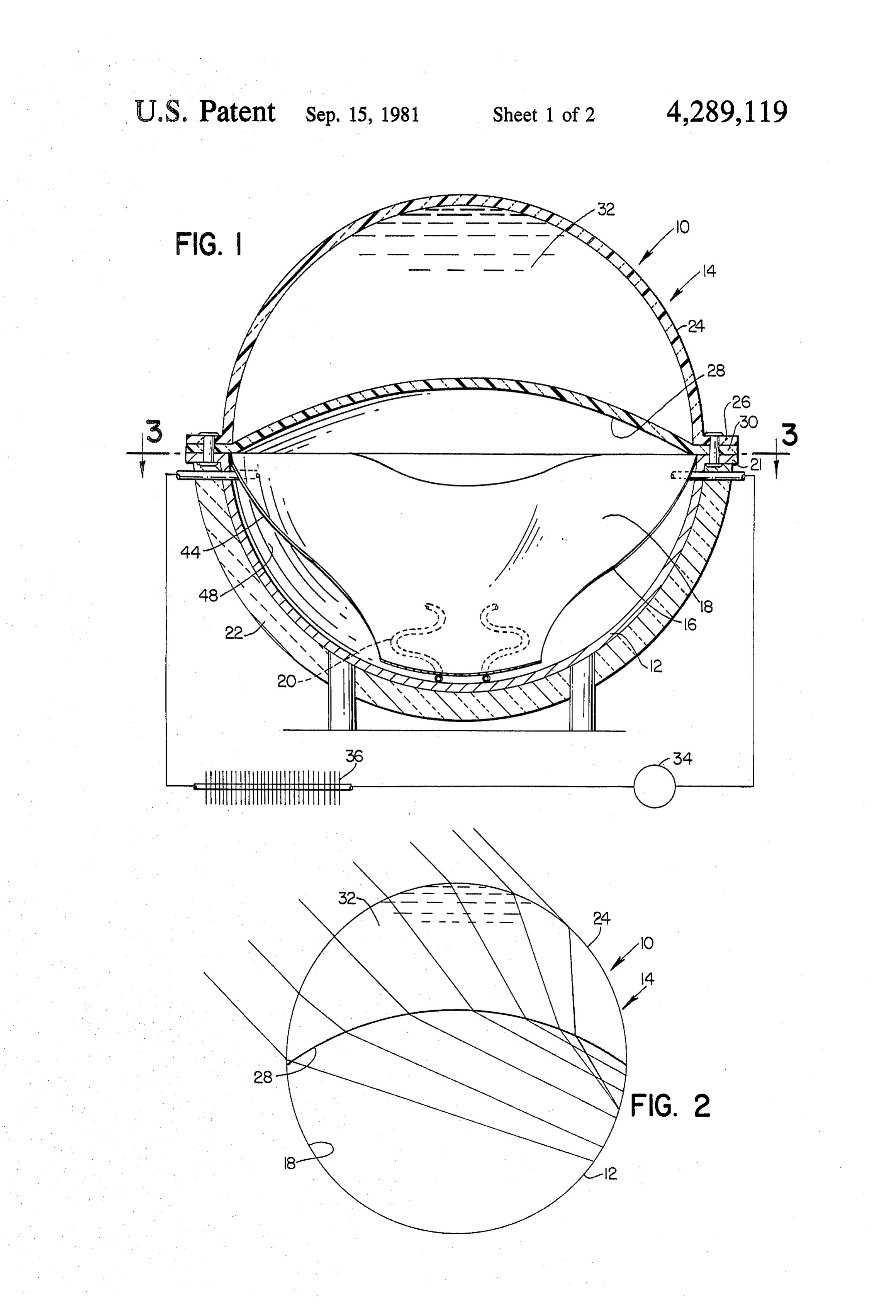
lense means for concentrating solar radiation on an Considering now the illustrated solar collector 10 in energy absorbing surface or the like. further detail and as oriented in FIG. 1, the body 12 Heretofore various solar collectors of non-tracking 10 comprises a generally hemispherical upwardly opening type have been provided for concentrating solar radia shell which has a radially disposed annular flange 21 tion. A collector of non-tracking type is usually surrounding its upper end. The body 12 may be made mounted in fixed position at a predetermined angle of from any suitable material. In accordance with the pres inclination to most effectively receive and collect solar ently preferred practice, however, it is molded from a energy throughout the year. The absorbing surface of 15 suitable plastic material which will withstand tempera such a collector is usually excessively large, to compen tures to which the collector 10 is subjected without sate for the varying position of the sun throughout the distortion. The outer surface of the illustrated body year. Such an arrangement is inconsistent with efficient shell 12 is covered by a layer of insulating material energy exchange. As a result, a considerable amount of indicated at 22. The nature of the insulating material the energy collected may be lost through inefficient 20 and the amount of material required will, of course, be energy exchange and transmission. determined primarily by the anticipated climatic condi Accordingly, it is the general aim of the present in tions to which the collector is to be exposed. vention to provide an improved solar collector of the energy concentrating type wherein the surface area of lense ofillustrated
The lense 14 comprises a concavo-convex fluid body type which includes a generally the absorber is minimized for optimum energy transfer. 25 hemispherical
A further aim of the invention is to provide a durable posed annular outer dome 24, which has a radially dis non-tracking solar collector of the energy concentrat has a radially disposed26, flange and an inner dome 28, which ing type for maximum interception of solar radiation and 30 are sealed together so flange annular 30. The flanges 26 that the inner and outer and low cost manufacture and installation.
30 domes define a chamber 32 which contains a quantity of
SUMMARY OF THE INVENTION lense fluid. Preferably, the fluid which forms the lense In accordance with the present invention an im body will have substantially the same index of refrac proved non-tracking solar energy collector is provided tion as the material from which the lense is made. How with includes a collector body, lense means mounted in ever, the ambient temperatures to which the collector fixed position on the body, and an energy absorber 35 will be subjected will, at least to some degree, deter carried by the body and having an energy absorbing mine the characteristics of the material from which the surface disposed generally within the focal region of the lense is made and the fluid used as a lense body. The lense means. The absorbing surface has a peripheral optical dome or fluid lense may take various optical shape generally defined by the locii of the foci of the forms and may, of course, be made from any suitable sun on the absorbing surface during the days of the 40 materials, however, a plastic material which may be summer and winter solstice when the solar energy col readily molded is presently preferred for convenience lector is mounted in a fixed static position on the earth. and economy of manufacture. Polycarbonate, polyme thelmethacrylate and acrylite plastic, for example, are
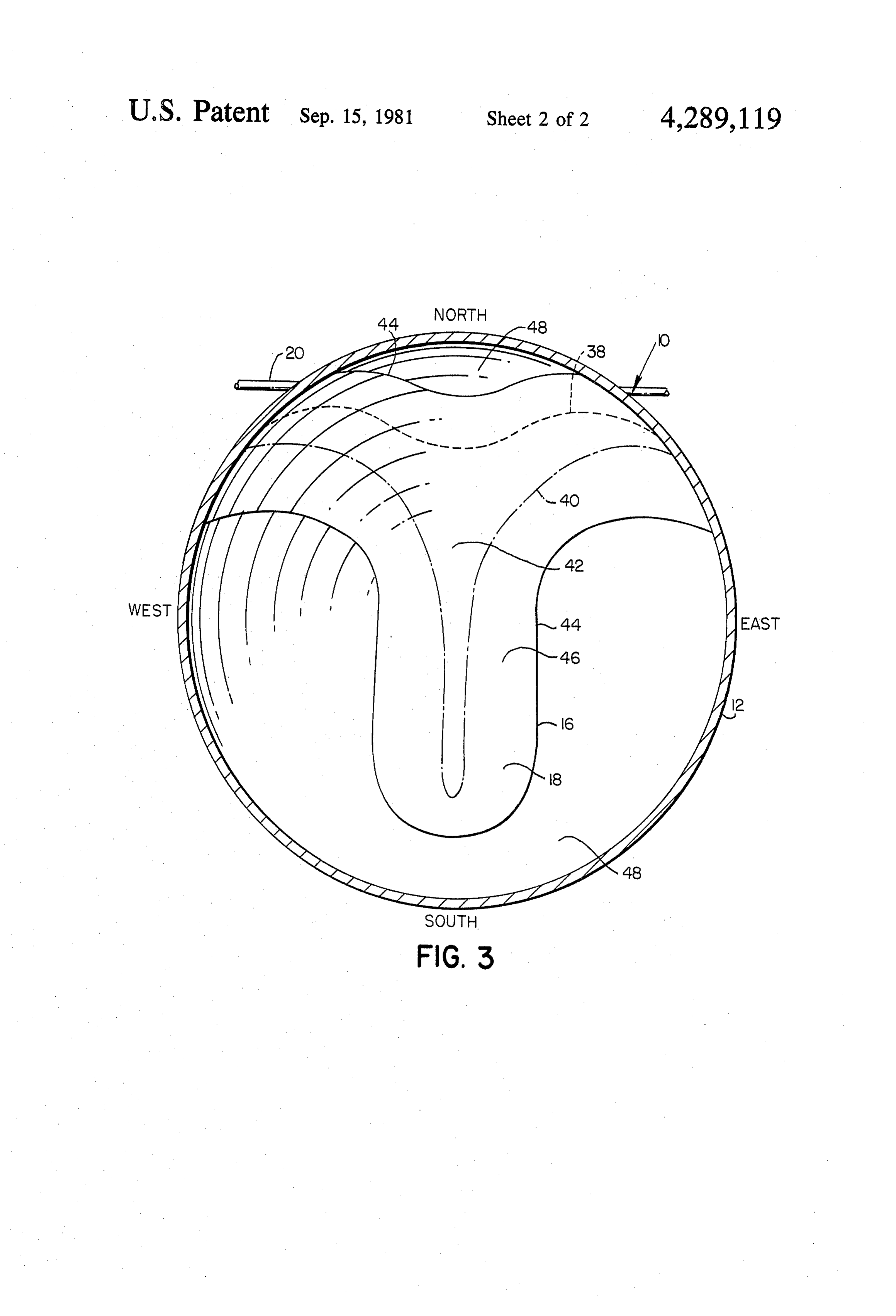
BRIEF DESCRIPTION OF THE DRAWINGS appropriate material for use in making the optical dome. FIG. 1 is a vertical sectional view through a non 45 In accordance with presently preferred practice, how tracking solar energy collector embodying the present ever, the inner and outer domes 28 and 24 are made invention. from Lucite or Plexiglas (refractive index; 1.41), free of FIG. 2 is a diagramatic elevational view of the collec absorbers for maximum energy transmission, and the tor of FIG. 1 and shows ray tracings of oblique rays of lense chamber is filled with ethylene glycol (refractive the sun relative to the collector. 50 index; 1.413). Other lense fluids such as petroleum distil FIG. 3 is a sectional view taken along the line 3-3 of lates, silicone oils and water, may, for example, also be FIG. 1 and shows typical plotted paths of concentration used. A suitable fill plug (not shown) is preferably pro focci as plotted during solar days of the summer and vided to facilitate replenishment of the lense fluid, as winter solstice in any latitude. may be required. A vapor which provides a desired 55 index of refraction under conditions of saturation and
DETAILED DESCRIPTION OF PREFERRED which will not attack the dome material may also be EMBODIMENT appropriate for use as a lense body fluid. Thus, vapors Turning now to the drawings, a solar energy collec such as Freons (KULENE 131-Tri-chlorfluorethane) or tor embodying the present invention and shown in FIG. any other vapor that will provide a desired index of 1 is indicated generally by the reference numeral 10. 60 refraction compatable with a lense dome material on The illustrated collector 10 is of a non-tracking type, complete saturation without attacking the dome mate particularly adapted for mounting in a fixed static posi rial should be suitable. The lense 14 is mounted on the tion on the earth, and has a spherical housing which body 12 with the lense flange 30 in sealing engagement includes a collector body 12 and a lense designated with the body flange 21. Thus, the lense 14 forms a generally by the numeral 14, mounted in fixed position 65 closure for the upper end of the hemispherical body 12. on the body. An energy absorber 16 carried by the body The absorber 16 may comprise a part of the body has an energy absorbing surface 18 within the focal shell 12. In the illustrated embodiment, however, the region of the lense 14. Energy transfer means, such as a absorber 16 comprises a separate parti-spherical plate 5 mounted in the inner surface of the body 12. The parti as the sun moves westward. The resulting curves 38 and spherical suraface 18 is formed to provide full field of 40 generally enclose the entire field of solar energy focus for concentration of radiant energy on the ab concentration, indicated at 42, between December and sorber regardless of the position of the sun. The material June and determine the general peripheral shape of the used to make the absorber 16 preferably has a high ratio absorber 16, as best shown in FIG. 3. Preferably, the of solar absorptivity to infrared emissivity (greater than absorber 16 has an outer peripheral edge 44 which is 5 and preferably near 10 or 12). The absorber may, for defined by the outer edge of a marginal portion 46 example, comprise an aluminum or copper substrate which has an inner boundary formed by the plotted which has a black chrome electroplated absorbing sur curves 38 and 40. The width of the marginal portion is face. Sputtered metal carbide is also appropriate for use O determined by size of the focused images around each as a surface coating material to form a dark energy centroid. The regions of the collector body inner sur absorbing surface on the absorber 16. face beyond the peripheral edge 44 and designated by The energy transfer means 18 preferably comprises a the numeral 48, 48 are not utilized for solar energy network of fluid conduit or tubing welded to the outer absorption. This surface area is preferably provided surface of the absorber 16 for containing a suitable heat 15 with a reflective surface. When the absorber body 12 is transfer fluid. In the illustrated embodiment the tubing made from a plastic material, for example, the surface 48 network 18 is disposed generally between the outer side may have a metalized coating to provide a highly re of the absorber 16 and the inner surface of the body flective surface.
shell 12. The tubing network 18 is shown in FIG. 1 An indicated of the net concentrating power of the connected externally of the body shell 12 in a heat ex 20 illustrated apparatus is provided by the concentration change system which includes a fluid pump 34 and a ratio (CR) defined by the formula:
radiator 36 connected in series in a closed loop. How ever, it should be understood that the collector 10 is CR = Collector Surface Area suitable for use in other types of energy collection and Absorber Surface Area transfer systems, and such other arrangements are con 25 templated within the scope of the invention. wherein the Collector Surface Area is the planar area of In accordance with the present invention, the periph the collector taken at Section 3-3.
eral shape of the absorber 16 is defined by the loci of The illustrated apparatus has an approximate concen the foci of rays of the sun on the absorber surface 18 tration ratio of 1.5. The absorber surface area. 18 is during days of the summer and winter solstice. Typical roughly 65 percent of that of a comparable flat plate ray tracings of direct rays of the sun which pass through collector. The concentration ratio is dependent upon the lense 14 to the absorber surface 18 are shown in the geometry of the lense. A high concentration ratio is FIG. 2 for an oblique angle of incidence (N=45"). The desirable, because absorber surface area is minimized, position of the focused images on the absorber will not thereby, reducing thermal losses and increasing thermal only vary with the angle of incidence but also with the 35 efficiency.
sun hour angle (i.e. the time of day). The sun hour angle The most significant energy losses in the collector 10 varies with the time of the day as the position of the sun will occur in the transmission of direct rays through the changes. The angle of incidence, however, is dependent fluid medium of the lense. These transmission losses will on both the time of the day and the time of the year, be comprised of reflection and absorption losses. How because the earth's orientation to the sun changes 40 ever, these losses are expected to be more than offset by throughout the year. As the sun rises to the east of the the advantages gained through the unique arrangement collector in the morning, the focused image will im of the absorber and the capability of the dome shaped pinge on the west side of the absorber surface 18. At collector lense to intercept solar radiation. solar noon the image will fall on the north-south axis of Although the invention is illustrated with reference the absorber and in the evening the concentrated image 45 to a spherical collector it should now be apparent that will fall on the east side of the absorber. the concepts herein disclosed may also be applied to In northern latitudes in December, the time of the collectors of other shapes, as, for example, cylindrical winter solstice, the sun rises to its lowest position in the collectors utilizing lense means of other optical configu sky, while in June, the time of the summer solstice, it rations, as, for example, aspheric and such modified rises to its highest position. Referring now to FIG. 3, 50 forms of the collector are contemplated within the the concentration foci on the absorber surface 18 is scope of the invention.
plotted for these two yearly extremes in solar orienta In the specification the collector 10 is described as tion, the winter and summer solstice. The plot indicated being mounted in fixed position on the earth, however, by broken lines at 38 illustrates the path of the foci on it should be understood that the collector could also be the absorber surface 18, as viewed from above, during 55 used in a moving vehicle, for example. In such instance the winter solstice whereas the plot indicated by the gyroscopic or gimbal means may be employed to main broken lines designated by the numeral 40 represents tain the collector in a relatively fixed orientation to the the plotted path of the foci of the sun's rays on the surface of the earth and such arrangements are intended absorber surface 18 during the summer solstice. The to fall within the general description "mounted in fixed points used to generate the curves 38 and 40 are deter 60 position on the earth'.
mined from angles measured in ray tracings and from I claim:
angles of known positions of the sun on these two days 1. A solar collector comprising a collector body, (i.e. solar days of the winter and summer solstice). Plot means securing said collector body in fixed and static ted points used to generate the curves shown generally position on the surface of the earth at a fixed latitudinal in FIG. 5 are centroids of focused images of the sun on 65 and longitudinal position, energy absorbing means dis the absorber surface 18. In the morning the focused posed in fixed position on said collector body and hav image of the sun impinges on the west side of the ab ing an energy absorbing surface for receiving and ab sorber and moves eastward along the connecting curve sorbing solar energy, lense means mounted in fixed 6 position on said collector body for continuously focus 10. A solar collector as set forth in any one of claims ingrays of the sun on said absorbing surface throughout 1, 2 or 3 wherein said lense means comprises a concavo the year including the solar days of the summer and convex lense. - winter solstice at said fixed latitudinal and longitudinal 11. A solar energy collector as set forth in claim 3 position, said absorbing surface having a peripheral including energy transfer means disposed in energy shape defined by loci of centroids of the foci of said exchange relation with said energy absorbing surface.
solar energy collector as set forth in claim 11 rays of the sun focused on said absorbing means by said wherein said energy absorbing means comprises a plate lense means during said solar days of the summer and defining said energy absorbing surface and said energy winter solstice as determined by the fixed and static O transfer means comprises a network of fluid conduit position of said collector body at said fixed latitudinal disposed in contact with said plate. and longitudinal position. 13. A solar collector comprising a collector body, 2. A solar energy collector as set forth in claim 1 means securing said collector body in fixed and static wherein said absorbing surface has a peripheral edge position on the surface of the earth at a fixed latitudinal defined by the outer edge of a marginal portion of said 15 and longitudinal position, said collector body including surface, said marginal portion having an inner boundary a generally hemispherical upwardly opening shell hav defined by said locii of said centroids of said foci. ing a generally hemispherical inner surface, energy absorbing means disposed within said shell for receiving 3. A solar energy collector as set forth in either claim and absorbing solar energy and having an energy ab 1 or claim 2 wherein said lense means comprises a fluid sorbing surface partially defining said hemispherical lense. inner surface, concavo-convex lense means mounted on 4. A solar energy collector as set forth in claim 3 said collector body for continuously focusing rays of wherein said lense means and said collector body coop the sun on said absorbing surface throughout the year erate to define a housing having a chamber therein and including solar days of the summer and winter solstice said absorbing means is located within said chamber. 25 at said fixed latitudinal and longitudinal position, said 5. A solar energy collector as set forth in claim 4 lense means forming a closure for said upwardly open wherein said housing has a generally spherical configu ing shell, said shell and said lense means cooperating to ration. define a chamber containing said energy absorbing 6. A solar energy collector as set forth in claim 4 30 means, said absorbing surface having a peripheral shape defined by locii of centroids of the foci of said rays of wherein said absorbing means comprises a plate the sun focused on said absorbing surface by said lense mounted in fixed position within said chamber and de means during said solar days of the summer and winter fining said absorbing surface. solistice as determined by the fixed and static position of 7. A solar energy collector as set forth in claim 6 said collector body at said fixed latitudinal and longitu wherein said energy absorbing surface defines a portion 35 dinal position.
of the inner surface of said collector body and the re 14. A solar collector as set forth in claim 13 wherein maining portion of said inner surface comprises an en said concavo-convex lense means comprises a fluid ergy reflecting surface. lense including a lense shell and a quantity of fluid con 8. A solar energy collector as set forth in claim 3 tained within said shell.
wherein said lense comprises a shell containing a quan wherein15. A solar energy collector as set forth in claim 14 said fluid has an index of refraction substan tity of fluid and the index of refraction of the material tially equal from which said shell is made is substantially equal to to the index of refraction of said lense shell. the index of refraction of said fluid. 16. A solar energy collector as set forth in any one of claims 13 through 15 wherein said absorbing means 9. A solar energy collector as set forth in claim 3 45 comprises a parti-spherical plate mounted within said wherein said lense comprises a plastic shell containing a chamber.
quantity of ethylene glycol. : k : k
Provenance
- Collection
- Patents citing this work
- Pages
- 6
- Method
- pdftotext (the PDF's own text layer) + pdftoppm 300dpi page scans
- Patent office record
- patents.google.com →
- Source
- Google Patents citing-documents table
- Assignee
- Soloptics, Inc.
- Published
- 1981-09-15
- Transcribed from
- patentimages.storage.googleapis.com →