

patent · US4293196A
Objective lens system with aspheric Fresnel elements
6 October 1981
Text
Page 1scan →
350-452 SR
Hilbert
(54) objective lens system with
Aspherc fresnel elements
(75) Inventor: Robert S. Hilbert, La Canada, Calif. 73) Assignee: Fantacia, Del Mar, Calif.
52 U.S. Cl. .................................... 350/452; 350/432;
3,909,525 9/1975 Fagan .............................. 350/211 X
Primary Examiner-John K. Corbin
Assistant Examiner-Scott J. Sugarman
Attorney, Agent, or Firm-Jackson, Jones & Price
A high speed projection lens system particularly adapt able for a television projection system having a viewing screen and a video image forming surface is provided. The projection lens system includes a first thin meniscus lens element convex to the projection screen having an aspherical Fresnel type surface; a second thin meniscus lens element concave to the projection screen having an aspherical Fresnel type surface and a weak third thin aspherical meniscus lens element.
31 Claims, 25 Drawing Figures
Drawings
Page 2drawing sheetscan →
Page 3drawing sheetscan →
Page 4drawing sheetscan →
Page 5drawing sheetscan →
Page 6drawing sheetscan →
Page 7drawing sheetscan →
Page 8scan →
thickness. By maintaining this thin configuration for
OBJECTIVE LENS SYSTEM WITH ASPHERIC each of the lenses, it is possible to commercially manu FRESNEL ELEMENTS facture these lenses at a relatively low cost. The desired speed of the lens system is in the range of F/2.5 to
Background of the invention 5 f/o.7
1. Field of the Invention The preferred embodiments disclosed herein utilize The present invention relates to a high speed, objec one aspheric fresnel surface and one classical spherical tive optical system of an economical construction and surface on each of two or more airspaced elements. In more particularly a multi-element thin objective system 10 one embodiment, three aspherical Fresnel type surfaces capable of providing video projection. are provided on the projection screen side of the lens 2. Description of the Prior Art elements. In another embodiment of the present inven Since approximately the invention of television, at tion, the projection screen side of the third meniscus tempts have been made to increase the size of the view lens element has a smooth aspherical shape. ing picture. Simple glass magnification lenses were ini The present invention is designed for use with a video tially introduced to directly enlarge the size of the im 15 imaging system such as television and can be sold as a ages on the cathode tube with the viewer observing the video projection system for incorporation with a resi object side of the lens. Improvements in the resolution dential television set. The video projection system in and size of cathode tubes made these early efforts obso cludes the objective projection lens assembly which can lete. be mounted in front of the television screen, appropriate Recently, various forms of television projection lens 20 electronics to invert the image on the television screen, systems have been suggested. These T.V. projection and a projection screen which can be appropriately systems have become popular particularly in commer positioned relative to the lens assembly. The projected cial environments and to a lesser degree in individual image magnification ratio achieved is approximately a residences. A prime problem for universal acceptance revolves about the factors of cost and image quality. 25 factor of five while maintaining adequate illumination The aberrations created in the magnification of the design fieldresolution and image of view.
with minimal distortion within the image during projection have required relatively expen The features of the present invention which are be sive solutions.
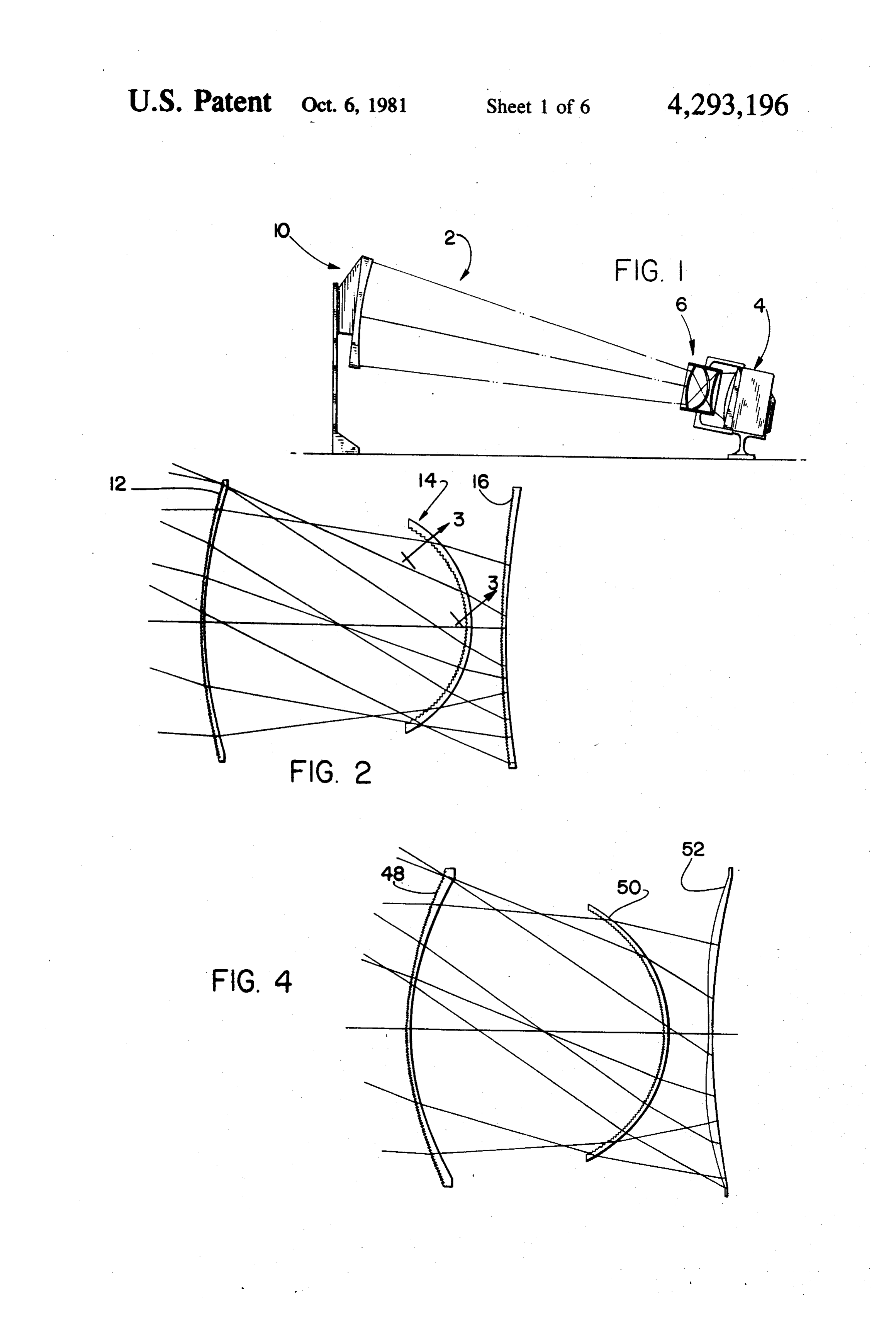
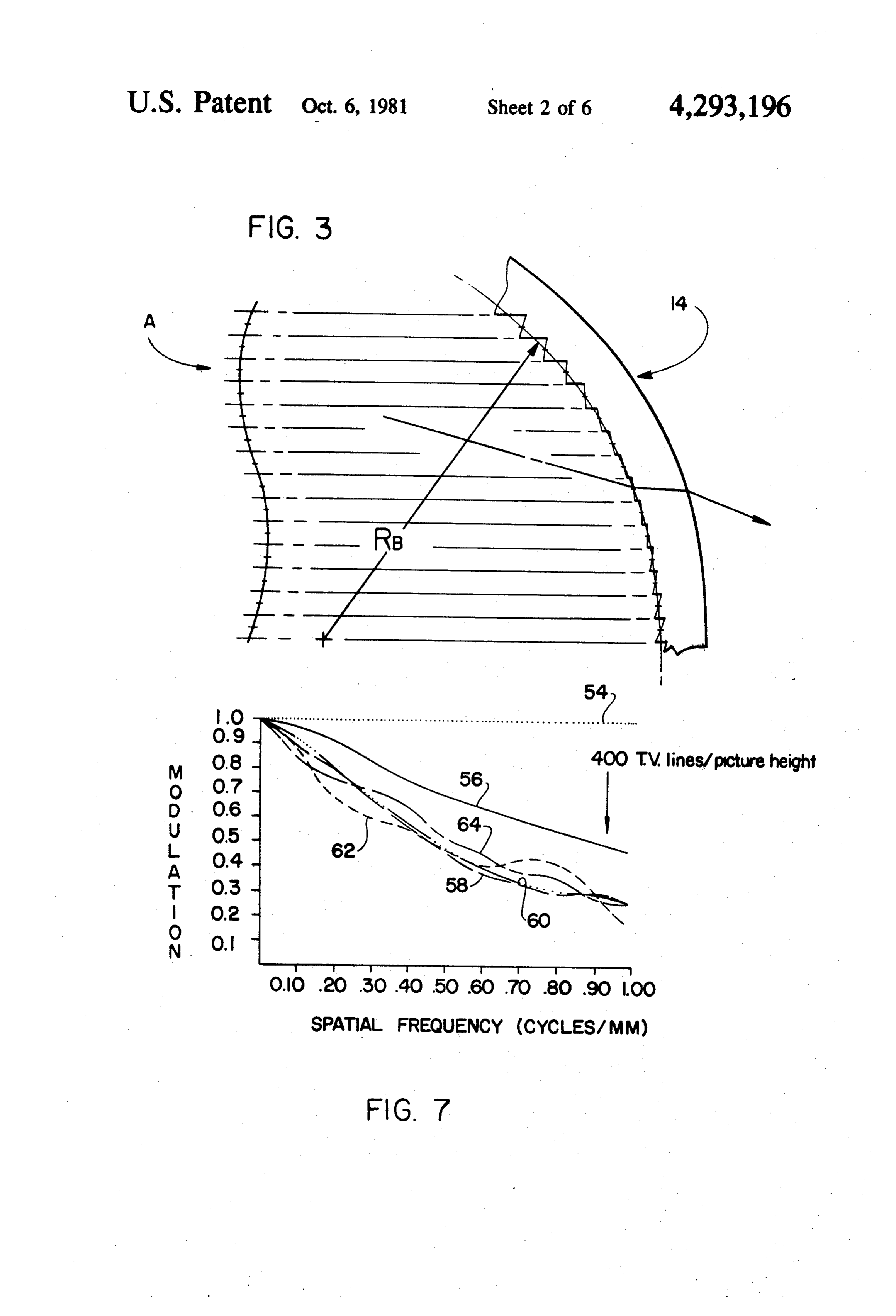
A popular, but expensive, approach has been called a lieved to be novel are set forth with particularity in the Schmidt system since it utilizes a Schmidt catadioptric 30 appended claims. The present invention, both as to its organization and manner of operation, together with objective system. The complimentary video system for further objects and advantages thereof, may best be the Schmidt system is specifically designed as an inte understood by reference to the following description, gral component and it is possible to drive its cathode taken in conjunction tube to temperatures beyond those permitted on a nor with the accompanying drawings. mal television set to increase the illumination. 35 BRIEF DESCRIPTION OF THE DRAWINGS Recently, a triplet objective system with aspheric surfaces has been suggested. The lens elements of this FIG. 1 is a schematic view of a television projection system are formed from plastic and are relatively thick system of the present invention; requiring special efforts during production with result FIG. 2 is a schematic cross-sectional view of a first ing costs. - embodiment of the lens design; Various types of curved Fresnel lenses for special FIG. 3 is an explanatory schematic view of a portion optical applications have been suggested in the optical of the meniscus lens element with a Fresnel type aspher field and are cited of general interest such as U.S. Pat. ical surface;
Nos. 3,653,751; 3,572,903 and 3,523,721. FIG. 4 is a schematic cross-sectional view of a second The prior art is still striving to provide a relatively 45 embodiment of the lens design with two Fresnel type inexpensive objective lens system that can be mounted surfaces;
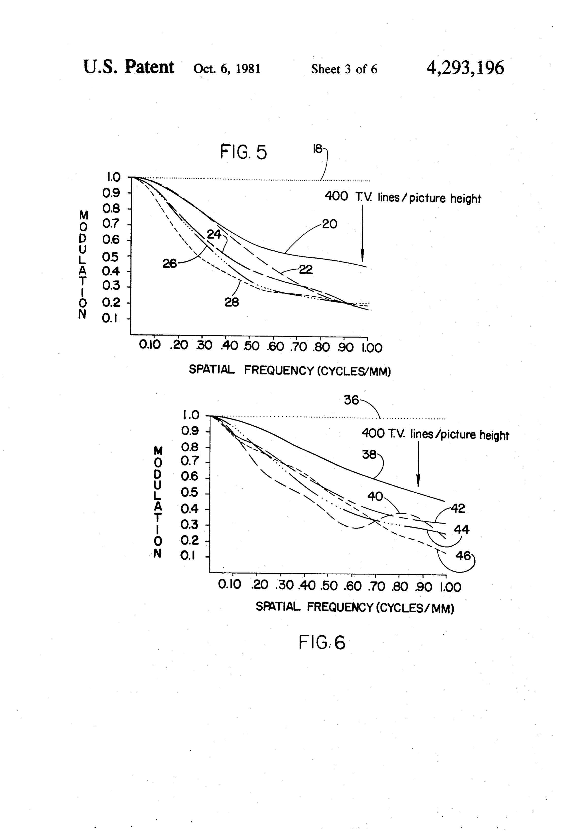
on the average television set to provide a magnified FIG. 5 is a graph of the geometrical MTF for the lens projection of the video images onto a viewing screen design of FIG. 2;
with acceptable image resolution. FIG. 6 is a geometrical MTF curve for the lens de 50 sign of FIG. 4.
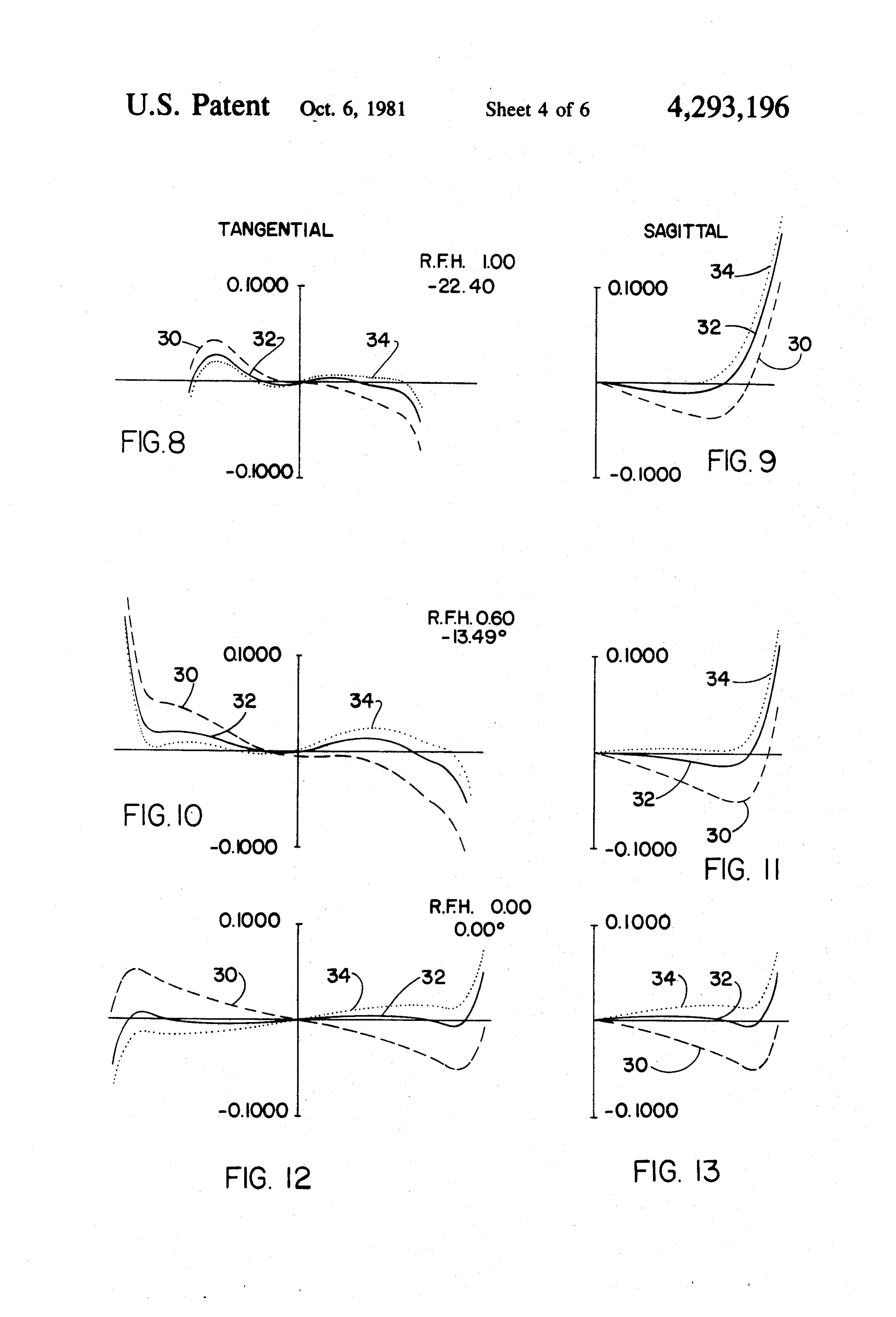
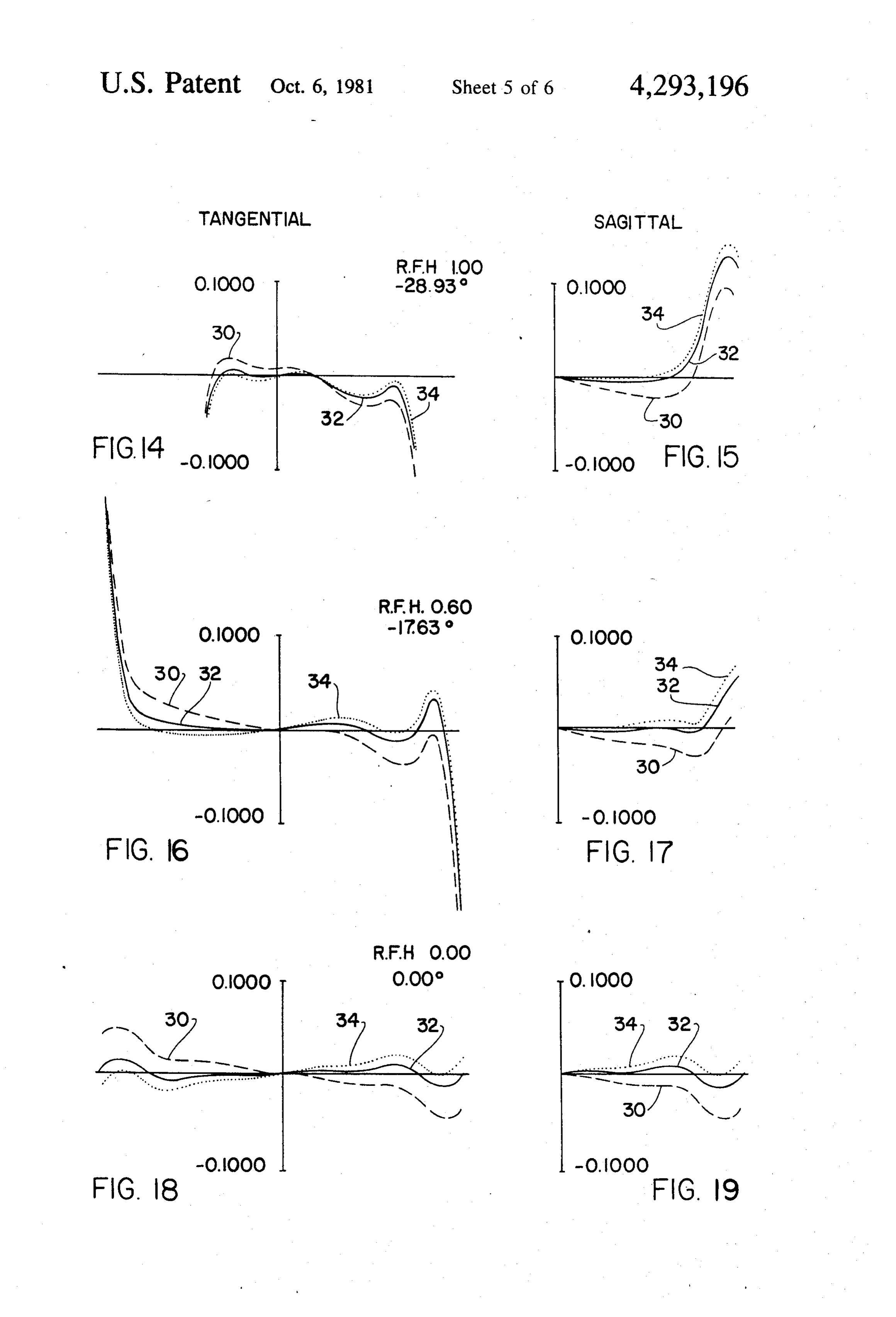
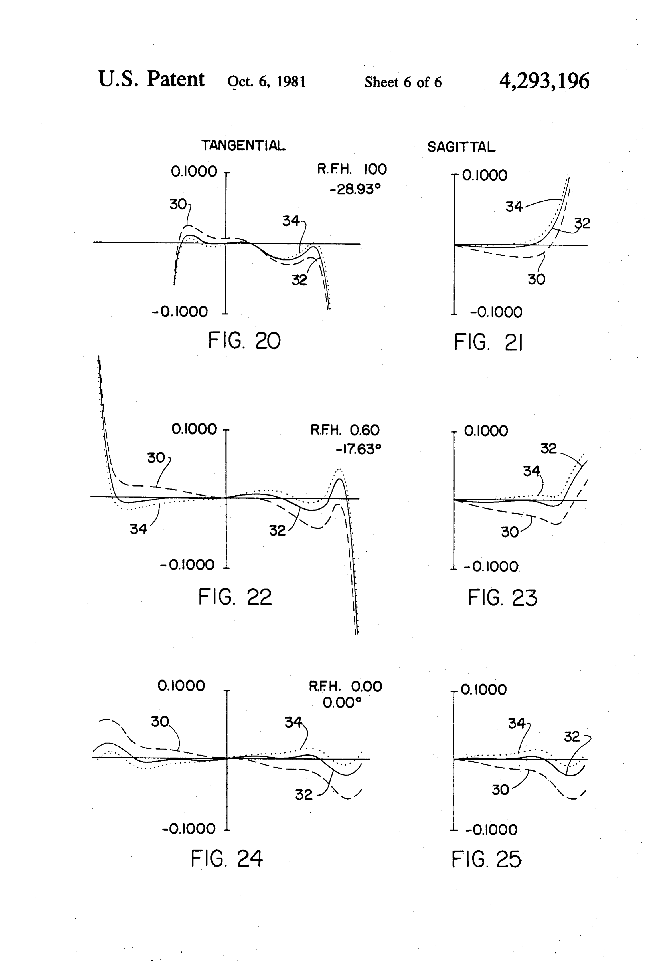
SUMMARY OF THE INVENTION FIG. 7 is a geometrical MTF curve for a third em The present invention is directed to a high speed bodiment of the present invention; objective lens system that is particularly adaptable for a FIGS. 8 through 13 are the tangential and sagittal television projection system. The lens system includes transverse aberration curves for the first embodiment of from an object projection screen to a video image sur 55 the present invention;
face, a first thin meniscus lens element convex to the FIGS. 14 through 19 are the tangential and sagittal screen side having an aspherical Fresnel type surface on transverse aberration graphs for a second embodiment the screen side and a smooth radius surface toward the of the present invention, and video image side; a second thin meniscus lens element FIGS. 20 to 25 are the tangential and sagittal trans concave to the screen side with a Fresnel type surface 60 verse aberration graphs for a third embodiment of the on the screen side, and a smooth radius surface toward present invention disclosed in FIG. 4. the image side, and a third thin aspheric meniscus lens DESCRIPTION OF THE PREFERRED element convex toward the screen side. Each of the lens elements are manufactured from a plastic material such EMBODIMENTS as methacrylate. The thickness of each lens, while vary 65 The following description is provided to enable any ing from its thickness at the optical axis, is relatively person skilled in the optical and video field to make and uniformly thin and the effective diameter of each lens is use the invention and sets forth the best modes contem at least twenty times greater than the lens' maximum plated by the inventor of carrying out his invention.
Page 9scan →
Various modifications, however, will remain readily non-flat or curved base, aspheric Fresnel type of lens apparent to those skilled in the art since the generic assists in the correction of coma and other aberrations principles of the present invention have been defined which is not possible with a flat classic aspheric Fresnel herein specifically to provide a relatively economical lens. Preferably the Fresnel facet width is selected in an and easily manufactured optical video projection sys intermediate range between that of a very fine spacing, tem for sale as an accessory to a television set or as a e.g. 0.005 inch and very coarse spacing, e.g. 0.10 inch, component in a video projection system. The construction of the desired Fresnel type surface Referring to FIG. 1, a schematic video projection involves superimposing segmented sections of the slope system 2 is disclosed. A television set 4 such as a 13 inch of an aspherical curve, A, on a spherical base of a prede diagonal color television set that can be commercially O termined radius, RB. As can be seen from FIG. 3, an purchased from numerous manufacturers can be uti aspherical curve is segmented and each segmented por lized. While not shown a standard electronic accessory tion is a refracting facet of the Fresnel type surface. item is attached to the television set to invert the image Thus, these segmented slopes are superimposed on the formation on the screen. A high speed objective lens lens face with the radius, RB, passing through each system 6 is mounted in front of and spaced from the 15 median point. As a result the locus of median points of image forming surface of the television set 4 by appro the respective step facets form a non-planar configura priate mounting brackets 8. A curved viewing screen 10 tion. A classical Fresnel surface would result for the is located approximately eight feet from the television case where, RB, was equal to infinity. As can be appre set 4. As can be readily appreciated, the schematic view ciated by an optical designer an approximation could be of FIG. 1 is not drawn to scale. The diagonal of the 20 achieved with a single continuous surface to facilitate a viewing screen 10 is approximately 63 inches with a molding process.
concave radius of approximately 130 inches. While a The resulting optical design includes the following curved viewing screen 10 is disclosed, it should be ap characteristics of at least one Fresnel type surface on preciated that other geometrical shapes, such as flat, can one lens element; two or more refractive meniscus lens be utilized with appropriate modification of the optics 25 elements that are capable of forming an image, one of the present invention. convex and one concave towards the projection screen; An important feature of the present invention is to the lens elements are thin having approximately uni provide a relatively inexpensive objective lens system form thickness throughout the height of the lens, e.g. a to permit the average consumer to purchase the same. thickness to diameter ratio of less than 1 to 20 and the Specially designed video projection systems are capable 30 Fresnel type base radius, RB, should be in the range of of providing a higher illumination level but only at a 0.53 to 20 times the diameter of its optical element. relatively prohibitive cost to the average consumer. Referring to FIG. 2, a first embodiment of the objec The design goals of the present invention is to provide tive lens system 6 is disclosed. A first thin meniscus lens an acceptable image resolution at a relatively low cost. element 12 is convex to the projector screen. The tradi To achieve this goal, certain design constraints were 35 tional left or object side being defined herein as the side assumed such as the necessity to utilize plastic molded of the projection screen 10. The first surface has Fresnel lenses to permit a relatively inexpensive production of type facets with aspherical slope superimposed on a aspherical lenses capable of providing additional param non-flat base radius, RB. The base radius can be defined eters to correct the aberrations that were believed to be as the locus of the median point of each step or facet of intrinsic in the design. By providing relatively thin plas the Fresnel type surface. The Fresnel type surface is tic lenses the design goal of efficient mass production is provided to increase the refractive power of the lens believed to be obtainable. It is also a goal of the present while permitting correction of coma and other aberra invention to provide a relatively high speed lens within tions. The right side of lens element 12 is spherical and the range of F/2.5 to F/0.7. Such a high speed lens is can be coated with an anti-reflection coating such as necessary to provide the maximum illumination to the 45 magnesium fluoride. This coating would increase the projected image. transmission of light through the lens element by reduc During the initial analysis of the lens design it became ing the degree of reflection loss across the bandwidth of apparent that to achieve a television projection lens visible light. A second thin meniscus lens element 14 is having the desired speed that the number of thin con concave to the left side of FIG. 2. Again, the left side of ventional plastic lens elements required while maintain 50 lens element 14 has an aspherical Fresnel type surface ing a minimal thickness would fall within the range of on a non-flat base radius. An enlarged view of a portion six to ten lens elements. The potential reflection loss for of lens element 14 is schematically set forth in FIG. 3. each surface of these lens elements plus the complexity The base radius, RB, is schematically disclosed as the of mounting the lenses would defeat the principle goal locus of the medium point of each facet step of the of the invention design. To eliminate this problem the 55 Fresnel type surface. The specific aspherical equation use of a non-flat Fresnel type lens surface is utilized. and coefficients are set forth subsequently in Table 1 to The extreme curves utilized in the lens design created derive curve A.
an initial concern as to reflection loss at high incidence Finally, a third thin meniscus lens element 16 having angles. However, since the major percentage of each a relatively weak power and convex to the left side lens surface has less than a 45-degree incident angle the completes the first lens system. Again the left side of reflection loss was controlled to a tolerable level. In lens element 16 has an aspherical Fresnel type surface. addition, it is within the parameters of the present in The right side of both lens elements 14 and 16 are vention to provide an anti-reflection coating such as smooth and could be coated with an anti-reflective magnesium fluoride on the non-Fresnel surfaces to material to improve the light transmission through the thereby increase the transmission of light. By resorting 65 lens system.
to the Fresnel type surface a greater refracting power This first embodiment of the present invention has a can be provided while still maintaining a relatively thin speed of F/1.56 and provides a curved Fresnel type lens that can be molded on a commercial basis. The triplet having good control of both distortion and image 10 quality. The effective diameter of each lens in this first entrance pupil diameter is 8.5 inches with an exit pupil embodiment is at least twenty times greater than the diameter of 7.8 inches. The clear aperture of the outer maximum thickness of the lens. The thickness of the lens element, 12, is approximately 9.5 inches. Finally, lenses along the optical axis are only 0.09 inches as can the relative illumination at the corner of the screen due be seen from the following Table 1. 5 to vignetting of the lens barrel was approximately 47 In the design of the following lens system, the specific percent. The lens barrel length, from vertex to vertex lens parameters were derived after a consideration of was approximately li inches and is positioned approxi both optical image quality and economic factors. In the mately 8.2 inches away from the surface of the image lens drawings of FIGS. 2 and 4 which support the speci- forming screen of the television set 4. The preferred fication and supplement the parameters of the lens sys- 10 plastic material was methacrylate, although other types tem as set forth in the following Tables, the lenses in of plastic could be used such as styrene for one or two accordance with the present invention, are illustrated lens elements with a slight redesign. diagrammatically. As usual, in conventional lens dia- The geometrical MTF discloses a resolution capabil grams, the axial spacings are measured from left to right ity across the field of approximately 400 T.V. lines per with consecutive numbers. Additionally, the radius of 15 picture height and is set forth in FIG. 5. In calculating curvatures are directional in the Tables in sequence these MTF curves, a wavelength weight factor of 1 was from left to right. The symbols of axial spacings (both assigned to wavelengths of 656.3 nm and 486.1 nm air spaces and lens thicknesses) and radius of curvatures while a factor of 2 was assigned to a wavelength of have been omitted from the drawings for the sake of 587.6 nm. In the MTF graph, the diffraction limit is clarity in view of the ray traces which are believed to 20 disclosed as line 18 while the axis is disclosed as line 20. provide additional information to an optical designer A tangential curve 24 and a sagittal curve 26 are set skilled in this field. forth for a 0.6 field height (-13.49 degrees) and a tan In the Tables, the minus signs (-) indicate surfaces gential curve 22 and a sagittal curve 28 is set forth for a concave toward the left side of the drawings, while the 1.0 field height (-22.40 degrees). surfaces without the sign are convex toward the left 25 Three aberration graphs for respectively relative side. The Tables also disclose the axial spacings along field heights of 1.00, 0.60 and 0.00 are set forth, for the optical axis and include both the axial spacings be- tangential aberrations in FIGS. 8, 10 and 12 and for the tween the lens elements and the thickness of the lens sagittal aberrations in FIGS. 9, 11 and 13 for the first elements. The axial spacings between the lens elements embodiment. Curve 30 is for a wavelength of 486.1 nm are positioned accordingly, relative to the radii in the 30 while curve 32 is for a wavelength of 587.6 nm and Tables while the thicknesses are designated accord- curve 34 is for a wavelength of 658.3 nm. The same ingly, on the same line as the radii. The dimensions in wavelength values are presented by the same form of . the Tables are given in inches, however, it should be curve in each of the aberration graphs. All aberrations readily appreciated that the actual linear dimensions can in these graphs are scaled in inches. be scaled to values with reference to an equivalent focal 35 A distortion of less than 0.2 inches was achieved on length of unity. The Tables also provide with respect to the projection screen. This distortion represents the each example, the Abbe number and index of refraction. maximum sag perceived from a viewing position near Finally, the Tables provide the aspheric constants for the lens for a projected straight line at the top of the deriving the aspheric slope for the Fresnel facets along T.V. screen. The relative illumination at the corner of with the base radius, RB. 40 the projection screen due to vignetting is approximately
Table
ELEMENT R1 R2 T N/v
Object distance 73.5468
L A(1) 3.5990 O900 1491/57.2
Aperture stop
L2 A(2) - 4.397 0900 1.491/57.2
L3 A(3) 26,0000 0900 1.49/57.2
Image 8.2004
Aspheric constants
Aspherec curve k a b
A(1) 1708.6590 0000000 -3.65390E - 4 -2.22403E - 5
A(2) -07207025 0000000 - 702038E -3 --2.17572E - 4
A(3) -.04295470 0.000000 5.87983E-3 -3.05549E - 4.
In the first embodiment, the radius of the screen was 65 assumed to be 129.87 inches with a total field angle of approximately 45 degrees. The back focal length is 8.2 inches with an effective focal length of 13.3 inches. The 47 percent.
Page 11scan →
A second embodiment of the present invention is Again, a distortion of less than 0.2 inches is achieved disclosed in the following Table 2. The relative shape of on the projection screen while the absolute illumination the lens elements are somewhat similar to that disclosed at the projection screen is less than for the first embodi in FIG. 2 and accordingly, are not illustrated since it ment, it is still adequate if the ambient illumination at would appear to a large degree as a duplication of the 5 the projection screen has a relatively low light level. As lens schematic of FIG. 2. can be readily appreciated the apparent image bright
Table 2
Element r r2 t n/v
Object distance 57.440
Aperture stop
Image 8.0552
Aspherc constants
Z= curvy -- (a)y + (b)y6+ (c)y8 + (d)y10
Aspheric curvature k a. b
A(1) .2838024 0.000000 - 9.31229E - 4 - 5.36759E - 4
A(2) -12935331 0.000000 - 1852.53E-2 7.55302E - 4
A(3) -03561578 ooooooo 1.44629e - 2 - 1637.79e-3
The second embodiment of the present invention has ness is a function of the ambient illumination of the a speed of F/1.9 and again provides a meniscus Fresnel projection screen for each of the designs presented type triplet having good control of both distortion and herein. That is the optimum results will be perceived by image quality. As with the first embodiment, the thick a viewer sitting adjacent the television in a relatively ness of the lenses along the optical axis are only 0.09 35 darkened room. In the second embodiment the relative inches and the ratio of the lens diameter to maximum illumination for a field of 0.6 was 77 percent. thickness is maintained at less than a factor of 20. The A modified version of the second embodiment of the field angle has been increased to approximately 58 de present invention is disclosed in FIG. 4. It is believed grees and the back focal length is 8.06 inches with an that this third embodiment is less difficult to fabricate effective focal length of 10.1 inches. The entrance pupil than the second embodiment since the flattest aspheric diameter is 5.3 inches with an exit pupil diameter of 5.2 Fresnel lens element has been redesigned as a classical inches. The clear aperture of the outer lens element, aspheric lens element. As can be determined, the same closest to the projection screen, is approximately 6.2 maximum lens thickness parameters have been main inches. tained in this third design. The relative illumination at the corner of the screen 45 A first thin meniscus lens element 48d is convex to the due to vignetting of the lens barrel is approximately 32 projection screen with a first surface having Fresnel percent. The lens barrel length, from vertex to vertex is type grooves with superimposed aspherical sloped fac approximately 6.5 inches and is positioned approxi ets on a non-flat base radius, RB. The right side of lens mately 8 inches away from the television screen. Again, element 48 is smooth and can be coated with an anti the preferred plastic material is methacrylate although 50 reflection coating. A second thin meniscus lens element other types of plastic such as styrene can be used with a 50 is concave to the left side of FIG. 4 and the left slight redesign. surface of lens element 50 has an aspherical Fresnel type The geometrical MTF for the second embodiment is surface. Finally, a third thin meniscus lens element 52 disclosed in FIG. 6 and is derived in a similar manner as having a relatively weak power and convex to the left was disclosed with respect to the first embodiment. In 55 side completes the third embodiment. The left side of the MTF graph of FIG, 6, the diffraction limit is dis lens element 52 has a classical aspherical surface. The closed as line 36 while the axis is disclosed as line 38. A right side of each of the lens elements 48, 50 and 52 are tangential curve 42 and a sagittal curve 44 are set forth smooth and spherical and could be coated with an anti for a 0.6 field height (-1763 degrees) and a tangential reflection material.
curve 40 and a sagittal curve 46 is set forth for a 1.0 field 60 This third embodiment of the present invention has a height (-28.93 degrees). speed of F/1.9 with a total field angle of approximately Aberration graphs for respectively relative field 58 degrees. Again, the effective diameter of each lens in heights of 1.00, 0.60 and 0.00 are set forth in FIGS. 14 this third embodiment is at least 20 times greater than to 19. Tangential aberrations are disclosed in FIGS. 14, the maximum thickness of the lens and the Fresnel base 16 and 18 while sagittal aberrations are disclosed in 65 radius, RB, is in the range of 0.53 to 20 times the diame FIGS. 15, 17 and 19. The graph symbols of each respec ter of its respective optical element. The thickness of tive curves again corresponds to the same wavelengths the lenses along the optical axis are only 0.09 inches. As defined per curves 30, 32 and 34 of FIG. 8. with each of the lens designs presented herein the pro 12 jection screen radius is assumed to be 130.0 inches. The a first thin meniscus lens element convex to the object back focal length is 8.05 inches with a focal length of a side having a curvilinear configuration on one side 10.1 inches. The entrance pupil diameter is 5.3 inches and a Fresnel type surface on the other side; with an exit pupil diameter of 5.2 inches. The clear a second thin meniscus lens element concave to the aperture of the outer lens element, 48, is approximately 5 object side having a curvilinear configuration on 6.4 inches. The relative illumination and distortion is one side and a Fresnel type surface on the other approximately the same as the second embodiment. The side, and specific parameters of this third embodiment is set forth a third weak thin aspherical meniscus lens element in Table 3 as follows: convex to the object side.
Table 3
Element r r2 t n/v
Object distance 57.4401
Ll A(l) 5.3957 0.900 1.491/57.2
Aperture stop
L2 A(2) -2.7674 0900 1.491/S7.2
L3 A(3) 13.2925 O900 - 1.491/57.2
Image 8,0534
Aspherec constants
Z= curv)y + (a)y + (b)y6 + (c)y8 + (d)y10
Aspheric curvature k a b
A(1) .28380247 0.000000 -9.31229E - 4 - 5.36759E - 4
A(2) -.12935331 0.000000 -1.852.53E -2 7.55302E - 4
A(3) -.03580302 0.000000 46732E -2 - 1.67730E-3
2. The invention of claim 1 wherein each of the Fres
The geometrical MTF for the third embodiment is 35 nel surfaces have a locus of median points of their re again derived in the same manner mentioned above spective step facets that form a nonplanar configuration. with respect to the other MTF graphs is disclosed in 3. The invention of claim 1 wherein the object side of FIG. 7. In the MTF graph of FIG. 7, the diffraction the third lens includes an aspherical surface. limit is disclosed as line 54 while the axis is disclosed as 4. The invention of claim 1 wherein the third lens has line 56. A tangential curve 58 and a sagittal curve 60 are one surface having a curvilinear configuration on one set forth for a 0.6 field height (-17.63 degrees) and a side and a Fresnel type surface on the other side. tangential curve 62 and a sagittal curve 64 is set forth 5. The invention of claim 1 wherein the effective for a 1.0 field height (-28.93 degrees). diameter of each lens is at least twenty times greater The aberration graphs for respectively relative field than its maximum thickness.
heights of 1.00, 0.60 and 0.00 are set forth in FIGS. 20 45 6. The invention of claim 1 wherein the slopes of step to 25. The tangential aberrations are set forth respec facets forming the Fresnel surfaces are aspherical. tively in FIGS. 20, 22 and 24, while the sagittal aberra 7. The invention of claim 1 wherein each lens element tions are set forth in FIGS. 21, 23 and 25. Again, the has the same thickness on the optical axis. symbols for the respective curves are consistent with 8. The invention of claim 1 wherein each lens is the wavelengths designated in FIG.8. 50 formed from a plastic material. While the above examples provide the preferred em 9. The invention of claim 8 wherein each lens is bodiments of the present invention and it is believed formed from an acrylic plastic.
that the third embodiment described above is the least 10. The invention of claim 1 wherein the speed of the expensive to manufacture, it should be readily apparent lens system is greater than or equal to F/1.9. that these examples are simply illustrative of the broad 55 11. In a video projection system having a projection principles of the present invention and are not to be screen and an image forming surface, the improvement construed as limiting. It is believed that the present comprising;
invention discloses a unique application of a Fresnel a high speed objective projection lens assembly oper type aspheric facet lens on a thin non-planar base that atively positioned relative to the image forming has not been heretofore provided in the optical field. 60 surface for projecting the images onto the screen Accordingly, the scope of the present invention should including a first thin meniscus lens element convex be determined solely from the following claims. to the projection screen, a second thin meniscus What is claimed is: lens element concave to the projection screen, and 1. A high speed objective lens system capable of a third thin lens element, at least one surface on forming images that is particularly adaptable for a tele 65 each of two lens elements have a Fresnel type vision projection system comprising from a viewing surface, the locus of median points of respective screen object side to a video image side on an optical step facets of each Fresnel type surface forming a aX1s; nonplanar configuration.
Page 13scan →
12. The invention of claim 11 wherein the slopes of 20. The invention of claim 19 wherein the locus of the step facets of the Fresnel surface are aspherical. median points traces a cross-sectional circular path. 13. The invention of claim 11 wherein each of the 21. The invention of claim 19 wherein the slopes of meniscus lens elements have one aspherical Fresnel step facets forming each Fresnel surface is aspherical. facet surface. 5 22. The invention of claim 19 wherein the lens ele 14. The invention of claim 11 wherein the effective ment is molded from a plastic material. diameter of each lens is at least twenty times greater 23. The invention of claim 19 wherein the object side than its maximum thickness. surface of the third lens element is convex to the image 15. The invention of claim 11 wherein each lens ele- side.
ment has the same thickness on the optical axis. 10 24. The invention of claim 19 wherein the effective 16. The invention of claim 11 wherein each lens is diameter of each lens is at least twenty times greater formed from a plastic material. than its maximum thickness, 17. The invention of claim 11 wherein the speed of 25. The invention of claim 24 wherein each Fresnel the lens system is greater than or equal to F/1.9. refracting surface is aspherical. 18. The invention of claim 16 wherein each lens is 15 26. The invention of claim 25 wherein at least one formed from an acrylic plastic. refracting surface on each lens element is aspherical. 19. A high speed plastic objective lens system com- 27. The invention of claim 25 wherein the speed of prising from image to object side; the lens system is at least F/1.9. a first thin meniscus lens element convex to the image 28. The invention of claim 25 wherein the locus of the side; 20 median points has a base radius, RB, which is within a a second thin meniscus lens element concave to the range of 0.53 to 20 times the diameter of the lens ele image side; ments with the Fresnel refracting surface. a third thin lens element, at least one surface on each 29. A high speed plastic objective lens system com of two lens elements have a Fresnel surface, the prising the following design parameters;
Element r r2 t n/v
Object edstance 57.4401
Ll A(1) 5.3957 O.900 1.491/57.2
Aperture stop
Image 8.0552
Aspheric constants
Aspherec curvature k a b
A(i) 2838O247 OOOOOOO -9.31229E - 4 - 5.36759E - 4
A(2) -12935331 0.000000 - 1852.53E -2 7.55302E - 4
A(3) -03567578 0.000000 .44629E -2 - 637.79E-3 locus of median points of respective step facets of 50 30. A high speed plastic objective lens system com each Fresnel surface forming a nonplanar configu prising the following design parameters; ration.
Element r1 r2 t n/v
Object distance 57.440
L.1 A(l) 5.3957 0.900 49/57.2
Aperture stop
Aspherc constants
Page 14scan →
ASPHERIC CURVATURE A B A(1) 28380247 0.000000 - 9.31229E - 4 -5,36759E - 4 A(2) -2935331 0.000000 - 1852.53E -2 7.55302E - 4 A(3) -.03580302 0.000000 46732E -2 - 167730E-3
31. A high speed plastic objective lens system com prising the following design parameters;
ELEMENT R R2 T N/V OBJECT DISTANCE 73.5468 Ll A(l) 13.5990 O.900 1.491/57.2
Aperturestop
L2 A(2) - 4.397 O900 .491/57.2
L3 A(3) 26.0000 0900 1.491/57.2
Image 8,2004
Aspheric constants
ASPHERIC CURVATURE K A. B A(l) 1708.6590 0.000000 -3.65390E .4 -2.22403E - 5 A(2) -07207025 0.000000 - 702038E -3 --2.17572E - 4 A(3) -.04295470 0.000000 5.87983E -3 -3.05549E - 4
Provenance
- Collection
- Patents citing this work
- Pages
- 14
- Method
- pdftotext (the PDF's own text layer) + pdftoppm 300dpi page scans
- Patent office record
- patents.google.com →
- Source
- Google Patents citing-documents table
- Assignee
- Fantacia
- Published
- 1981-10-06
- Transcribed from
- patentimages.storage.googleapis.com →