

patent · US4295822A
Producer gas fueled burner system and drying apparatus
20 October 1981
Text
Page 1bibliographic recordscan →
United States Patent (19)
Campbell
(54) PRODUCER GAS FUELED BURNER
SYSTEM AND DRYING APPARATUS
Inventor: Crom B. Campbell, 222 Glenview Dr., Des Moines, Iowa 50312
Int. Cl. ......................................... ... F24H 1/00 52 U.S. Cl. ...................................... 432/29; 110/204;
Field of Search .................... 431/9; 110/102, 204,
3,861,334 1/1975 Stockman ............................ 10/204
Primary Examiner-John J. Camby
Attorney, Agent, or Firm-Henderson & Sturm
A burner throat, secured between a producer and a burner, the burner throat including a superheating means comprising a return gas line drawing hot com busted gases from the burner to the burner throat through an annular chamber surrounding the inlet por tion of the burner throat, the burner throat also includ ing an out-of-line fan discharging an air stream verti cally in inlet portion of the burner throat to create a suction chamber thereat; the burner is multichambered and includes secondary air inlet means for providing excess oxygen for producer gas combustion in an excess of oxygen, a portion of the burner is enclosed in a tunnel having an open end and a fluid flow, the fluid flow transmits heat from the burner through a first damper in - the tunnel, and into a large fan enclosed within a fan room; the fan room has a supplemental heat source and second dampers; the fan has a plenum at its discharge side for receiving a heated discharge fluid flow from the fan to distribute to grain bins; the plenum includes a temperature sensing probe operationally connected to a temperature control means, the temperature control means operates positioning means to simultaneously adjust the first and second dampers and heat generation means to achieve a desired temperature for the heated discharge fluid flow in the plenum.
38 Claims, 9 Drawing Figures
Drawings
Page 2drawing sheetscan →
Page 3drawing sheetscan →
Page 4drawing sheetscan →
Page 5drawing sheetscan →
Page 6drawing sheetscan →
Page 7drawing sheetscan →
Page 8drawing sheetscan →
Page 9drawing sheetscan →
Page 10scan →
It is a further object to provide a burner which en
PRODUCER GAS FUELED BURNER SYSTEMAND sures complete combustion of producer gases in an
A still further object is the provision of a fluid flow
BACKGROUND OF THE INVENTION 5 system which transmits heat from the novel burner The invention relates to the use of organic crop waste system to a plenum for distribution to grain bins. Another object is the provision of a temperature products to generate energy; and more specifically, to control mechanism which employs positioners to regu apparatuses which utilize producer gases, generated late the temperature of the heated discharge flow of the from burning organic materials, as fuel to generate heat O large fan employed with the present invention. to be applied to various uses such as grain drying and Still another object is the provision of a means for electrical energy generation,
A primary problem with producers burning organic disposing of organic wastes which simultaneously gen erates energy which can be usefully applied, materials has been the accumulation of a residue within the producer gas flow pipes which eventually substan 15 turesThese and other objects, advantages and novel fea tially blocks the flow passages. Where corn cobs are following of the invention will become apparent from the used to generate producer gases, a tar has collected in conjunctiondetailed description of the invention taken in with the accompanying drawings.
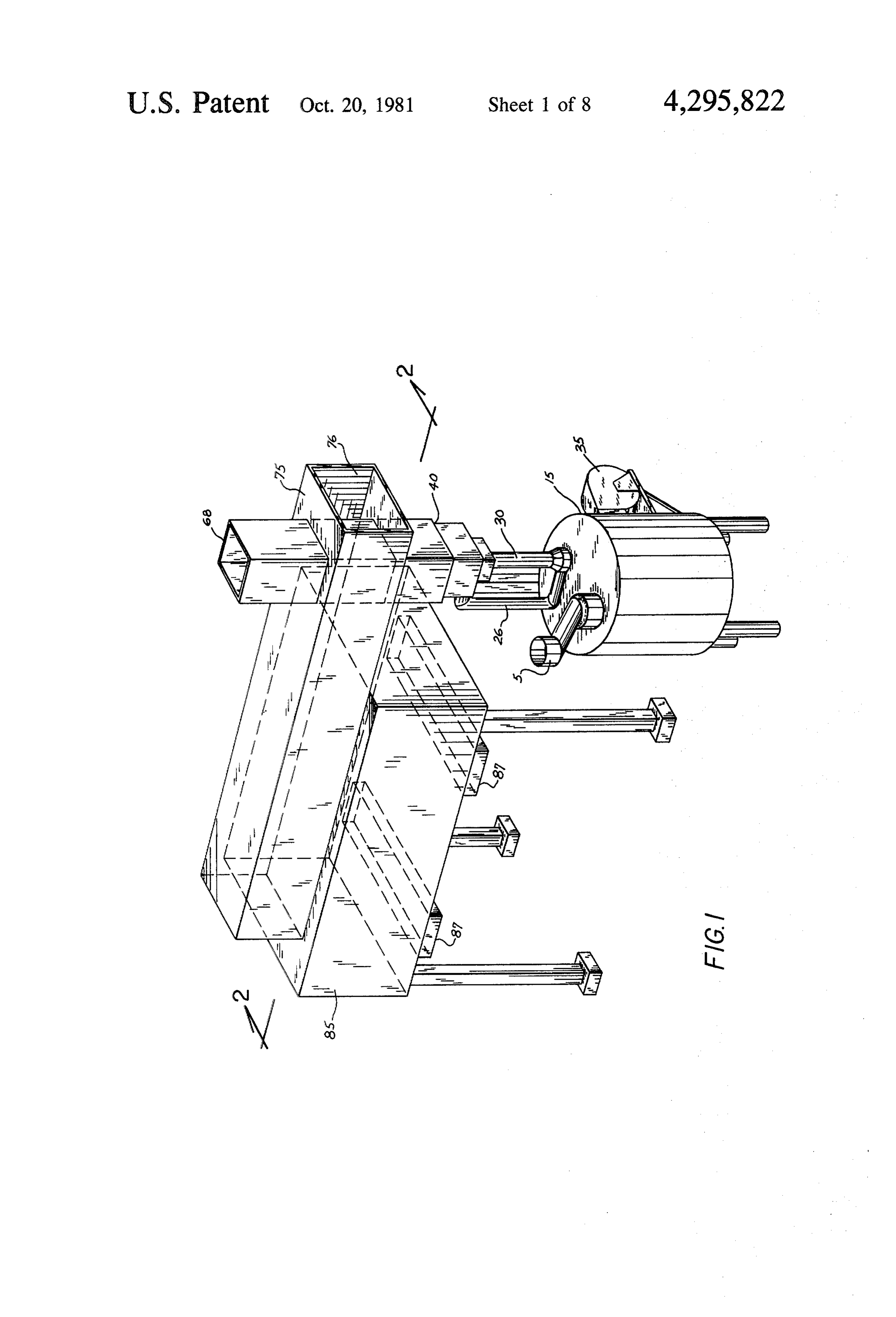
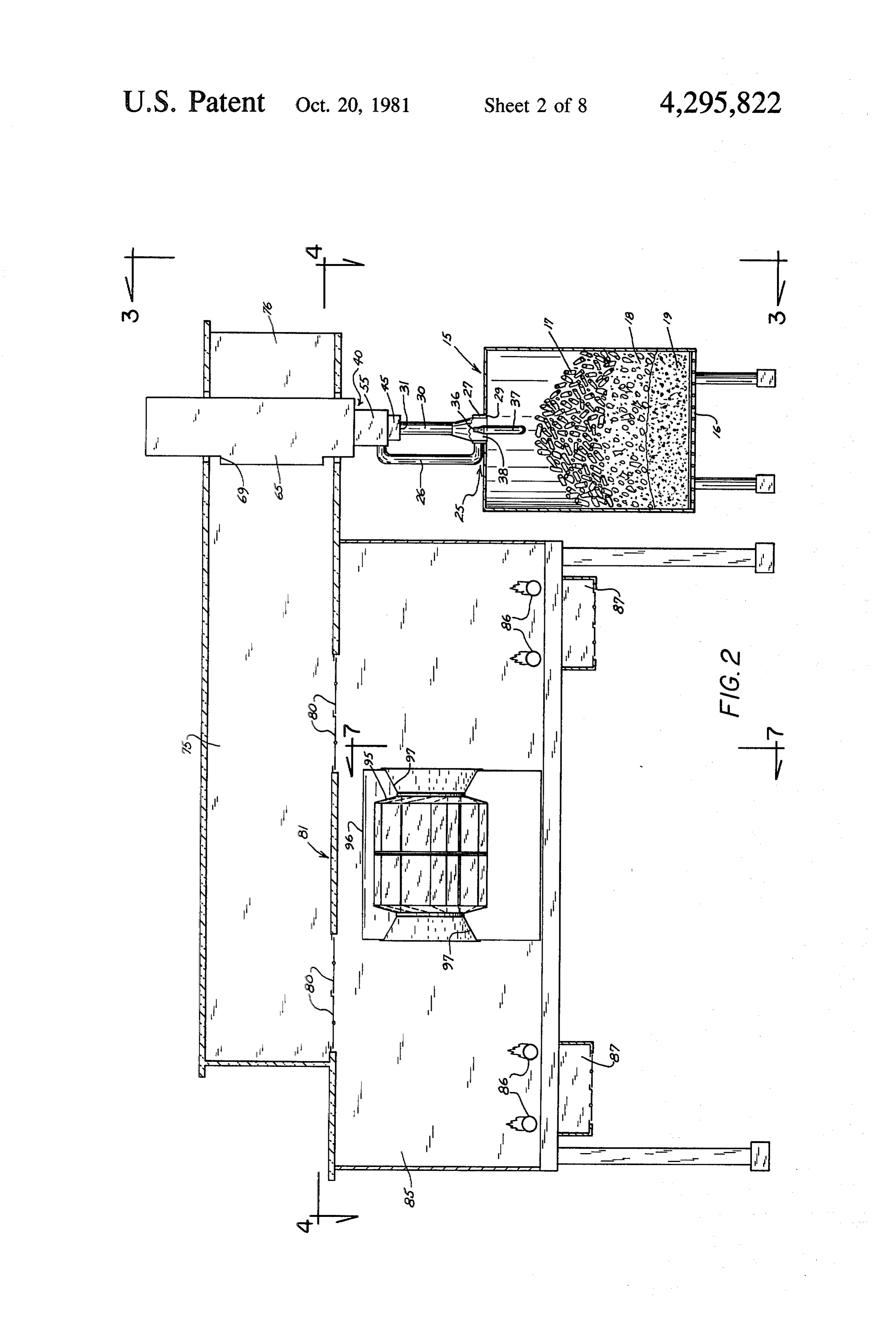
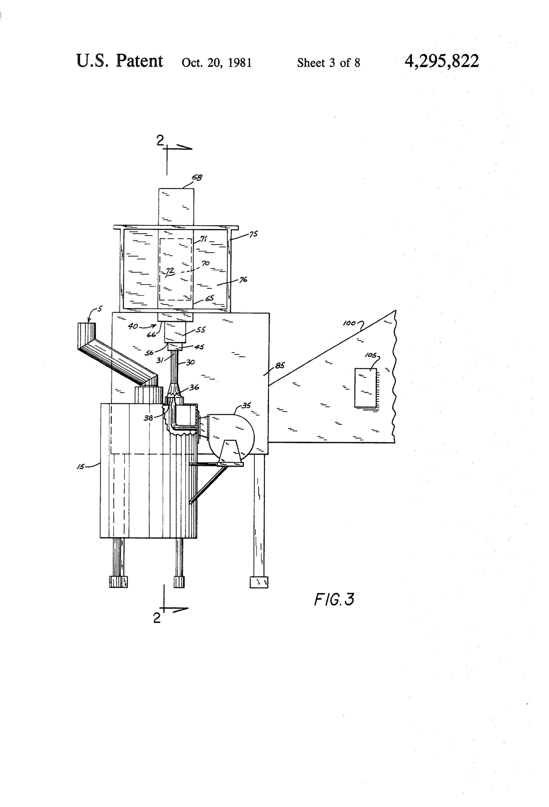
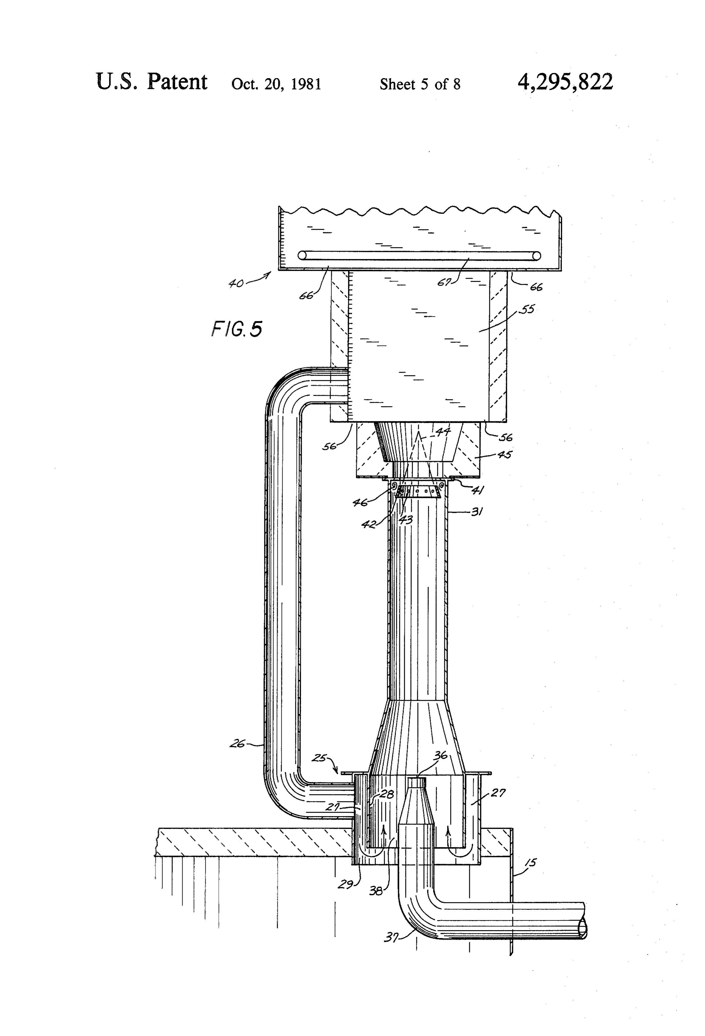
the producer gas lines, or burner throats, which carry the combustible gas from the producer to the burner. BRIEF DESCRIPTION OF THE DRAWINGS The tar would not only impede producer gas flow but 20 FIG. 1 is a perspective view of the present invention, would also collect upon fan means typically placed FIG, 2 is a front elevational, cross-sectional view in-line in the throat to draw the producer gases into the taken along line 2-2 in FIG. 1. burner from the producer. The residue, or tar, accumu FIG. 3 is an end elevational view taken along line lation has been the result of the condensation, within the 3-3 in FIG. 2.
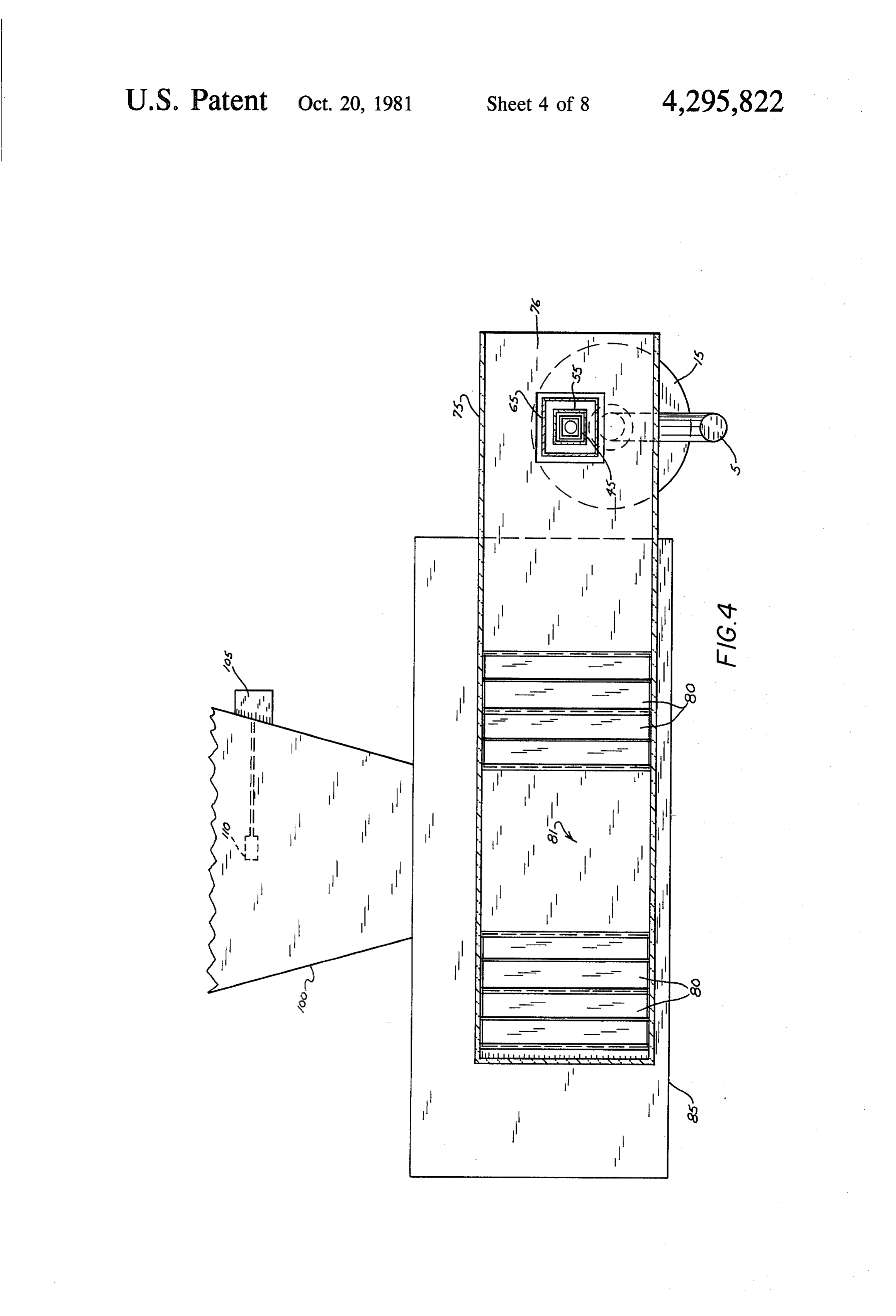
burner throat, of distillates which flow with the pro 25 FIG. 4 is a plan view taken along line 4-4 of FIG. 2. ducer gases out of the producer. FIG. 5 is an elevational, cross-sectional view of the SUMMARY OF THE INVENTION burner throat of the present invention secured between The present invention overcomes the problems of the the producer and the burner,
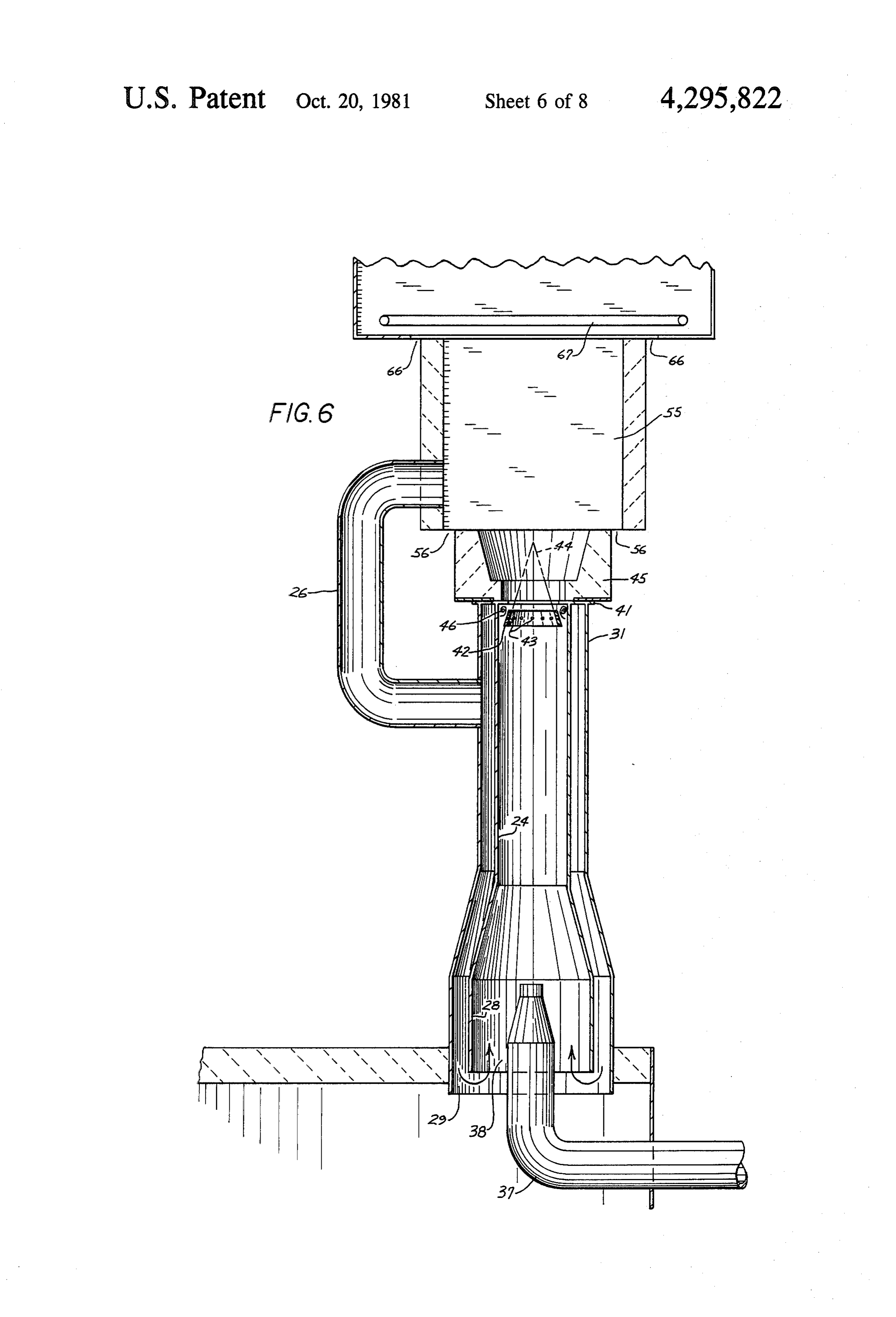
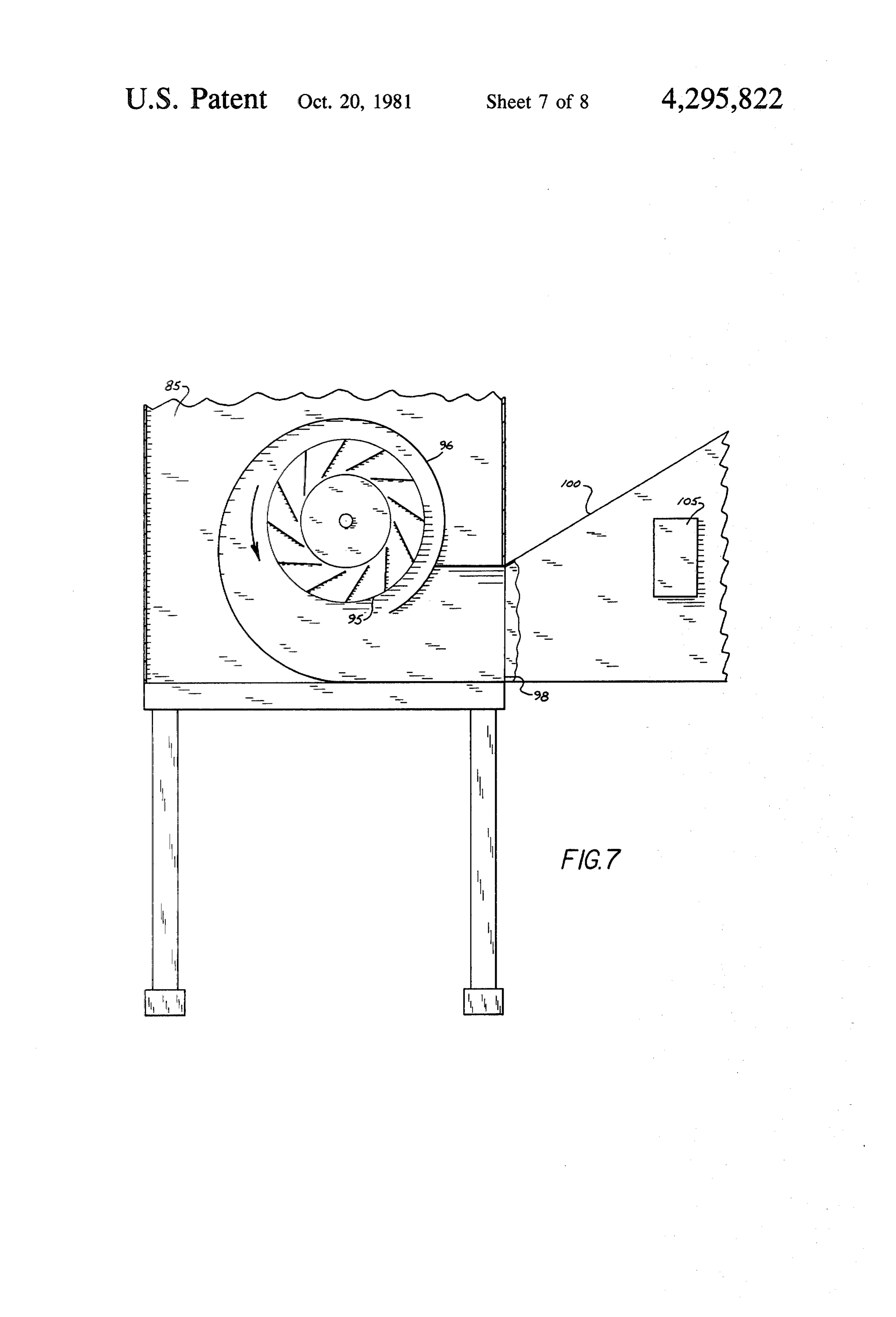
FIG. 6 is an elevational cross-sectional view of an prior art, described above, by providing a superheating 30 alternate embodiment of a hot jacket portion of the means at the inlet to the burner throat so that distillates flowing with the producer gases out of the producer are burner throat of the present invention. FIG. 7 is a cross-sectional, elevational side view superheated sufficiently above their condensation tem taken along line 7-7 of FIG, 2.
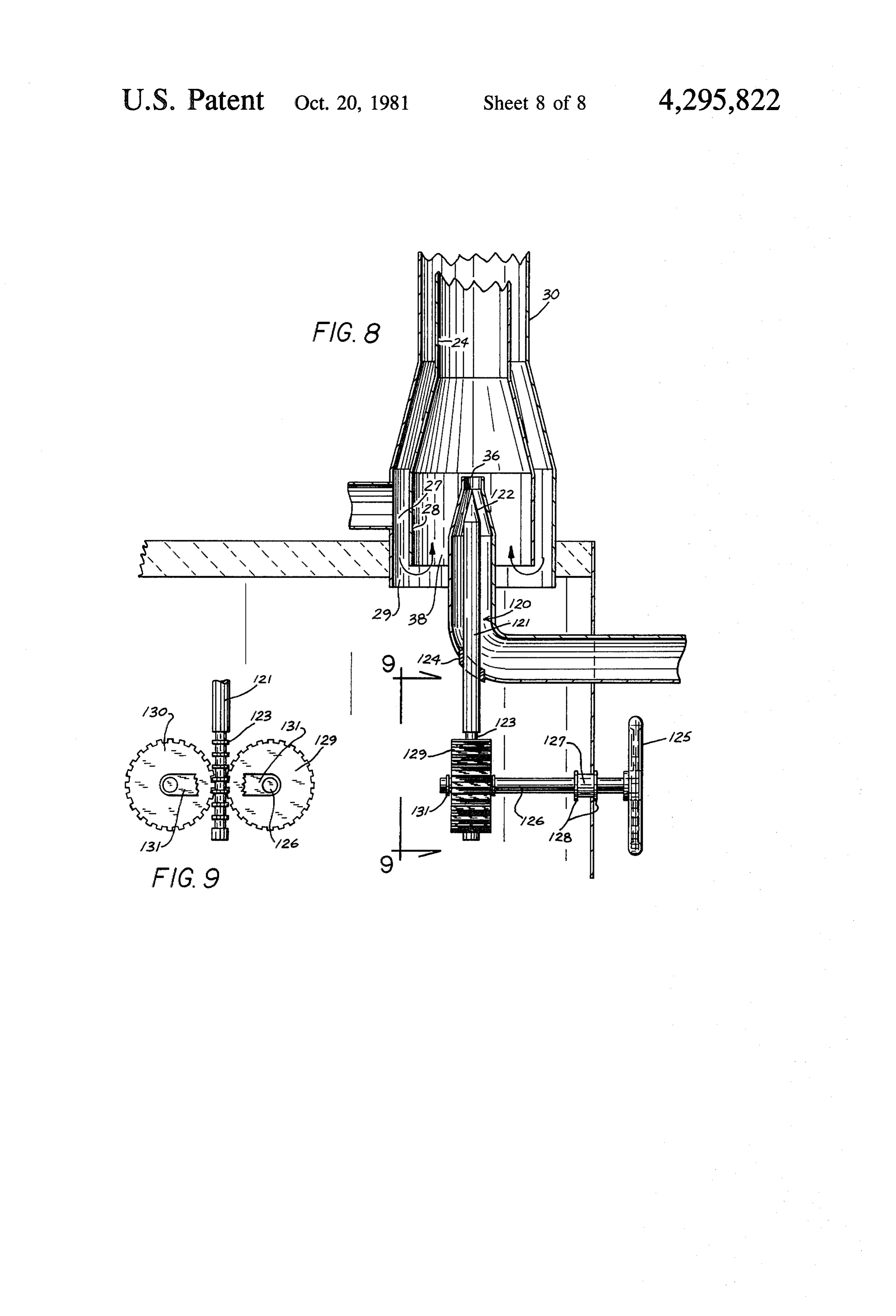
peratures to limit condensation within the burner throat FIG. 8 is an elevational cross-sectional view of an to acceptable levels. Additionally, an out-of-line fan 35 alternate embodiment of the out-of-line fan showing a means is provided to create suction within the burner needle valve adjustment means for the airstream jet. throat, by means of a jet airstream, without exposing the FIG. 9 is an elevational side view taken along line fan to any condensate formation within the throat. The 9-9 in FIG. 8 showing the adjustment mechanism of superheating means employed is the recirculation of hot the needle valve.
combusted gases from the burner. The out-of-line fan DESCRIPTION OF THE PREFERRED has the dual function of providing primary combustion EMBODIMENT oxygen to the superheated producer/gas distillate flow in the throat so that a superheated combustible mixture The present invention is a system and apparatus for is delivered to the burner. The burner is multichan 45 drying seed corn using organic materials such as corn bered with an ignition chamber providing for initial cobs and other by-products of the seed corn production combustion, a combustion chamber providing for pri process as fuel. The system includes a novel producer mary combustion, and a furnace chamber allowing for gas burner system designed to inhibit residue formation any final combustion and including the provision of a which has been a problem in this field. heated exterior surface to transmit heat to a fluid flow. 50 As a brief overview, with reference to FIGS. 1-3, The burner includes secondary air supplies to permit corn cobs are loaded through a feeder 5 into the pro complete combustion of the producer gases in an excess ducer 15 where they are burned to produce a combusti of oxygen. The heated exterior surface of the furnace is ble producer gas. The gas is utilized in a novel producer enclosed within a tunnel to heat a fluid flow which is gas burner system 40 which has been designed to inhibit drawn through the tunnel and into a large fan enclosed 55 the formation and accumulation of condensates. The within a fan room. The fan room includes a supplemen producer gas fuels the burner system to generate heat. tal heat source and a plenum receives a heated dis The heat is transferred to an air flow which is drawn charge air flow from the fan to distribute to grain bins. through air tunnel 75 by a fan 95, housed in the fan The discharge air flow is monitored, with a temperature room 85. The heated air is routed by fan 95 through control means simultaneously varying the rates of heat 60 plenum 100 to bins to dry seed corn, or to some other generation from the burner and the supplemental heat drying application.
source, and the positions of fluid control dampers to While the instant application of the heat generated by achieve a desired temperature for the heated discharge the present burner system is to dry seed corn; it should fluid flow in the plenum. be understood that the described drying application is It is therefore an object of the present invention to 65 merely representative and that the heat generated by provide a burner system for organically generated pro the burner system could obviously be applied to various ducer gases which limits residue accumulation to an other uses such as to power an electric generator, for acceptable degree. example.
Page 11scan →
In the description which follows, the producer 15 directed vertically upward in the inlet portion of burner will be described only in limited detail inasmuch as gas throat 30, and creates a suction force in suction chamber producers are well-known in the art. It is, moreover, 38 of throat 30 which is directly proportional to the intended to be understood that producers burning or velocity of the air stream. That is, the greater the veloc ganic materials other than corn cobs to yield producer 5 ity of the air stream, the lower the pressure in chamber gases could be utilized to accomplish the purposes of 38, and thus, the greater the suction force drawing in this invention, and thus, that the invention is not in the producer gas/distillate flow. The fan 35 includes an tended to be limited to the producer briefly described inlet butterfly valve (not shown) which can be adjusted herein. In particular, refuse grains, fungicide treated to regulate the air intake and therefore, the velocity of corn, and husk materials from shelling would be suitable 10 the air jet. The butterfly valve, thus, regulates the suc organic fuels for use with the present invention. tion force in the burner throat 30. (This butterfly valve Now, more particularly, with reference to FIG. 1-3, is tied in with an overall temperature control mecha once the cobs have been loaded through the feeder 5 nism which will be described later.) Inasmuch as the fan into producer 15, and the invention is operating nor 35 is taken outside of the producer gas/distillate flow, it mally, the fuel bed within the producer 15, may be 15 is kept free of any residues which condense within the considered to consist of three zones: The uppermost throat 30.
Zone is the distillation zone 17, the intermediate zone is The air stream, in addition to motivating the gas flow, the reduction zone 18, and the lowermost zone is the serves the dual function of providing the primary air oxidation zone 19. The cobs travel down through these supply for combustion.
zones being successively reduced in each Zone so that 20 In fact the air stream introduced jet 36 comprises a they leave the bottom 16 of producer 15 as ashes. A primary combustion oxygen airstream inasmuch as it is waste disposal means, typically of a conveyor type, is designed to supply sufficient oxygen to permit complete normally provided under the producer to dispose of the combustion of the gas generated by the producer. To ashes. The oxidation zone 19 is comprised of hot coals appreciate this feature, recall that the velocity of the jet and includes an air flow introduced through the bottom 25 stream determines the amount of suction force in suc 16. In the reduction zone 18 the cobs are in a charcoal tion chamber 38. The suction force in chamber 38, in form, and in this zone 18 the producer gases, primarily turn, determines the amount of air drawn in through the carbon monoxide and hydrogen, are formed. These bottom 16 of the producer 15 for combustion of the producer gases flow upward through the distillation cobs. Note, that cob loader 5 is air sealed. Therefore zone 17 due to a suction in the burner throat 30 (later 30 given the suction force in suction chamber 38, the bot described). In flowing through zone 17, the hot gases tom 16 provides the air inlet for the upward fluid flow rise through the cobs, carrying along amounts of water through the producer. The velocity of the jet air stream, and hydrocarbons which are distilled from the cobs. therefore, determines the amount of oxygen available These distillates flow with the producer gases to com for cob combustion, and hence, the rate of production prise a producer gas/distillate flow to burner 40 35 of producer gases. Given this direct relationship, one through burner throat 30. Note that the producer is skilled in the art can determine the amount of oxygen under a negative pressure so that harmful, or undesirea supplied through jet 36, or the rate of air mass flow, ble gases can't leak into the atmosphere. which is necessary to permit complete combustion of In the past, the problem has been that a substantial gas generated in a producer of given configuration. It portion of the distillates have condensed out of the gas 40 can, accordingly, be appreciated that the present inven mixture while traveling through the burner throat 30, tion is designed to provide sufficient oxygen via jet 36 resulting in the formation of gummy residues, or tar, in to permit complete combustion of the producer gases the throat 30. In time, the residues would accumulate to generated at any given jet stream velocity. Observe that the point where the flow through the throat 30 was the mixture of the primary combustion oxygen air substantially restricted. In addition, it has been custom- 45 stream with the producer gas/distillate flow in suction ary in the prior art structures to employ an in-line fan chamber 38 produces a combustible mixture which will means in the burner throat to draw the producer gas out burn at combustion temperature. It is also noted that the of the producer 15. The residues would accumulate on butterfly valve of the out-of-line fan 35, by determining the fan rendering it effectively inoperable unless regu the air stream velocity and rate of producer gas genera larly cleaned. 50 tion, thereby comprises a heat generation adjustment The present invention discloses a structure which means for the burner 40.
was invented to eliminate this residue problem. FIG. 8 shows an alternate embodiment of the out-of The structure comprises a burner system which in line fan which includes a means for adjusting jet 36. A cludes a novel burner throat design 30 which mixes a needle valve 120 which is adjustable vertically to vary primary air supply with the combustible gas mixture to 55 the flow from jet 36. While various adjustment mecha provide for combustion in the three chambered burner nisms could be utilized, here a notched end 123 of shaft 40. The throat structure 30 in addition to mixing pri 126 is sandwiched between notched wheels 130 and 129 mary combustion air, later described in detail, has been connected by link 131. Idler wheel 130 is rotationally specifically designed to inhibit condensate formation, secured to a shaft (not shown) which is rigidly secured and thereby, solve the residue problem described above. 60 to producer 15; while driving wheel 129 is rigidly se This burner throat structure comprises the combina cured to a shaft 126 which is rotationally secured to tion of an out-of-line fan 35 with a super heating means producer 15 by means of spacer discs 128 and bearing 25. seal 127. The hand wheel 125 can, thus, be operated to With particular reference to FIGS. 3 and 5, the out move the shaft 121 vertically with respect to bearing of-line fan 35 draws in outside air at ambient tempera- 65 seal 124, and adjust the position of pointed end 126 ture through an ambient air inlet (not shown) and expels relative to jet 36. The valve 120, therefore, is adjustable it in a high velocity air stream through jet 36 disposed at to vary the velocity of the air stream, and the rate of our the discharge end of nozzle 37. The air nozzle 37 is mass flow expelled from jet 36.
Page 12scan →
In combination with the out-of-line fan 35, a super Moreover, where condensate conditions are more se heating means 25 is employed to inhibit condensation. vere, the hot jacket can be extended upwards to encir The superheater 25 superheats the producer gas/distill cle the entire length of throat 30, or, at least, an interme late flow, or combustible mixture, in the suction cham diate portion thereof. See FIG. 6. Here, hot return gas ber 38 to a superheated temperature so that the distil line 26 is relocated upwardly, so that the hot combusted lates are held above their condensation temperature. By gases must flow down the entire length of throat 30 maintaining the distillates above their condensation before being drawn into suction chamber 38. In this temperature while they travel through the producer gas alternate embodiment, condensate is unable to form on line, they remain gaseous and do not convert to the the interior walls 24 of throat 30 due to their heated liquid residue form. 10 state, and consequently, any liquid condensate particles In that the distillates were distilled from the cobs at would remain in the fluid flow and travel into burner the temperature of the gases in the producer, or the 40. In either embodiment, therefore, the hot combusted producer temperature, they will begin to condense at gases both superheat the producer gas/distillate flow temperatures at and below that producer temperature. and provide for a hot jacket to inhibit condensate for Therefore, to prevent condensation within the throat 15 mation.
30, the distillates must be maintained at a superheated Thus, the intake structure of the present invention temperature in excess of the producer temperature reduces the residue problem by superheating the pro while flowing to the burner 40. ducer gas/distillate flow while providing a suction While various means could be utilized to superheat force in the throat 30 without exposing the fan means to the producer gas/distillate flow, in the preferred em 20 any condensate which may form. This later feature bodiment, hot combusted gases are recirculated from minimizes the maintenance effort required to keep the the burner and introduced into suction chamber 38. fan operational.
FIGS. 2 and 5 show the return gas line 26 rerouting hot With the burner throat 30, thus, designed to permit combusted gases from the combustion chamber 55 of substantially unimpaired flow, the superheated combus the burner 40 (later described) to an annular collar 27 25 tible mixture is introduced into the burner 40 through which encircles suction chamber 38. The hot gas travels the outlet portion 31 of throat 30. down the collar 27 and out through open end 29 where The burner 40 is a multichambered burner comprised it mixes with and superheats the producer gas/distillate of three chambers, or combustion zones. Briefly: The flow draw into the suction chamber 38. first is the ignition chamber 45 which initially provides The applicant has found that the hot combusted gas 30 combustion temperature for the superheated combusti from burner 40 is generally at a temperature signifi ble mixture provided by burner throat 30. The second is cantly hotter than the producer temperature. Super the combustion chamber 55 wherein the principal com heating by means of these gases has, thus, been found to bustion ensues. The third combustion zone comprises eliminate, or at least, substantially inhibit condensation. the furnace chamber where complete and final combus The suction necessary to draw the hot gases down 35 tion of any remaining combustible gas ensues in an ex return line 26 is provided by the fluid communication cess of oxygen.
between annular collar 27 and suction chamber 38 via Now, more specifically, just below, the entrance to open end 29. The suction force of chamber 38 draws the ignition chamber 45 a flame retention ring 41 is secured hot gases down line 26 to mix with the upward flowing within the outlet portion 31 of throat 30. (See FIG. 5) producer gas/distillate flow. Inasmuch as the producer 40 The ring 41 includes a flame retention, or igniting, gas/distillate flow is virtually simultaneously being means of a type which is well known in the art. The mixed with the primary combustion oxygen air stream flame retention means comprises an angled flange 42 through jet 36, and superheated by mixture with the hot having apertures 43 spaced intermittently thereabout. cornbusted gases introduced through the annular collar In operation, the flange 42 constricts the incoming su 27, a superheated combustible mixture is produced in 45 perheated combustible mixture so that its velocity is the suction chamber to flow upward through the burner increased and a cone shaped flame boundary 44 is cre throat 30 and into burner 40, ated. The flame doesn't penetrate cone 44 because the It is observed that even though the air introduced by velocity of the flame front is less than the velocity of the fan 35 will become heated somewhat in passing through incoming superheated combustible mixture within the the hot curved nozzle 37 before arriving at jet 35, the air 50 cone 44. The apertures 43 encircling flange 42 leak the stream will cool the producer gas/distillate flow some combustible mixture through the flange where it ignites what, and thereby, cause some condensation of the to create low velocity flame eddys 46. These eddys 46 distillates. Any condensation, however, will be kept at swirl about just below the inlet portion of ignition an acceptable level by the superheating effect of the hot chamber 45 and ignite the incoming superheated com return gas described above. 55 bustible mixture around the base of cone 44. It is also noted that the vertical orientation of throat As has been explained above, combustion of the pro 30 causes any liquid condensate forming on the inside ducer gases in ignition chamber 45 is permitted by the walls to either drip back down into the producer 15, or primary combustion oxygen supplied by the jet air to be drawn upward into burner 40 inasmuch as liquids stream of the out-of-line fan 35. The burner 40 of the can not remain at reast on vertical surfaces, Liquid 60 instant structure, however, in order to ensure complete condensate particles not forming of the walls of throat combustion, provides for secondary air supplies which 30 will remain in the fluid flow and travel into burner ensure that oxygen in excess of that required for com 40, With reference to FIG, 5 it can furthermore be plete combustion is available. The first flow of excess appreciated that annular chamber 27 comprises a hot combustion oxygen is provided through second air inlet jacket encircling suction chamber 38 such that the in 65 means 56 of the combustion chamber 55. Combustion side surface 28 of suction chamber 38 runs quite hot, chamber 55 is the principal combustion chamber, burn The heat of chamber wall 28 prevents condensate from ing the major share of the unburned portion of the com forming thereon, and therefore, the wall 28 runs clean, bustible mixture flowing from the ignition chamber.
Page 13scan →
After combustion in combustion chamber 55, the com regulate the dampers, gas burners and the furnace to bustible mixture comprises a primary hot combusted gas achieve a desired temperature in the heated discharge flow flowing upward into the furnace chamber 65. Re fluid flow. (Note that locating the temperature probe in call that return gas line 26 draws a portion of the hot close proximity to the bins is advisable to ensure a sta combusted gas flow from combustion chamber 55 for ble, reliable reading.) The control mechanism links the recirculation as described above. While complete com butterfly valve of the out-of-line fan, the first dampers, bustion is normally achieved in combustion chamber 55, the gas burners, and the second dampers by several final, and complete, combustion of the producer gases interconnected positioners which operate simulta may occur in the furnace chamber 65. Third air inlet neously.
means 66, positioned at the base of furnace 65, provides O Inasmuch as there are various control systems which for the mixing of a second flow of excess combustion could be designed to operate the temperature control oxygen to complete the combustion of any remaining mechanism hereinafter described, the control system producer gases. Furnace 65 includes a gas ring burner will not be described in detail. Various means well 67 which serves both as a pilot and a smoke control known to one of ordinary skill in the control industry means at cold start up as will later described more fully. 15 are available to function as hereinafter specified. The Furnace 65 comprises a steel chamber having an open term positioners is, thus, intended to represent any suit upper end 68 which functions as a stack, or chimney. able system and could include the use of hydraulic cyl The primary hot combusted gas flow flows upward inders, air cylinders, or electric motors, for example. through the furnace 65, being discharged through stack The temperature control system is capable of operat 68 as a stack discharge flow. The upward flow of the 20 ing in four modes: a start-up mode, a furnace only mode, hot combusted gases through the interior region 70 a gas burners only mode, and a combination mode. An heats its exterior wall 71 so that the exterior surface 72 operator is available to monitor the system, and will of furnace chamber 65 becomes quite hot. Furnace 65 is make all major changes in the system such as switching positioned centrally at the open end 76 of an air tunnel the system from one mode to another. 75 as shown in FIGS. 2 and 3. The tunnel 75 encloses a 25 In the start-up mode, with the first dampers closed, portion of the heated exterior surface 72. During nor cobs are burned in the producer to yield producer gases mal operation, the tunnel 75 includes a fluid flow flow which flow up into the furnace 65 where they are ig ing proximate to enclosed heated surface 72 so that heat nited by the gas ring burner pilot 67. The ring burner is transferred to the fluid flow, the fluid flow compris also serves as a smoke control means until the furnace ing a first heated fluid flow. 30 achieves operating temperature by burning the smoke, As is best seen in FIG. 2, air tunnel 75 is in fluid or oxidizing the otherwise visible carbon particles. With communication with fan room 85 by means of first the furnace and the other two burner chambers de dampers 80 which are located on a common wall 81. scribed above providing for complete combustion of Fan room 85 houses large fan 95, and when the fan 95 is the producer gases, operating temperature is achieved, operating, and the dampers 80 are open, a fluid flow is 35 and the pilot burners are no longer required for smoke drawn down the tunnel 75 and into fan room 85. This control or to sustain the flame, and they are turned off. fluid flow will be drawn in through the open end 76 of With the burner system at operating temperature the the tunnel 75, and circulate about the enclosed heated operator selects the system into the furnace only mode. surface 72 of the furnace 65 where it will absorb heat. The fan will be either manually turned on from a cold The furnace has an opening 69 and the movement of the 40 start, or will have to be selected out of the gas burners fluid flow past the furnace 65 will create a low pressure only mode, later described. In either case, the tempera area at opening 69, drawing a portion of the primary hot ture sensing probe 110 will register the temperature of combusted gas flow out of the furnace through side the heated discharge fluid flow in the plenum 100, and opening 69, this furnace opening discharge flow further if the discharge flow is below the desired temperature, heating first heated fluid flow. This first heated fluid 45 the control system 105 will activate the first damper flow is then drawn into the fan 95 via first dampers 80. positioners to begin to open the dampers 80. All of the Large fan 95 is enclosed by an eccentric housing 96 apparatuses operated by the positioners have open, which includes inlet openings 97. The housing 96 has a closed and various intermediate positions. As the first discharge side 98 with a plenum 100 secured thereto. dampers 80 are opened, the rate of flow of the first See FIG. 7. The first heated fluid flow is drawn into 50 heated fluid flow down tunnel 75 is increased. And as large centrifugal fan 95 through diametrically opposed the first dampers are opened, the positioners will simul inlet openings 97, and expelled from the housing 96, via taneously open the butterfly valve of the out-of-line fan discharge side 98, into plenum 100 as a heated discharge increasing the suction in the throat 30, and thus, the rate fluid flow. The heated discharge fluid flow is routed of producer gas and heat generation in the furnace 65. through plenum 100 to bins (not shown) to dry seed 55 This increased heat is carried off by the increased fluid corn or to some other drying or heating application. flow through the air tunnel 75 caused by the simulta Fan room 85 also includes auxiliary burners 86 and neously opened first dampers 80, described above. second dampers 87. Second dampers 87 can be opened Therefore, by operating the dampers and butterfly to permit the flow of outside ambient air into fan room valve simultaneously the temperature of the heated 85. Auxiliary burners 86 are employed as a supplemen 60 discharged fluid flow is quickly increased. It is observed tal heat source and are utilized when the heat obtained that while the positioners are opening the furnace from the furnace 65 is insufficient in a manner later dampers and the butterfly valve, they are simulta described. While various conventional burners would neously opening the throttle valves of gas burners 86, be suitable, in the preferred embodiment, gas burners and closing the second dampers 87; although dampers are utilized as auxiliary burners 86. 65 87 are never fully closed. In the furnace only mode, A temperature control mechanism 105, including a however, the gas burner pilots are not activated, and temperature sensing probe 110 disposed in plenum 100, the gas supply line valve is closed. Consequently, the is positioned subsequent the discharge side of fan 95 to gas burners are supplying no supplemental heat in the 14 furnace only mode even though their throttle valves materials, said producer gas flow including distillates have been opened. which distill out of said organic materials and compris If the desired temperature is not achieved with the ing a producer gas/distillate flow, said distillates have a first dampers and the out-of-line fan butterfly valve in condensation temperature, comprising: their fully open positions, the control system may be a burner means for combustion of said combustible Selected by the operator into the combination mode. producer gases externally disposed with respect to (Note that various instruments would be available to the said gas producer; and operator including a plenum temperature gage from a burner throat means for providing fluid communi which he can determine what actions are necessary to cation with and disposed between said producer achieve the desired temperature.) In selecting the sys O and said burner means, said burner throat means tem into the combination mode the operator will acti carrying said producer gas/distillate flow from said vate the gas burner pilots. With the pilots activated, the producer to said burner means, said burner throat on/off supply valve can be manually opened to supply means including a superheating means for super gas to the burners 86. The throttle valve at burner 86 is heating said producer gas/distillate flow to a super then operated by a positioner to regulate the flow of gas 15 heated temperature, said superheated temperature to the burners 86, and consequently, the rate of supple being above said condensation temperature, said mental heat generation. Since, at this point, the first superheated producer gas/distillate flow having a dampers and butterfly valve are fully open, and the gas temperature above said condensation temperature burners are, likewise, at full force, with the second while flowing through said burner throat means. dampers nearly closed, the desired discharge air flow 20 2. The apparatus of claim 1 further comprising a fan temperature will be achieved within the design limita means for moving a fluid flow through said burner tions. If the desired temperature is exceeded, the control throat means.
mechanism will activate the positioners to start to close 3. The apparatus of claim 2 wherein said superheating the first dampers, butterfly valve, and gas burner throt means comprises a return gas line, said return gas line tling valves to reduce heat generation; and, simulta 25 providing for fluid communication between said burner neously, the mechanism will open the second dampers means and said burner throat means, a hot combusted to permit cooler outside air to merge with and cool the gas flow moving from said burner means through said flow through the fan. The gas burners together with the return gas line and into said burner throat means, Second dampers, thus, supply a variable temperature air wherein said hot combusted gas flow superheates said flow to fan 95. 30 producer gas/distillate flow.
The control mechanism will remain in this combina 4. The apparatus of claim 3 wherein said burner tion mode, automatically regulating the system to stay throat means has an inlet portion, and said fan means is at the desired temperature. In order to switch back to an out-of-line fan, said out-of-line fan including a nozzle the furnace only mode the gas burner on/off supply and a jet, said nozzle having a discharge end, said jet valve would be manually closed, terminating the gener 35 being disposed at said discharge end and being proxi ation of supplemental heat. mate said inlet portion of said burner throat means, said The system also includes a gas burners only mode out-of-line fan having an ambient air inlet and discharg during which the fan draws heat only from the gas ing an air stream through said jet to move said fluid burners 86. In this mode the second dampers remain in flow through said burner throat means. the fully open position, and the first dampers in the fully 40 5. The apparatus of claim 4 wherein said air stream closed position. from said jet creates a low pressure region in said inlet In closing, the present invention, as can now be un portion of said burner throat means, said inlet portion derstood, comprises a structure which can utilize the comprising a suction chamber, said suction chamber byproducts of grain production to generate heat and being surrounded by an annular collar, said annular dry the grain products. The invention, moreover, has 45 collar having an open lower end, said annular collar great flexibility in application, and can be adjusted to providing for fluid communication between said return accomodate virtually any conceivable number of grain gas line and said suction chamber.
bins. Depending on the drying demand, and the avail 6. The apparatus of claim 5 wherein said burner ability of grain production byproducts such as corn throat means is vertically oriented, said annular collar cobs, the structure can generate the required heat solely 50 having said hot combusted gas flow passing there by means of waste products combustion, or can be used through and comprising a hot jacket surrounding said in combination with conventional burners when neces suction chamber, said suction chamber having an inside sary. surface, said hot jacket transmitting heat to said inside Having, thus, disclosed the present invention it can be surface whereby condensation of said distillates upon appreciated that the invention will indeed function as 55 said inside surface is inhibited. described. It is intended to be understood, however, 7. The apparatus of claim 6 wherein said out-of-line that various changes could be made to the disclosed fan discharges said air stream vertically within said structure which would be only obvious modifications vertically oriented burner throat means, said jet being thereof, and therefore, within the teachings set forth positioned above said open end of said annular collar, herein. Accordingly, within the scope of the appended 60 and wherein said air stream comprises a primary con claims, the invention can be practiced otherwise than as bustion oxygen air stream which mixes with said super specifically described. heated producer gas/distillate flow to comprise a super i claim: heated combustible mixture.
1. In combination with a gas producer, said gas pro 8. The apparatus of claim 7 wherein said burner ducer being suitable for generating a combustible pro 65 throat means has an outlet portion, and wherein said ducer gas from the combustion of organic materials, outlet portion is rigidly secured to said burner means, Said combustible producer gas comprising a producer and said inlet portion is rigidly secured to said gas pro gas flow traveling through a portion of said organic ducer, said burner throat means further including a 15 flame retention ring disposed proximate said outlet por nace opening discharge flow mixing with said first tion, said flame retention ring constricting said super heated fluid flow and thereby increasing the tempera heated combustible mixture as said superheated com ture of said first heated fluid flow.
bustible mixture is discharged from said outlet portion. 12. The apparatus of claim ii said fan room includes 9. The apparatus of claim 8 wherein said burner a gas burner and a second damper, said Second damper means comprises a multichambered burner which in permitting fluid communication between said fan room cludes an ignition chamber, a combustion chamber, and and ambient air outside of said fan room, said gas burner a furnace chamber; said ignition chamber having an comprising a supplemental heat source and being opera inlet portion proximate said outlet portion of said ble with said second damper to provide a variable tem burner throat means, an incoming superheated combus O perature air flow to said large fan. tible mixture being discharged from said burner throat 13. The apparatus of claim 12 wherein said large fan into said ignition chamber, a portion of said incoming is enclosed by an eccentric housing, said eccentric hous superheated combustible mixture being ignited by said ing having an inlet opening and a discharge side, a ple igniting means, and said flame retention ring constrict num chamber being proximate said discharge side and ing said incoming superheated combustible mixture to 15 in fluid communication with said eccentric housing, produce a conical flame barrier, a portion of said incom said large fan drawing in said first heated fluid flow and ing superheated combustible mixture being burned said variable temperature air flow through said inlet within said ignition chamber to comprise an amount of opening, and discharging a heated discharge fluid flow hot combusted gas; said combustion chamber being through said discharge side and into said plenum, a positioned operationally subsequent said ignition cham 20 temperature sensing probe being disposed in said ple ber, an unburned portion of said superheated combusti num chamber, said probe being operationally connected ble mixture flowing from said ignition chamber to said to a means for temperature control wherein said probe combustion chamber, said hot combusted gases also indicates to said temperature control means whether flowing from said ignition chamber to said combustion said heated discharge fluid flow in said plenum has a chamber, said combustion chamber including a second 25 temperature above a desired temperature or below said air inlet means for providing a first flow of excess com desired temperature, said temperature control means bustion oxygen, a large portion of said unburned por being operably connected to plurality of positioning tion of said superheated combustible gas being burned means for adjusting a plurality of adjustable apparatus, in said combustion chamber to comprise a primary hot said adjustable apparatus including said out-of-line fan, combusted gas flow, a portion of said hot combusted 30 said first damper, said gas burner, and said second gas being drawn from said combustion chamber damper, said temperature control means operating said through said return gas line and comprising said hot positioner means to achieve said desired temperature in combusted gas flow; said furnace chamber being posi said heated discharge fluid flow in said plenum. tioned operationally subsequent said combustion cham 14. The apparatus of claim 13 wherein said burner ber, said primary hot combusted gas flow flowing from 35 means has a rate of heat generation and said out-of-line said combustion chamber to said furnace chamber, said fan comprises a heat generation adjustment means for furnace chamber including a third air inlet means for varying said rate of heat generation, said heat genera providing a second flow of excess combustion oxygen, tion adjustment means being variable between an open said furnace chamber having an open upper end, said and a closed position and having a plurality of interme open upper end comprising a stack, said primary hot 40 diate positions intermediate said closed and open posi combusted gas flow being discharged through said tions, said first and said second dampers also having stack and comprising a stack discharge flow. open, closed and intermediate positions, respectively, 10. The apparatus of claim 9 further comprising an air said first and second dampers providing for increasing tunnel, said air tunnel enclosing a portion of said fur fluid communication as said first and second dampers nace chamber, said furnace chamber having an interior 45 are moved from said closed to said open positions, re region and an exterior wall, said exterior wall enclosing spectively, said gas burner including a throttle valve, said interior region and having an exterior surface, said said throttle valve having open, closed and intermediate primary hot combusted gas flow flowing through said positions, said gas burner having a rate of supplemental interior region and transmitting heat to said exterior heat generation, said rate of supplemental heat genera wall wherein said exterior surface of said enclosed por 50 tion increasing as said throttle valve is moved from said tion becomes an enclosed heated surface, said air tunnel closed position to said open position; said positioning having an open end and being in fluid communication means being operably connected to said apparatuses to with a large fan, said air tunnel having a fluid flow from vary said heat generation adjustment means, said first said open end to said large fan, a portion of said fluid and said second damper, and said throttle valve be flow flowing proximate to said enclosed heated surface 55 tween said open and closed positions, respectively; said and absorbing heat therefrom wherein said fluid flow positioning means being operable to simultaneously becomes a first heated fluid flow, said first heated fluid open said heat generation adjustment means, said first flow being drawn into said large fan. damper, and said throttle valve while simultaneously 11. The apparatus of claim 10 wherein said large fan closing said second damper, said second damper being is enclosed within a fan room, and said fan room is in 60 in said closed position when said heat generation adjust fluid communication with said air tunnel by means of a ment means, said first damper and said throttle valve are first damper, and wherein said enclosed heated surface in said open positions, respectively. of said furnace has an opening facing away from said 15. The apparatus of claim 14 wherein when said open end, said fluid flow creating a low pressure area probe indicates to said temperature control means that adjacent said opening whereby a portion of said pri 65 said heated discharge fluid flow has a temperature mary hot combusted gas flow is drawn out of said inte below said desired temperature, said temperature con rior region of said furnace through said opening to trol means will operate said positioning means to simuli comprise a furnace opening discharge flow, said fur taneously move said heat generation adjustment means, 16 said first damper, and said throttle valve towards said a temperature control means for regulating said open positions while said positioning means simulta heated discharge fluid flow to achieve said desired neously move said second damper towards said closed temperature, said temperature control means in position. cluding a temperature sensing probe disposed in 16. The apparatus of claim 15 wherein when said said plenum and operationally connected to said probe, registers a heated discharge fluid flow tempera temperature control means to indicate to said tem ture above said desired temperature, said temperature perature control means whether said heated dis control means will simultaneously close said heat gener charge fluid flow has a temperature below said ation adjustment means, said first damper and said 10 desired temperature or above said desired tempera throttle valve while said positioners simultaneously ture.
open said second damper. 22. The apparatus of claim 21 wherein said large fan 17. The apparatus of claim 16 wherein said heat gen is enclosed within a fan room, and wherein said air eration adjustment means comprises a butterfly valve tunnel includes a first damper, said first damper provid included within said out-of-line fan, said butterfly valve 15 ing for fluid communication between said air tunnel and said fan room, said first heated fluid flow flowing from having a open, a closed and a plurality of intermediate said positions, and wherein said air stream discharged from largeairfantunnel through said first damper and into said within said fan room.
said jet has a discharge velocity, said discharge velocity 23. The apparatus of claim 22 wherein said first increasing as said butterfly valve is moved from said damper closed to said open position, said rate of heat generation 20 pluralityhas of an open position, a closed position and a intermediate positions intermediate said increasing directly with said discharge velocity.
18. The apparatus of claim 7 wherein said primary ting increasingclosed open and said positions, said first damper permit combustion oxygen air stream discharged from said jet is moved from said closedmovement fluid flow position as said first damper to said open posi has a rate of air mass flow, and said out-of-line fan in tions; said burner throat means including a heat genera cludes a butterfly valve to vary said rate of air mass 5 tion adjustment means, and said burner means having a flow, said producer having a corresponding rate of rate of heat generation, said heat generation adjustment producer gas production, said corresponding rate of means having an open, a closed and a plurality of inter producer gas production increasing directly with said mediate positions, said rate of heat generation increas rate of air mass flow wherein said primary combustion ing as said heat generation adjustment means is moved oxygen air stream provides sufficient oxygen for com 30 from said closed to said open positions; said temperature plete combustion of said producer gas. control means being operably connected to said first 19. The apparatus of claim 6 wherein said hot jacket damper and said heat generation adjustment means; said extends upwards from said suction chamber to enclose temperature control means simultaneously moving said an intermediate portion being positioned above and first damper and said heat generation adjustment means contiguous with said suction chamber. 35 towards said open positions, respectively, when said 20. The apparatus of claim 6 wherein said out-of-line temperature sensing probe indicates to said temperature fan includes a needle valve means for adjusting said jet, control means that said heated discharge fluid flow has said needle valve means including a shaft with a pointed a temperature below said desired temperature; and said end, said pointed end being moveable relative to said jet temperature control means simultaneously moving said to very said air stream. heat generation adjustment means and said first damper 21. In combination with a gas producer, said gas towards said closed positions, respectively, when said producer being suitable for generating producer gas temperature sensing probe indicates to said temperature from organic materials, an apparatus comprising: control means that said heated discharge fluid flow has a burner means for burning said producer gas to gen a temperature above said desired temperature. erate heat; 45 24. The apparatus of claim 23 wherein said fan room a burner throat means for providing fluid flow com includes a supplemental heat source, said supplemental munication from said producer to said burner heat source being operationally connected to said tem means, said producer gases flowing from said pro perature control means, said supplemental heat source ducer through said burner throat means into said being activated by said temperature control means to burner means; 50 supply supplemental heat to said large fan when said a large fan; temperature sensing probe indicates to said temperature an air tunnel operationally disposed subsequent said control means that said heated discharge fluid flow has burner means and antecedent said large fan, said air a temperature below said desired temperature while tunnel having an open end and enclosing a portion said heat generation adjustment means and said first of said burner means, said enclosed portion having 55 damper are in said open positions, respectively. a hot exterior surface and comprising an enclosed 25. The apparatus of claim 24 wherein said supple heated surface, said air tunnel having a fluid flow, mental heat source comprises a gas burner, and wherein said fluid flow traveling proximate said enclosed said fan room includes a second damper; said gas burner heated surface and absorbing heat to comprise a including a throttle valve, and having a rate of supple first heated fluid flow, said first heated fluid flow 60 mental heat generation, said throttle valve having an being drawn into an inlet opening of said large fan; open, a closed, and a plurality of intermediate positions said large fan having a discharge side; intermediate said open and closed positions, said tem a plenum disposed proximate said discharge side of perature control means being operationally connected said large fan, said plenum having fluid communi to said throttle valve to move said throttle valve be cation with a grain bin, said large fan discharging a 65 tween said open and closed positions, said rate of sup heated discharge fluid flow through said discharge plemental heat generation increasing as said throttle side and into said plenum, said heated discharge valve is moved from said closed to said open positions fluid flow having a desired temperature; and respectively; said second damper providing for fluid 17 communication between said fan room ambient air out throat means, wherein said hot combusted gas flow side of said fan room, said second damper having an superheats said producer gas/distillate flow. open, a closed and a plurality of intermediate positions 32. The apparatus of claim 31 wherein said burner intermediate said open and closed positions, said tem throat means has an inlet portion and includes an out-of perature control means being operably connected to line fan, said out-of-line fan including a jet disposed said second damper to move said second damper be proximate said inlet portion and discharging an air tween said open and said closed positions, said second stream from said jet into said burner throat means, said damper permitting increasing fluid flow movement as inlet portion comprising a suction chamber, said suction said second damper is moved from said closed to said chamber being in fluid communication with said return open position; said temperature control means including O gas line; said out-of-line fan thereby creating a suction a plurality of positioning means to simultaneously move force within said burner throat means. said heat generation adjustment means, said throttle 33. The apparatus of claim 32 wherein said air stream valve, said first damper, and said second damper be comprises a primary combustion oxygen airstream, said tween said open and said closed positions, respectively, primary combustion oxygen airstream mixing with said said heat generation adjustment means, said first 15 superheated producer gas/distillate flow to comprise a damper, and said throttle valve being in said open posi superheated combustible mixture, said superheated tion when said second damper is in said closed position; combustible mixture being burned in said burner means said temperature control means operating said position to generate heat and comprise said primary hot com ing means to simultaneously move said heat generation busted gas flow.
adjustment means, said first damper, and said throttle 20 34. A method of drying grain, comprising the steps valve towards said open positions respectively, and said of:
second damper towards said closed position when said a. burning organic materials in a producer to generate temperature sensing probe indicates to said temperature a producer gas/distillate flow; control means that said heated discharge fluid flow has b. drawing said producer gas/distillate flow through a temperature below said desired temperature. 25 a burner throat means having a superheating means 26. The apparatus of claim 25 wherein said gas burner for heating said producer gas/distillate flow to a and said second damper supply a variable temperature temperature above a condensation temperature, air flow to said large fan. and delivering said superheated producer gas/dis 27. The apparatus of claim 26 wherein said fan is tillate flow to a burner means at a temperature enclosed by an eccentric housing. 30 above said condensation temperature; 28. The apparatus of claim 27 wherein said burner c. burning said superheated producer gas/distillate means has an open upper end, an interior region, and a flow in said burner means to generate heat; primary hot combusted gas flow flowing upward in said d. transmitting heat generated by said burner means burner means and being discharged through said open to a fluid flow to produce a first heated fluid flow; upper end as a stack discharge flow, said enclosed 35 e. drawing said first heated fluid flow through a large heated surface of said burner means including an open fan and discharging a heated discharge fluid flow ing, said opening facing away from said open end of said from said large fan into a plenum for distribution to air tunnel, said fluid flow through said air tunnel draw one or more grain bins.
ing a portion of said primary hot combusted gas flow 35. The method of claim 34 further comprising the out of said interior region and through said opening to steps of:
comprise a furnace opening discharge flow, said fur a. Sensing the temperature of said heated discharge nace opening discharge flow mixing with said first fluid flow in said plenum; heated fluid flow whereby the temperature of said first b. Indicating to a temperature control means whether heated fluid flow is increased. said heated discharge fluid flow has a temperature 29. The apparatus of claim 28 wherein said burner 45 above a desired temperature or below said desired means comprises a multichambered burner, said multi temperature;
chambered burner including an air inlet means for pro c. Simultaneously adjusting a rate of heat generation viding excess combustion oxygen, and a pilot means for of said burner means and a corresponding rate of providing a combustion temperature. first heated air flow into said large fan by means of 30. The apparatus of claim 29 wherein said producer 50 one or more positioning means operably connected gas generated in said producer flows upward in said to said temperature control means to achieve said producer through said organic materials and includes desired temperature in said heated discharge fluid distillates which distill out of said organic materials to flow in said plenum.
comprise a producer gas/distillate flow flowing into 36. The method of claim 35 further comprising the said burner throat means, said distillates having a con 55 steps of:
densation temperature; and wherein said burner throat operating said positioners to simultaneously increase means includes a superheating means for superheating or decrease a rate of supplemental heat generation said producer gas/distillate flow to a superheated tem from a supplemental heat source, as said rate of perature above said condensation temperature, said heat generation of said burner means and said cor superheated producer gas/distillate flow holding a tem 60 responding rate of first heated air flow are simulta perature above said condensation temperature while neously increased or decreased, respectively, to traveling through said burner throat means. produce said desired temperature for said heated 31. The apparatus of claim 30 wherein said superheat discharge fluid flow in said plenum. ing means comprises a return gas line, said return gas 37. The method of claim 36 wherein said supplemen line providing for fluid communication between said 65 tal heat source is not activated by said temperature burner means and said burner throat means, a hot com control means to produce supplemental heat unless said busted gas flow being drawn from said burner means heated discharge fluid flow in said plenum has a temper through said hot return gas line and into said burner ature below said desired temperature when said rate of 18 heat generation burner means is at a maximum rate, and increased, a rate of variable temperature fluid flow into said corresponding rate of first heated air flow into said said fan is simultaneously decreased; and conversely, as fan is simultaneously at a maximum rate. said rate of heat generation of said burner means, said 38. The method of claim 37 further comprising the corresponding rate of heated air flow, and said second step of providing a variable temperature fluid flow to 5 rate of heat generation from said supplemental heat said large fan by means of said positioners such that as source are simultaneously decreased, said rate of vari said rate of heat generation of said burner means, said able temperature fluid flow into said fan is simulta corresponding rate of first heated fluid flow into said large fan, and said rate of suplemental heat generation neously increased. k k k from said supplemental heat source are simultaneously 10
Provenance
- Collection
- Patents citing this work
- Pages
- 18
- Method
- pdftotext (the PDF's own text layer) + pdftoppm 300dpi page scans
- Patent office record
- patents.google.com →
- Source
- Google Patents citing-documents table
- Assignee
- Campbell Crom B
- Published
- 1981-10-20
- Transcribed from
- patentimages.storage.googleapis.com →