

patent · US4300537A
Solar panel mount
17 November 1981
Text
Page 1bibliographic recordscan →
United States Patent (19)
Davis.
54). SOLARPANEL MOUNT
76), - Inventor: Thomas A. Davis, 1657 Gotham St., Chula Vista, Calif. 92010
51. Int. Cl. ................................................. F24J 3/02 52 U.S. C. .................................... 126/437; 126/424;
3,934,573 1/1976 Dandini............................... 126/443 4,010,614 3/1977 Arthur ................................ 126/425
4,136,674 1/1979 Korr .................................... 126/443 4,187,831 2/1980 Eubank ............................... 126/435 Primary Examiner-James C. Yeung
Attorney, Agent, or Firm-Brown & Martin
A solar collector mounting system includes a vertically extending pedestal for supporting a solar collector at a predetermined minimum height above ground level to provide an unobstructed utilization of the space imme diately surrounding the pedestal. The pedestal includes a pivoting bracket at the upper end for supporting an array of panels for orientation into the sun, and is formed of a hollow structure to define a liquid storage reservoir for storing a heated liquid.
5 Claims, 4 Drawing Figures
Drawings
Page 2drawing sheetscan →
Page 3scan →
curely mounted in the ground or to suitable base struc
SOLARPANEL MOUNT ture in ground and the solar collector array is mounted on the upper end thereof and oriented into the predomi
BACKGROUND OF THE INVENTION nant direction of the sun. . . The array of panels can extend or be sufficiently
The present invention relates to solar energy and above the surrounding terrain at a height h of from 8 to pertains particularly to a mounting for solar collector panels. . . . , ... . . . . 18 feet, such that the array can be mounted in parks and . . The use of flat plate solar collectors has been increas the like without interfering with the usual utilization ing at a fairly rapid rate in recent years. This increase in O thereof. The typical length or height of the column the use of solar collectors is primarily due to the in should be around 11 or 12 feet. Such structures, for crease in cost and the scarcity of formerly cheap and example, can provide shading or other roof-like struc abundant fossil fuels. . . v. . . . tures over park benches, picnic tables, and the like. A One drawback to the use of solar collectors is that a number of the units can be, for example, located and minimum area of exposure is needed for the collection arranged throughout a public park or the like and inter of usable amounts of solar energy. Typically, solar col 15 connected for the supplying of heated water to public lectors are mounted on rooftops of buildings and the buildings and the like.
like, and in vacant land areas on racks or the like. Many The units can also be mounted along streets and thor proposals have been made to build or construct solar oughfares such as boulevards or the like, and intercon collection farms in desert areas and the like, where the 20 neced to provide heated water to nearby homes and land is not normally otherwise useful. other buildings. The height of the lower edge of the The present invention is directed toward a structure solar collector array above the ground surface can be that permits the mounting of usable quantities of solar adjusted to be suitable or compatable with a surround collectors in park areas and in areas surrounding build ing structures without obstructing and permitting the 25 ingItarea.
is contemplated that this structure can support an normal utilization of the ground area. - array of from 4 to 6 fairly large, flat plate panels. These SUMMARY AND OBJECTS OF THE panels can be, for example, on the order of approxi INVENTION . mately 4X8 feet each and an array extending approxi
It is primary the object of the present invention to pro mately 12X 16 feet in area. In mounting the panels as illustrated with the center panels essentially flat and the vide an improved solar collector mounting structure. 30 in accordance with the primary aspect of the present reflectors 18sloping side panels as illustrated in FIG. 1, a pair of side invention a solar collector mounting assembly includes the sun's rays onto may and 20 be desirable in order to reflect a vertically extending column anchored at its lower end exposed to the sun atthe panel which is least directly the particular time. For example, in the ground or to suitable structure on the ground and the illustrated arrangement having a bracket at the upper end for tiltably supporting 35 panels that reflect sun ontoincludes mirrors or reflector the panels on the opposite a solar collector. Another aspect of the invention in side of the array from the sun for optimum early morn cludes the construction of the column to define a stor age reservoir for heated liquid circulated through the ing and late afternoon exposure of these panels. solar collection panels. Turning to FIG. 2, the pedestal 14 anchors or is se cured at the lower end into the ground or base support
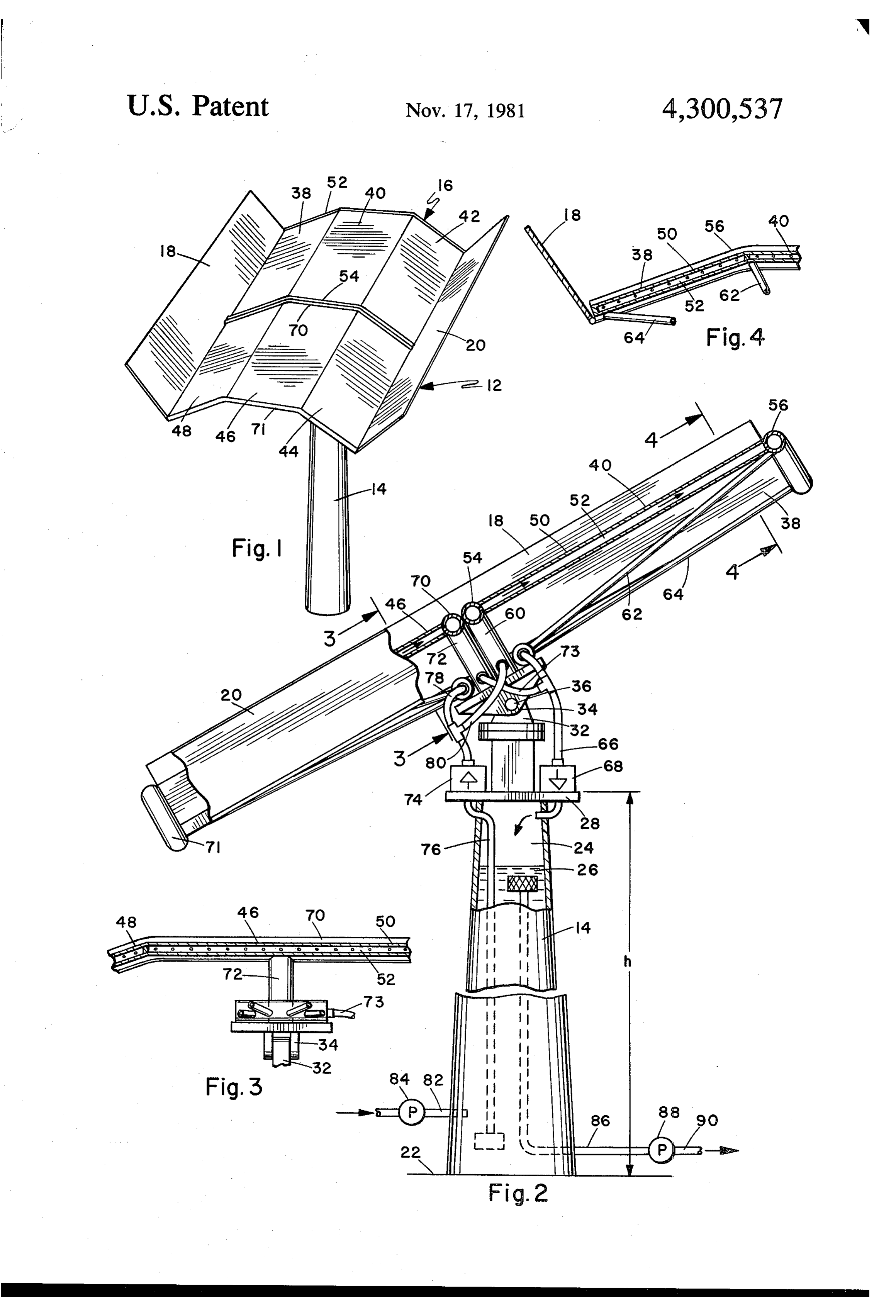
BRIEF DESCRIPTION OF THE DRAWINGS structure 22 in a suitable manner. The pedestal com The above and other objects and advantages of the prises basically an elongated, vertically extending, hol invention will become apparent from the following low or tubular column defining a storage reservoir or description when read in conjunction with the draw chamber 24 in which a liquid 26 such as water or other ings, wherein: 45 suitable liquid is stored. A reasonable size column or FIG. 1 is a perspective view of the solar panel and pedestal can store on the order of about 145 cubic feet mounting pedestal. or 1085 gallons of water. The column 14 includes a FIG. 2 is an enlarged side elevation view of the struc platform or the like 28 at the upper end on which is ture with portions cut away. mounted a bracket including a base member 30 and a FIG. 3 is a sectional view taken on line 3-3 of FIG. 50 swivel or rotatable member 32 which is mounted for 2. rotation about a vertical axis on the member 30. This FIG. 4 is a sectional view taken on line 4-4 of FIG. permits the array of panels to be selectively oriented to 2. the optimum direction of the sun. In addition, proper slewing drive means may be provided for tracking the
Detailed description of a preferred 55 s1
EMBODIMENT The bracket includes an upper pivot member 34 Turning to FIG. 1 of the drawings there is illustrated which is pivoted by means of a pin 36 to the member 32 an array of discrete solar collection panels mounted on for permitting the array of panels to pivot about a hori the upper end of a pedestal. In the illustrated embodi 60 zontal axis.
ment the combination designated generally by the nu The array 16 as illustrated in FIG. 1, of solar collec meral 12 includes a vertically extending, cylindrical tors consists of a plurality of discrete flat plate collector pedestal 4 having an array of panels 16 mounted on the panels 38, 40, 42, 44, 46 and 48 mounted in a suitable upper end thereof. The pedestal can take any suitable framework in support structure not specifically dis form such as circular, square, or the like, and preferably closed and interconnected for providing a flow of fluid has a height sufficient to position the solar collector 65 to be heated therethrough.
array 16 at sufficient height each above the immediately Turning back to FIG. 2, the panel 40 is shown in surrounding terrain such that utilization of that space is section and includes a flat collector plate 50 having a unobstructed. The lower end of the pedestal 14 is se fluid flow channel 52 extending therealong and con 4 nected or communicating with manifolds 54 and 56 at understood that numerous changes and modifications the opposite ends thereof. A transparent window of may be made therein without departing from the spirit glass or the like, not shown, could cover the plate and and scope of the invention as defined in the appended define what is typically referred to as a glazed panel. claims.
This would provide a greenhouse effect for maximizing 5 I claim:
the transfer of heat to the fluid in the channel. In the 1. A solar collector system, said system comprising in preferred arrangement the manifolds of these panels combination:
will be interconnected and a common inlet flow line or a vertically extending supporting column formed by a conduit 60 suplies fluid to the manifold 54, and the fluid tubular member defining a liquid storage reservoir such as water than flows along the channel 52 to the 10 having an upper end, and a lower end for anchor upper manifold 56 and returns by way of one or more ing to a support surface and a height of at least 8 return lines 62 and 64 to the reservoir of the system. feet,
These lines return to a common collection point or the a mounting bracket on the upper end of said column like 68 to the reservoir 24. for mounting a solar collector for at least limited The lower set of panels 44, 46, and 48 are similarly 15 adjustment in orientation toward the sun; constructed and interconnected to manifolds 70 and 71 said column having a length in relation to a solar at the upper and lower ends thereof for returning fluid collector mounted thereon for positioning the low or water by way of a conduit 72 and line 73 to the return ermost portion of the solar collector at a predeter line 66 and reservoir. mined minimum height to provide unobstructed A supply pump 74 draws fluid or water by way of a 20 utilization of the immediate area surrounding the conduit or line 76 extending to the bottom of the reser column;
voir and supplies it by way of supply lines 78 and 80 to a flat plate liquid circulating collector mounted on the upper and lower sets of panels. These supply and said column, and return lines 78, 80 and return lines 66, 74 are preferably circulating means for circulating a liquid from said flexible lines that permit the tilting of the array of panels 25 reservoir through said collector. with respect to the support pedestal without damage to 2. The mounting pedestal of claim 1, comprising the the lines. combination of:
Makeup or feed water may be supplied to the system an array of discrete liquid circulating flat plate solar by way of a conduit 82 and supply pump 84 from a collector panels mounted on said pedestal; and source of cold water or from recirculating through a 30 circulating means for circulating a liquid through said heating system or the like. Water for the heating system panels.
or other use is supplied by means of an outlet or supply 3. The combination of claim 2, including a side reflec line 86 which draws hot water from the reservoir pref. tor mounted on each side of said array for reflecting sun erably at the top thereof and supplies it by means of a rays onto said collectors.
pump 88 by way of a supply line 90. The reservoir or 35 4. The combination of claim 3 wherein said panels column structure 19 can be constructed of any suitable within said array are mounted at angles to adjacent material such as iron, steel, fiberglass, aluminum or panels.
concrete with suitable reinforcement. In addition, the 5. The combination of claim 1 wherein said circulat column or pedestal structure is preferably insulated (not ing means includes a pump and means for drawing said shown) to maintain the heat within the system. 40 liquid from the bottom of said reservoir and returning it Thus, while I have illustrated and described my in to the top of said reservoir.
vention by means of specific embodiments it is to be as
Provenance
- Collection
- Patents citing this work
- Pages
- 4
- Method
- pdftotext (the PDF's own text layer) + pdftoppm 300dpi page scans
- Patent office record
- patents.google.com →
- Source
- Google Patents citing-documents table
- Assignee
- Davis Thomas A
- Published
- 1981-11-17
- Transcribed from
- patentimages.storage.googleapis.com →