

patent · US4316048A
Energy conversion
16 February 1982
Text
Page 1bibliographic recordscan →
United States Patent (19)
Woodal
54 ENERGY CONVERSION
Inventor: Jerry M. Woodall, Bedford Hills,
(73) Assignee: International Business Machines
Corporation, Armonk, N.Y.
Int. Cl. ............................................. H01L 31/04 52 U.S.C. .................................... 136/253; 126/436;
3,331,707 7/1967 Werth ................................. 136/253 3,331,707 7/1967 Werth ... ... 136/253 3,433,676 3/1969 Stein ..... ... 136/253 3,751,303 8/1973 Kittl ..... ... 136/253 3,929,510 12/1975 Kittl ........ . . . . . . . . . ... 136/247 3,946,720 3/1976 Keyes et al. ..... ... 126/418 4,026,267 5/1977 Coleman ............................. 126/436 4,090,359 5/1978 Doellner .. ... 60/39.69 R 4,111,189 9/1978 Dizon ....... ... 126/400 4,131,158 12/1978 Abhat et al. ..................... 165/104 S
OTHER PUBLICATIONS
I. Meingaillis et al., “Photovoltaic Solar Energy Con version Using High-Temperature Thermal Reser voirs”, NSF Document No. NSE-RAHN-74-013, pp.
A. B. Meinel et al., "Applied Solar Energy', Ad
G. D. Pettit et al., "Solar Absorbing Surfaces of Anod
SOURCE
ENERGY
ized Dendritic Tungsten', IBM J. Res. Development,
R. L. Bell, "Concentration Ratio & Efficiency in Ther mophotovoltaics', Solar Energy, vol. 23, pp. 203-210
P. Wurfel et al., “Upper Limit of Thermophotovoltaic Solar Energy Conversion', IEEE Trans. Electron De
T. I. Chappell, "The V-Groove Multijunction Solar
Cell', IEEE Trans. Electron Devices, vol. ED-26, pp.
J. A. Duffie et al., "Solar Energy Thermal Processes', J. Wiley and Sons, New York, pp. 231-235.
Primary Examiner-Aaron Weisstuch
Attorney, Agent, or Firm-Alvin J. Riddles
Energy conversion capable of receiving input energy in thermal or radiant form at a variable rate and releasing energy in thermal, radiant or electrical form indepen dent of rate is accomplished by providing a buffer mem ber of a material that has three criteria, a melting tem perature above 1300 K., a thermal conductance greater than 0.1 in calories per square centimeter percentimeter per degree per second and a latent heat of fusion of the order of 1 kilocalorie per mole. The converter can ab sorb energy of multiple types, store it and then release it in a form compatible with the prospective use. Sunlight of daylight duration and varying intensity is converted to steady 24 hour a day electrical output.
19 Claims, 4 Drawing Figures
Page 2scan →
al saal
Source
Energy
Source
Broad band
Wavelength
Radative
Characteristics of
A blackbody at the
Melting point
Intensity
F. g.o 3 nn
Passing through
By PASS FILTER
Drawings
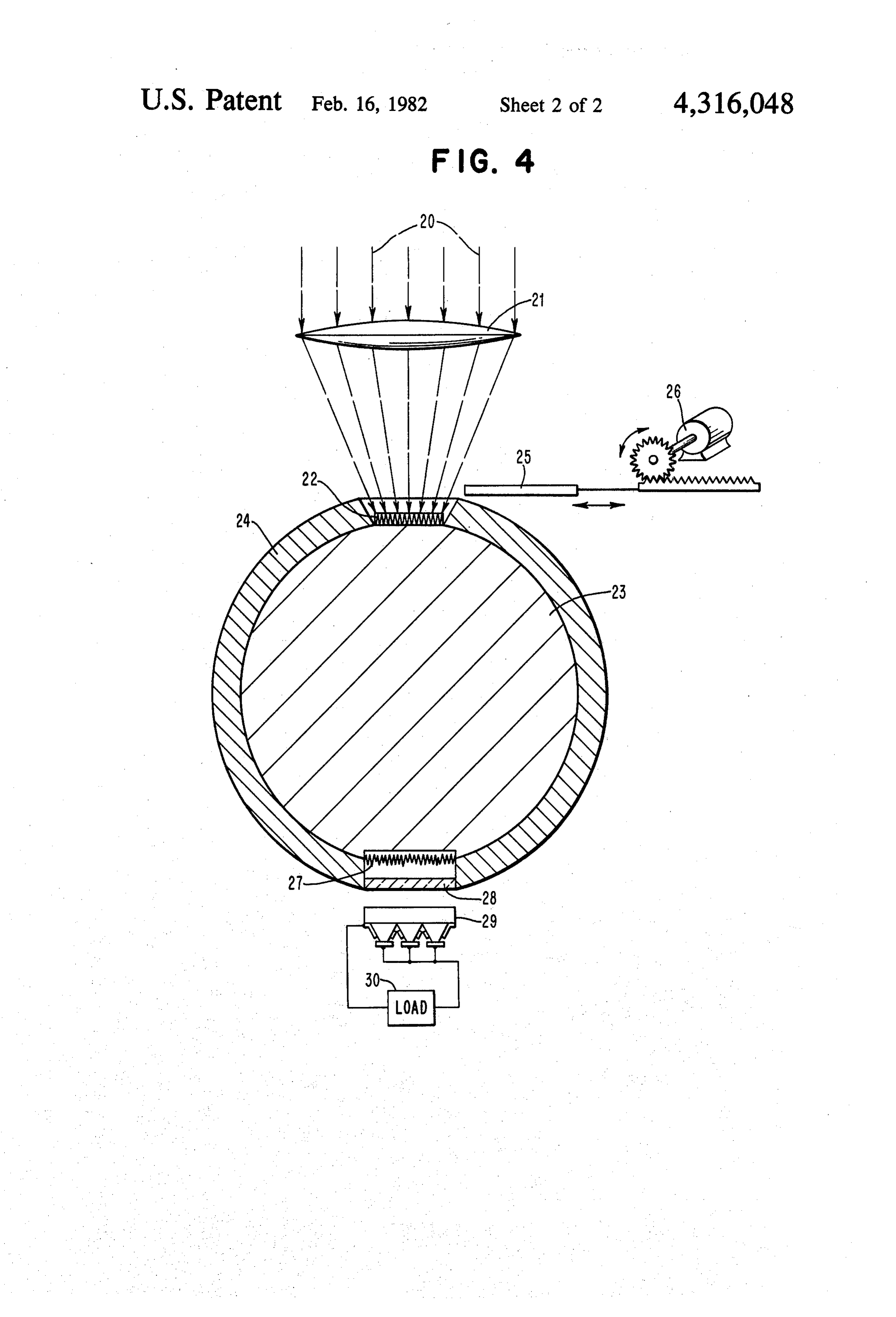
FIG. 4 is a schematic of an energy storage and con version system for solar to electrical energy.
FIG. 1 is a schematic of the elements of the energy 60 is in a useful range. Some example materials that satisfy conversion device of the invention. the criteria very satisfactorily are iron, silicon, manga FIG. 2 is a graph of the broad band wavelength of nese, chromium, and titanium.
Page 3drawing sheetscan →
Page 4scan →
Energy conversion
and the narrower wavelength band to which a photo voltaic cell is responsive.
Technical field
FIG. 4 is a schematic of an energy storage and con version system for solar to electrical energy.
The technical field of the invention is that of the 5 conversion of energy and of load leveling of energy DISCLOSURE OF THE INVENTION availability. Energy available in varying intensity and The invention involves energy conversion by reten duration is frequently desired for use in a different form tion of thermal energy supplied directly or by concen and at a different rate. It is particularly useful insteady trated radiant energy in a material having the properties electrical form but at this state of the art conversion 10 of a high thermal conductance, a high melting point and capability is limited. The major radiant energy source is a high latent heat of fusion for release to a load. the sun which emits a broad band of wavelengths but is In conversion of the energy to electrical energy only of intermittent duration. Other sources such as indus as much of the energy in a closely controlled form as a trial operations may have radiant energy and thermal photovoltaic cell can convert with high efficiency is energy available as by-products. Such sources usually 15 released. The energy is captured and stored with mini have narrower bands and different durations and wave lengths. Most thermal energy utilization operations mum loss and is then released at a possibly continuous such as space heating have excess capacity and losses thermal atophotovoltaic rate to radiant energy cell using a combination of a directional emitter and a band that could be captured in another energy form.
20 pass filter which together operate to permit only a cer
BACKGROUND ART tain range of photon energies to which a photovoltaic The desirability of energy storage for load leveling of cell can efficiently respond, to be emitted. The system purposes has been set forth in Solar Energy Thermal energy, the invention takes any source of radiant or thermal Processes, published by Wiley, New York, pages 231 to intensityeither or continuous or intermittent, at whatever rate, and collects the energy for storage in a 235, wherein current techniques such as using the latent 25 heat of melting of salts are seen to be limited by the material having the three properties in combination of a high thermal conductance, a high melting point and a amount of energy that can be stored and by the rate at high latent heat of fusion. Such a material will melt at a which it can be removed.
An effective method of using radiant or thermal en constant temperature during the absorption of energy ergy is through conversion to electrical energy. At this 30 and will freeze at the same constant temperature during state of the art, however, there is substantial room for the emission of energy. The material serves as a buffer improvement in the conversion efficiency. Further, the and is provided with efficient thermal encapsulation so generally varying intensity and intermittent nature of that the stored thermal energy can be retained for long the sources are usually incompatible with most electri periods and the thermal energy can be released at a rate cal energy applications and distribution systems which 35 independent of the input.
usually require a steady supply. The storage material of the invention has three prop The improvement efforts in conversion to electrical erties that provide the response and each of those prop energy of the radiant energy sources such as sunlight erties has a value that is related to practicability. and fuel burning cells using a photoelectric converter, The material has a high latent heat of fusion which primarily involve sophisticated solid state physics ef 40 provides the capability to store large quantities of en forts at improving the wavelength range and overall ergy. It thus has a high energy density which provides efficiency of the photovoltaic cell. It is well known at a large amount of energy storage per unit weight or this state of the art that a p-n homojunction photovol volume. Further, the smaller volume permits lower taic solar cell has a limit conversion efficiency of about energy loss due to a smaller surface area. It has been 26% for converting sunlight, which is a broad band 45 found that a latent heat of fusion value of above 1 kilo radiation source, into electricity and much room for calories per mole is in a useful range. improvement is available with such devices. The material has a high thermal conductance which There have been some other efforts in the art to con is a measure of the ability to withdraw the heat that has vert radiant energy to steady electrical energy. been stored. It has been found that a thermal conduc U.S. Pat. No. 3,929,510 for solar energy conversion 50 tance of higher than 0.1 calories per square centimeter teaches the use of a rare earth metal converter before per centimeter per degree per second is in a useful the photovoltaic cell to improve the spectral match. range.
U.S. Pat. Nos. 3,433,676 and 4,090,359 for industrial The material has a high melting point which provides energy conversion have been directed to the conversion in the molten condition a black body radiation wave of energy from continuous heat sources such as a jet 55 length distribution that is somewhat narrower and more engine and flame source to improve efficiency of the compatible with the responsiveness of the loads which electrical output. will be using the energy. The melting point should be DESCRIPTION OF THE DRAWING within a uniform defined range as the temperature is cycled. A melting point above the vicinity of 1300 K.
FIG. 1 is a schematic of the elements of the energy 60 is in a useful range. Some example materials that satisfy conversion device of the invention. the criteria very satisfactorily are iron, silicon, manga FIG. 2 is a graph of the broad band wavelength of nese, chromium, and titanium.
radiant energy. There are some practical aspects to the selection of FIG. 3 is a graph correlated with FIG. 2 showing the the storage material in that it should not be unduly rare characteristic black body radiation of material with a 65 or costly and this in turn will be sensitive to a particular high latent heat of fusion, high thermal conductance point in time. An illustration would be the element and a high melting point at melting point, and the rela silver which has a very high thermal conductance of 1 tionship between the characteristics of FIGS. 2 and 3 calorie per cm2 per cm per degree per second, a latent 5 heat of fusion of 2.7 kilocalories per mole and a melting separation of the lines approximating the center of the temperature of 920 C. so that it would appear to satisfy distribution. In a second stage the structure of elements 5 and 6 only permit release of a narrow distribution as all criteria very well. It is, however, not a very plentiful material and it has been undergoing a wide range of shown by the curve in FIG. 3 and further have the costs from $2.00 to $60.00 per ounce over about a five 5 properties that the center of that narrower distribution year period so that for this reason, at the point in time of can be moved to correspond to precise responsiveness this writing, silver would have practical but not techni specifications of the photovoltaic device 7. The nar cal disadvantages. rower distribution can not only be adjusted in width but Referring to FIG. , a schematic diagram of the ele also the peak can be adjusted.
ments of the invention is provided. In FIG. 1 a source of 10 While radiation will take place from the material 3 energy 1 such as heat or radiant energy having a broad when energy is stored in it both below and above the wavelength band as shown in FIG. 2, strikes an ab melting temperature, the most advantageous situation sorber 2. The absorber 2 which may be a broad band occurs at latent heat transfers such as at the melting photothermal converter for radiant energy or a good temperature where at constant temperature all the la thermal transfer member for heat, transfers the energy 15 tent heat of fusion can be stored until all the material 3 to an energy storage material 3. The absorber 2 in the is molten and all the latent heat of fusion can be released case of radiant energy will include a concentrator to until the material 3 is solid with the material 3 radiating insure that the temperature of the input radiation ex with the characteristics of FIG. 3 at a constant tempera ceeds that of the material 3. ture.
The storage material 3 will melt at a constant temper- 20 Where the stored thermal energy in the material 3 is ature when the rate of absorption of energy through the to be transferred as thermal energy to a heat using load, absorber 2 is greater than the rate of emission of energy an opening such as that occupied by elements 5 and 6 in from the storage member 3 out of an opening in the the housing 4 would be fitted with a thermal converter. container 4. Conversely the material 3 will solidify at The ability, in accordance with the invention, to store the same constant temperature when the rate of emis- 25 energy from either radiant or thermal sources indepen sion is greater than the rate of absorption. dent of intensity or duration wherein the storage is in a The material 3 is encased in an efficient heat retaining material having high energy density via the high latent housing 4 to minimize loss. The housing 4 is designed to heat of fusion criterion, ease of removal via the high retain the energy in such a manner that only the portion thermal conductance criterion and the predictable heat selected for release is emitted. In the case of conversion 30 characteristic via the melting point criterion, operate to to electrical energy the released portion is that which is provide a more efficient system that has been seen here useable by a particular photovoltaic device at high tofore in the art. The size is smaller, the heat can be efficiency while supplying a specific load condition. transferred out more readily and the converter that uses This is accomplished in accordance with the invention the heat can be more efficiently designed since the heat by a combination of positioning in an opening in the 35 is available under narrower specifications. housing 4 a directional thermal to radiant energy emit BEST MODE FOR CARRYING OUT THE ter 5, optically coupled to a radiant energy band pass INVENTION filter 6 and both in turn are positioned for good optical coupling to a photovoltaic device 7. Each of elements 5, In operation, referring to both FIGS. 1 and 2, energy 6 and 7 have interdependent properties such that the 40 having all or any portion thereof as a broad band of directional emitter 5 converts the thermal energy stored wavelengths of the type illustrated in FIG. 2 is intro in element 3 into radiant energy sufficiently direction duced as 1 in FIG. 1, at the absorber 2. The absorber is ally in a general sense that the band pass filter 6 can then equipped with the property that it provides maximum permit only certain photons shown as arrow 8, the en thermal transfer to the storage material 3. In the case of ergy range of which is governed by the responsiveness 45 energy 1 in the form of heat the absorber 2 will have of the photovoltaic device 7, to pass, while rejecting good thermal conductivity, and in the case of the en and turning back all other photons shown schematically ergy 1 being radiant energy, the absorber 2 will provide as arrow 9. This structure provides a controlled release wavelength independent photothermal absorption. The such that only the energy that can be efficiently used by purpose of the absorber 2 is that the maximum amount a photovoltaic device 7 is permitted to escape and the 50 of energy is extracted from the source energy 1 and is storage member 3 continues to retain all unused energy. transferred to the storage material 3. The absorber 2 is The photovoltaic device 7 has a photovoltaic junction shown schematically; however, it will be apparent to 10 across which a load 11 is connected. one skilled in the art that in achieving maximum photo The interdependent properties of the emitter 5, the thermal conversion and heat transfer such variations as filter 6 and the photovoltaic cell 7 are selectable such 55 the use of an optical concentrator or modifications in that while the source of the energy stored may vary in heat exchange sizes may be found advantageous. intensity and be intermittent, the energy that is emitted The absorber 2 may be tailored for most efficient is steady and is optimized with respect to the perfor transfer of the source of energy 1 to the material 3. mance of the photovoltaic device 7 and to the load 11 In the case of simple heat the properties of good condition. 60 thermal conduction accompanied by a melting point The overall structure of the invention operates in higher than the operating temperatures are desirable. combination to provide a closer energy matching by, in The material tungsten is satisfactory. In the case of a first stage, absorbing the broad band energy radiation radiant energy in addition to a melting point above the as shown in FIG. 2, and, as the material 3 reaches the operating temperature, the property of good photother molten stage, converting the radiative characteristics to 65 mal conversion for the specifications of the energy a different distribution as shown in FIG. 3. The distribu source is desirable. The absorptance, usually identified tion of FIG. 3 has a peak wavelength that is larger than by the symbol a should be close to 1 for near normal FIG. 2 and the distribution is offset as shown in the incidence radiation, while the hemispherical emittance, 6 usually identified in the art by the symbol e, should be approach, efficiencies over 50% are achievable in con close to 0 as possible. Such a condition can be approxi trast to the maximum at the present state of the art of mated in a structure made of refractory metal needles about 26%.
with the needles pointed in the direction of the incident In accordance with the invention, a narrow band of light. One such material is dendritic tungsten, described 5 photon energies, just above the energy band gap of the in the IBM Journal of Research and Development, Vol. photovoltaic cell 7, is selected for release by an interde 22, No. 4, July 1978, p. 372. pendent combination of a directional thermal to radiant The material of the storage material 3 has the proper energy emitter 5, a band pass filter 6 and a photovoltaic ties of high thermal conductance, high latent heat of cell 7 which are arranged such that the emitter 5 con fusion and high melting point. For good electrical con 10 verts the thermal energy to radiant energy with some version at the melting point, about 10% of the black body radiation in the high photon energy portion will direction. Only those photons shown by the schematic be absorbed by the photovoltaic cell 7 of FIG. 1. High wavelength of thewould arrow 8 which be at the peak responsiveness photovoltaic cell 7 would be permit melting point metals will satisfy these conditions quite ted to pass through the filter 6 and all others illustrated well. The element iron is particularly satisfactory, hav 15 as arrow 9 are returned and re-absorbed by the emitter ing a melting temperature of 1536 C., a latent heat of 5 and thus do not contribute to heat loss. fusion of 3.67 kilocalories per gram atom and a thermal The thermal to radiative energy emitter 5 to be direc conductance of 0.18 calories/cm2/cm/degree/second, at room temperature. A gram atom of Fe is 55.8 grams. tional should have the property that the total hemi Another material is the element Si with a melting tem 20 symbol e, emittance, spherical usually identified in the art by the is at a value of nearly 1 in a direction normal perature of 1410° C., a latent heat of fusion of 11.1 kilo to the surface and is at a value nearly 0 for all other calories per gram atom and a thermal conductance of directions. An example of a material that approximates 0.2 calories/cm2/cm/degree/second at room tempera ture. A gram atom of Si is 28.1 grams. this condition is dendritic tungsten as described in the The storage material 3 is encased in a container 4 25 4,IBM Journal of Research and Development, Vol. 22, No. July 1978, p. 372 with the needles pointed in the which is provided with the properties of low coefficient of heat transfer and low emissivity so that there is maxi direction of emission.
mum retention of heat. Since high melting point metals Band pass filters of the type required for band pass may involve temperatures above 1800 K. the material filter 6 are well known in the art and are commercially of the container 4 will probably be of a refractory type 30 available. Such filters have the property that if a wide such as boron nitride or aluminum oxide and may, in band of radiation is normally incident thereon, only a turn, be further surrounded by a reflective evacuated small preselected range of wavelengths will be transmit chamber, not shown. Since the goal of the invention is ted, while the remaining radiation will be reflected. For to retain all energy within the housing that is shown the example where the material 3 is molten iron at about schematically as element 4, except for that which is 35 1800 K. and the photovoltaic cell 7 is silicon, then the permitted to escape through controlled conditions pro band pass filter 6 will be designed to transmit and duced by the interdependent properties of elements 5, 6 thereby release photons shown as 8 in FIG. 1 having an and 7, it will be apparent that the thermal retention energy range within 1.1-1.6 electron volts and to reflect properties of element 4 to a large measure, will effect all others shown as 9 in FIG. 1 back into the material 3. the efficiency of the system. 40 One group of band pass filters well known in the art Where the source energy 1 is of an intermittent na have been made up of multiple dichroic layers. The ture, such as solar energy or where an off-duty cycle is layers are dielectric, each with a different index of re desired, the efficiency of the housing 4 may be en fraction that in combination provide transparency only hanced by the provision of a device such as a heat mir in a narrow range. Dielectric materials SiO2, TiO2, ror, not shown in FIG. 1 which would operate to pre 45 ZnO, Al2O3, Si3N4, and TaO are useable. Another type vent radiation loss from any opening and thereby pre of filter uses a semiconductor window with a band vent loss of energy. In the radiant energy type of appli energy gap of the appropriate value together with cation this would occur as the strength of the radiant proper reflectors. The filter 6 should permit only about energy becomes lower than that of the energy radiated 10% of the photons, only those having energies in the by the absorber 2 which is thermally coupled to the 50 maximum energy response range of the photovoltaic storage material 3, such as may occur in solar applica device 7 to pass so that photons emitted in a straight line tions with the approach of and during night. In a type of from the emitter 5 pass through the filter 6 whereas application where the invention is used as a portable most all other photons are reflected back and are re power supply for a vehicle or a standby power supply tained inside the container and thus do not contribute to for a piece of equipment, once an adequate energy stor 55 energy loss.
age for the purpose is complete, the container 4 could Positioned with good optical coupling to the filter 6 is be closed and only loss of energy need be periodically an efficient photovoltaic converter 7 such as the V supplied. groove multijunction silicon solar cell described in The The energy, once it is stored in the material 3, is IEEE Transactions on Electron Devices, Vol. ED-26, controllably released by emission in a wavelength band 60 July 1979, pp. 1090 to 1097. The selection of the photo as illustrated in FIG.3 and it is further only a portion of voltaic cell 7 is affected by the melting temperature of that band that photovoltaic devices of the type available material 3, the energy band gap of the material of the at this point in the art are able to respond with effi photovoltaic cell 7 and the directionality and narrow ciency. ness of the band of photon energies 8 that emanate from The efficiency of such photovoltaic devices can be 65 the combination of the emitter 5 and the band pass filter further enhanced by narrowing the emission until the 6.
photon energy is just greater than the band gap energy Referring next to FIG. 4, an embodiment of a system of the material of the photovoltaic device. With this of the energy storage of the invention is illustrated for 7 conversion of the daily energy of the sun into continu energy that is delivered or lost. Appropriate safety ous electrical power. factors for variations in supply and load should be in In FIG. 4, solar energy 20 is provided through a cluded. The quantity of material 23 should be sufficient concentrator lens 2 which focuses, at a concentration that it is never completely molten. The system is then ratio of approximately 500 to 2000 times onto an ab prevented from overheating and thereby being dam sorber 22 having properties such that the absorptance aged if not designed for it. Where the latent heat of property, usually identified in the art by the symbol C, vaporization is employed, the available heat storage is at a value of 1 and the hemispherical emittance prop capacity is greater but structural designs to handle pres erty, usually identified in the art by the symbol e, is at a sures and temperatures must be modified. value of equal to or less than 0.2. The absorber 22 pro 10 The controlled energy release structure made up of vides transfer of the radiant energy 20 into a thermal the combination of the photovoltaic cell, the band pass energy in storage material 23. filter and the directional thermal to radiant energy may The material dendritic tungsten with the needles be assembled as an aligned stack for good optical cou toward the source of radiant energy satisfies the C. and pling and minimum loss but high thermal temperatures e criteria for the absorber 22. 15 should be kept from the photovoltaic device 29 because The heat insulating container 24 is shown spherical of the temperature effect on semiconductor perfor since the spherical shape gives minimum surface area to mance and specifications regarding heat on any di volume and hence minimum area to insulate. chroic material in the filter 28 should not be exceeded. The energy storage material 23 is positioned in the The photovoltaic converter 29 should have a maxi container 24 and has the properties of not being rare or mum efficiency response that is tailored to the energy of costly, of having a high latent heat of fusion, a high the photons coming out of the band pass filter 28. The thermal conductance, and a high melting temperature at V-groove solar cell uses silicon that responds to pho which about 10% of the black body radiation thereof tons having an energy from 1.1 to 1.6 electron volts. It will be in the high photon energy range absorbable by a involves multiple internal reflections and provides very photovoltaic cell. The materials iron and silicon each 25 high efficiency. Under conditions where the properties satisfy these properties. of emitter 27 and filter 28 are such that only photons in A member 25 is provided to prevent radiation out of the responsive range are transmitted, the V-groove the opening in the insulating container under conditions multijunction solar cell is expected to convert at an such as when the sun goes down. The member 25 is a efficiency greater than 50% and the total conversion heat mirror positioned by movement apparatus 26 30 efficiency of the storage system will be in the vicinity of shown as a motor and gear arrangement to cover the 40%.
absorber 22 opening. A similar structure can be pro The material 3 will remain continuously at the melt vided to control emission from any opening. ing temperature whether the amount of heat coming in At a point in time such as when the sun is down or is exceeding that released and the molten portion is when the release to the load should be interrupted, the 35 increasing or the opposite condition where more heat is apparatus 26 moves the mirror 25 over the opening. being released than is coming in and the molten portion For simplicity of illustration purposes, the container is decreasing.
24 is shown of a single material such as, for example, The following examples are an illustration of system boron nitride and aluminum oxide, the properties of performance using as an assumption for a solar energy which are good heat insulation and low emissivity. In 40 application an eight hour average daily sunlight period fact, however, the higher the retention properties of the and using a 1-square meter concentrator lens 21 which container 24, the greater will be the efficiency of the provides 1 kilowatt impinging on absorber 22 for 8 entire system so that the container 24 may further be hours which provides 8 kilowatts per day. Where the surrounded with an evacuated container or other struc material 23 is iron (Fe), with a melting temperature ture. Accommodation may also be necessary for pres 45 (Tm) of 1536 C., an atomic weight of 55.8 grams/cc, a sure change and expansion. This would be of particular density (p) of 7.87gms/cc, a latentheat of fusion (AH) importance if the material 23 were to be operated using of 3.67 kilocalories/mole and a thermal conductance of the property of the latent heat of vaporization. The 0.18 calories/cm2cm/degree/second, at room tempera preferred type of operation employs the latent heat of ture, then for 8 kilowatt hours of storage there will be melting because of the radiative characteristic advan 50 required 106 kilograms or 233 lbs., occupying a volume tages of FIG. 3. The energy stored by melting the stor of 13.5 liters which in turn is a containment sphere of age material 23 is selectively let out during freezing of radius 14.7 centimeters.
the material 23 at the maximum efficiency of a photo Where the material is silicon (Si) with a melting tem voltaic cell 29 and for maximum use in a load 30 ar perature (Tm) of 1410 C., an atomic weight of 28.1, a rangement. 55 density (p) of 2.35, a latent heat of fusion (AH?) of 11.1 When the sun is the source of radiant energy, the kilocalories per mole and a thermal conductivity of 0.2 amount of material 23 that will be needed will depend calories/cm2/cm/degree/second, at room temperature, on the energy density impinging on absorber 22 during then for 8 hours of storage there will be required 14.7 available time, i.e., the daylight, and the electrical en kilograms or 38 lbs., occupying a volume of 7.41 liters ergy to be continuously delivered to the load 30. The 60 which in turn is a containment sphere of radius 12.0 quantity of material 23 is chosen such that for a particu centimeters.
lar day at dawn, the material 23 would be almost en The 8 Kw energy stored in the 14.7 or 12.0 cm radius tirely frozen whereas at dusk it would be almost entirely sphere of Fe or Si, respectively, at an assumed tempera molten. ture of the vicinity of 1800 K. is selectively released as The system preferably uses the latent heat of fusion of 65 photons with an energy that is in the responsive range material 23 and remains at a constant melting point of a photovoltaic cell through the use of a thermal to temperature. The relative fraction that is molten will radiant energy emitter 27 and band pass filter 28 combi depend upon the cumulative energy received minus the nation. This type of energy transfer can be approxi 8 mated in practice by using dendritic tungsten with the energy output release means for delivering a portion of needles in the direction of emission as the emitter 27 . . the energy stored in said material to a load under positioned in a tandem arrangement with a band pass conditions responsive to the requirements, of said filter 28 made up of an intrinsic semiconductor window load. . .. . - with a band gap energy corresponding to the desired 2. The system of claim 1 wherein said container is high photon energy cutoff of responsiveness", of the spherical. , ,, . - photovoltaic device 29 that is coated with a transparent 3. The system of claim 1 wherein said energy input reflective layer such as a dielectric oxide and a heat means is a radiant energy to thermal energy converter. mirror such as glass coated with a conductive oxide 4. The system of claim 3 wherein said energy output such as tin oxide. The reflective layer on the semicon 10 release means includes a thermal energy to a selected ductor window and the heat mirror in combination optical energy wavelength band converter. operate to reflect photons that have either too high or 5. The system of claim 4 wherein said energy output too low an energy to be passed by the semiconductor release means includes a photovoltaic device having window. For a photovoltaic device 29 with peak effi high efficiency response at said selected optical energy ciency responsiveness to photons in the 1.1 to 1.6 elec 15 wavelength band.
tron volt range, the semiconductor window could be a 6. The system of claim 5 wherein said energy storage cadmium telluride (CdTe) crystal 50 mils thick or a material is a member of the group of iron, silicon, man hydrogenated amorphous silicon layer (a-Si:H) 10 mils ganese, chromium and titanium.
thick, coated with 1300 to 1600 A of SiO2 or TiO2 in 7. The system of claim 1 wherein said energy output tandem with and preceded by a heat mirror of SnO 20 release means includes a thermal energy to a selected coated glass. optical energy wavelength band converter. An emitter 27 of dendritic tungsten at 1800 K. would 8. An energy system comprising in combination: be emitting 75 watts/cm2 with a hemispherical emissiv thermally insulated energy storage confinement ity of 1 but with an assumed average emissivity of 0.2 it means;
would emit 15 watts/cm2. Assuming the area of the 25 energy storage material within said confinement emitter 27 to be 200 cm2, there will be 3000 watts emit means, said material having the combined charac ted and the band pass filter 28 will reflect 2700 watts teristics of a thermal conductance in excess of 0.1 that do not have the correct range of photon energy. calorie per square centimeter per centimeter per The 300 watts that are passed represent 7.2 Kwh over degree per second at room temperature, a latent 24 hours or a loss of 0.8Kwh in the storage portion of 30 heat of fusion of the order of 1 kilocalorie per mole the system. The 300 watts are converted in the V and a melting point in the vicinity of 1300" Kelvin groove multijunction photovoltaic device 29 at a 50% and above;
efficiency, providing 3.6 Kwh over a 24 hour day. energy input means for delivering source energy Thus, a sphere approximately 10 inches in diameter will outside said container as thermal energy to said store in 8 hours enough energy to supply a horse 35 material; and power motor for 24 hours with approximately a light energy output release means for delivering a portion input through a concentrator 100 cm on a side and a of the energy from said material to said load under photovoltaic device output that is about 14 cm on a side. conditions responsive to the requirements of said In a situation where there is a variable electrical load load.
connected to cell 29, some energy efficiency accommo 40 9. The system of claim 8 wherein said energy input dation can be provided with an optical imaging system means is a radiant energy to thermal energy converter. with a reflective diaphram interposed between filter 28 10. The system of claim 9 wherein said thermal en and cell 29 to recycle excess photons during low de ergy converter is dendritic tungsten.
mand periods. Alternatively, electrical power could be 11. The system of claim 9 wherein said energy output fed back into material 23 from cell 29 resistively as heat 45 release means includes a thermal energy to a selected in low demand load periods or the opening could be optical energy wavelength band converter. controlled through an apparatus similar to 25 and 26. 12. The system of claim 11 wherein said thermal What has been described is a system of buffering and energy to optical energy converter includes a thermal converting energy so as to provide for multiple energy to radiant energy emitter optically coupled to a selected types, in densities and durations at the input and multi 50 photon energy transmitting member. ple types of output of selectable duration and intensity. 13. The system of claim 12 wherein said transmitting Having described the invention, what is claimed as member is a band pass filter.
new and what is desired to secure by Letters Patent is: 14. The system of claim 12 wherein said transmitting 1. An energy system comprising in combination: member is a selected photon energy passing semicon a thermally insulated energy storage container; 55 ductor window with associated non-selected energy an energy storage material within said container, reflecting members.
said energy storage material having the combined 15. The system of claim 8 wherein said energy output characteristics of: release means includes a thermal energy to a selected a thermal conductance in excess of 0.1 calorie per optical energy wavelength band converter. square centimeter per centimeter per degree per 60 16. The system of claim 15 wherein said output means second at room temperature, also includes a photovoltaic converter efficiently re a latent heat of fusion of the order of 1 Kilocalorie sponsive and optically coupled to said converter. per mole, and 17. The system of claim 16 wherein said energy stor a melting point in the vicinity of 1300 Kelvin and age material is a member of the group of iron, silicon, above; 65 manganese, chromium and titanium, said input means energy input means for delivering source energy out includes a dendritic tungsten absorber positioned with side said container as thermal energy to said material; the dendritic needles in the direction of said radiant and energy, said energy release means includes a dendritic 9 tungsten emitter positioned with the needles away from a thermal conductance in excess of 0.1 calorie per said storage material, a 1.1 to 1.6 electron volt photon square centimeter per centimeter per degree per band pass filter optically coupled to said emitter, and a second at room temperature, V-groove multijunction solar cell optically coupled to a latent heat of fusion of the order of 1 Kilocalorie said band pass filter. per mole and 18. In an energy conversion system of the type a melting point in the vicinity of 1300 Kelvin and above, wherein energy supplied by a source having intensity means delivering and/or duration variation is to be connected to a load radiation from said storage member to an optically coupled photovoltaic member, and having a varying magnitude and/or duration of energy 10 means connecting the output usage the improvement comprising: of said photovoltaic mem ber to said load.
means for delivering energy from said source as thermal 19. The system of claim 18 wherein said material is a energy to a storage member, member of the group of iron, silicon, manganese, chro said storage member being a material having the com mium and titanium.
bined characteristics of 15 k k 3k k k
Provenance
- Collection
- Patents citing this work
- Pages
- 9
- Method
- pdftotext (the PDF's own text layer) + pdftoppm 300dpi page scans
- Patent office record
- patents.google.com →
- Source
- Google Patents citing-documents table
- Assignee
- International Business Machines Corporation
- Published
- 1982-02-16
- Transcribed from
- patentimages.storage.googleapis.com →