

patent · US4319141A
Turbine configurations using wind and solar power
9 March 1982
Text
Page 1bibliographic recordscan →
United States Patent (19)
Schmugge
54 TURBINE CONFIGURATIONS USING WIND
AND SOLAR POWER
76 Inventor: Frederick K. Schmugge, One Salem
Rd., East Brunswick, N.J. 08816
Int. Cl. ................................................ FO2C 1/04 52 U.S.C. ......................................... 290/52; 60/398 (58) Field of Search ..................... 290/52; 415/2, 2A,
Re. 30,136 11/1979 Schriefer, Jr. ...................... 126/441
695,525 3/1902 Wuest .................................. 160/247 1,939,317 12/1933 Pope ............ ... 45/147 3,048,006 12/1960 Goodman ............................. 290/55 3,484,617 12/1969 Winsel ................................... 290/44 3,514,942 6/1970 Kyryluk. . 60/461.15 3,720,840 3/1973 Gregg ... ... 546/266 3,936,652 2/1976 Levine .................................. 290/10 4,018,543 4/1977 Carson et al. ... 415/2 R 4,031, 173 6/1977 Rogers ............ ..., 260/124 4,088,266 5/1978 Keyes .......... ... 237/1 A 4,118,636 10/1978 Christian . ... 290/510 4,122,675 10/1978 Polyak .................................. 60/398
FOREIGN PATENT DOCUMENTS
Primary Examiner-J. D. Miller
Assistant Examiner-D. L. Rebsch
Attorney, Agent, or Firm-Wilson, Fraser, Barker &
Clemens
A power system comprises structures which capture wind and solar energy to drive turbines for generating power. The structures can assume different forms, some intended to operate only from wind power. All in com mon, however, have lower air intake means which can accept the wind from any direction, air passageways that conduct the air upward through turbines, and ven turi-assisted upper air exhaust vents which discharge the air downwind. Structures intended to operate on solar power in addition to wind have generally trans parent sun-facing outer surfaces to admit solar radiation into the air passageways, a heat absorbing and transfer ring means inside the air passageways, and sufficient height that the solar heated air will rise with adequate velocity to operate the turbines. The invention includes an air inlet louver configuration which permits free entry of normal winds, but restricts entry of winds that have excessive force.
2 Claims, 16 Drawing Figures
Drawings
Page 2drawing sheetscan →
Page 3drawing sheetscan →
Page 4drawing sheetscan →
Page 5drawing sheetscan →
Page 6scan →
of the expanding heated air, or to both effects com
TURBINE CONFIGURATIONS USING WIND AND bined.
SOLAR POWER At the top of the structure, the air is ducted to one or more cylindrical exhaust towers or stacks. These each
BACKGROUND OF THE INVENTION 5 contain an electric generator connected to a turbine 1. Field of the Invention operated by the moving mass of air. These stacks may Since other energy sources are limited in availability be or short, of sufficient length only to house the turbines;
they may be quite tall, to increase the velocity of the (example: fossil fuels and hydroelectric power) or pro rising heated air. If tall, they may be equipped for addi duce pollution, (example: nuclear power and some fossil 10 tional solar heating of the rising air. In such case, their fuels), there is need for efficient, dependable means for exterior skin will consist using wind and solar power, both of which are plentiful rial, and their interior willofcontaingenerally transparent mate heat transfer means, and non-polluting. This invention combines both such as concentric cylinders or black-painted metal sources in one power generation system. SCteel.
2. Description of the Prior Art
Several U.S. Patents, such as U.S. Pat. No. 695,524 airAtexhaust the top of each tower or stack is a venturi-assisted and U.S. Pat. No. 3,936,652, describe propellors or downward, device, and which swivels to discharge the air which reduces pressure at the top of the turbines powered by heated air rising in a flue. Others, stack, thus increasing the upward air velocity through such as U.S. Pat. No. 3,514,942 and U.S. Pat. No. the stack.
4,118,636, describe turbines driven by solar heated air. 20 To prevent turbine damage due to excessive velocity U.S. Pat. No. 3,720,840 describes a ductwork through in very strong winds, the air inlets have a louver config which wind is carried to a turbine, and in which the output can be supplemented by heating the air in the uration which restricts the air inlet openings when the air velocity is high.
exhaust stack. Some, such as U.S. Pat. No. 4,018,543, The solar heating air passageways on the main struc describe devices operated only by wind, in which the 25 ture may be constructed to store some of the solar heat air is carried by ductwork to the turbine. and release it later to cooler air. This tends to minimize This invention uniquely and significantly goes be output fluctuations due to passing clouds. yond these, and provides a system combining both wind Unneeded electric power may be used to separate and solar energy to provide power without polluting water into its hydrogen and oxygen components. The the environment. 30 hydrogen will be burned to provide heated air for oper SUMMARY OF THE INVENTION ation of the turbines whenever solar and wind power The invention includes a lower air inlet means which are insufficient. The oxygen and any surplus hydrogen will be sold commercially.
can accept air from the direction of the wind, means for This total system provides an efficient, dependable, directing the passage of air upward through a windmill 35 non-polluting power source.
or turbine mounted on a vertical axis, and upper air Differing configurations will adapt this system to exhaust means which discharge the air downward. In different locations, such as equatorial areas where the most cases, it also includes means for solar heating the sun passes somewhat directly overhead, or off-shore air, and has sufficient height to cause the heated air to locations where the structure may be floating or con rise upward with considerable velocity. In its full and 40 structed on stilts or pilings. The system may also be exemplary form, this invention is embodied by a com added to existing buildings, in which case the structure mercial power plant, operating from both wind and configuration will be determined largely by the charac solar energy. It comprises a large structure in which teristics of each particular building. Structures built for much of the interior space may be put to other uses, lesser needs might omit some of the features of the such as offices, department store, apartments, etc. Some 45 system. For example, an individual farm home might of the interior space could be used for hydrogen and have a small configuration using only wind power. oxygen storage tanks, as described later; but external storage of these gases would be preferable in most cases, BRIEF DESCRIPTION OF THE DRAWINGS for safety considerations. The above objects and advantages of the invention The lower area of the structure contains air inlets on 50 will become readily apparent to one skilled in the art all sides, so as to permit the wind to enter from any from reading the following detailed description of an direction. embodiment of the invention when considered in light The sun-facing side of the structure is slanted for of the accompanying drawings, in which:
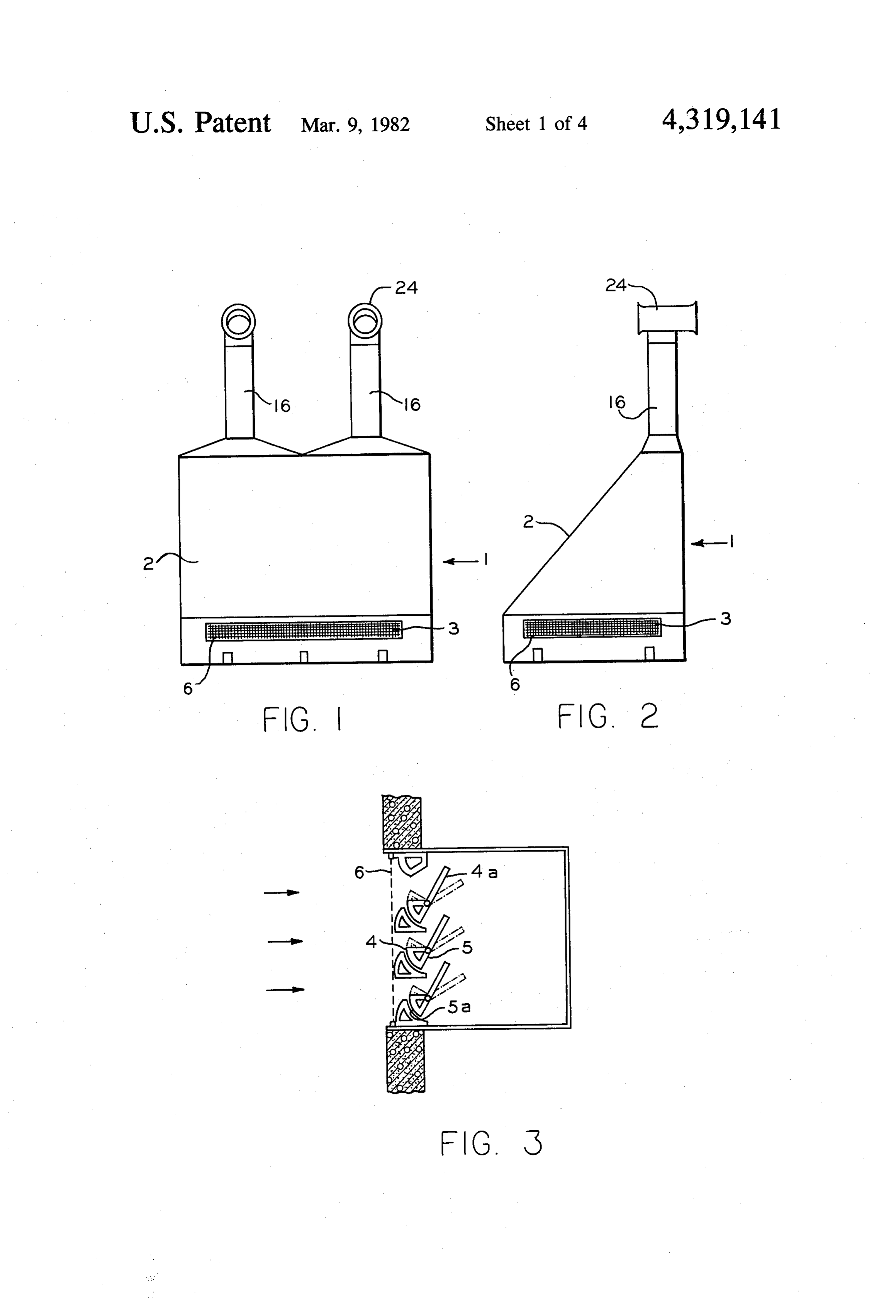
maximum exposure to the sun, depending on the lati FIG. 1 is a front elevational view of a power plant tude of its location. The exterior of this sun-facing side 55 structure embodying the invention; comprises air passageways for solar heating of the air. FIG. 2 is a side elevational view of the structure These are glazed with a generally transparent material illustrated in FIG. 1;
to permit entry of solar radiation. The interior of these FIG. 3 is a sectional view showing in detail the con air passageways contains a means for absorbing the struction of typical inlet louvers;
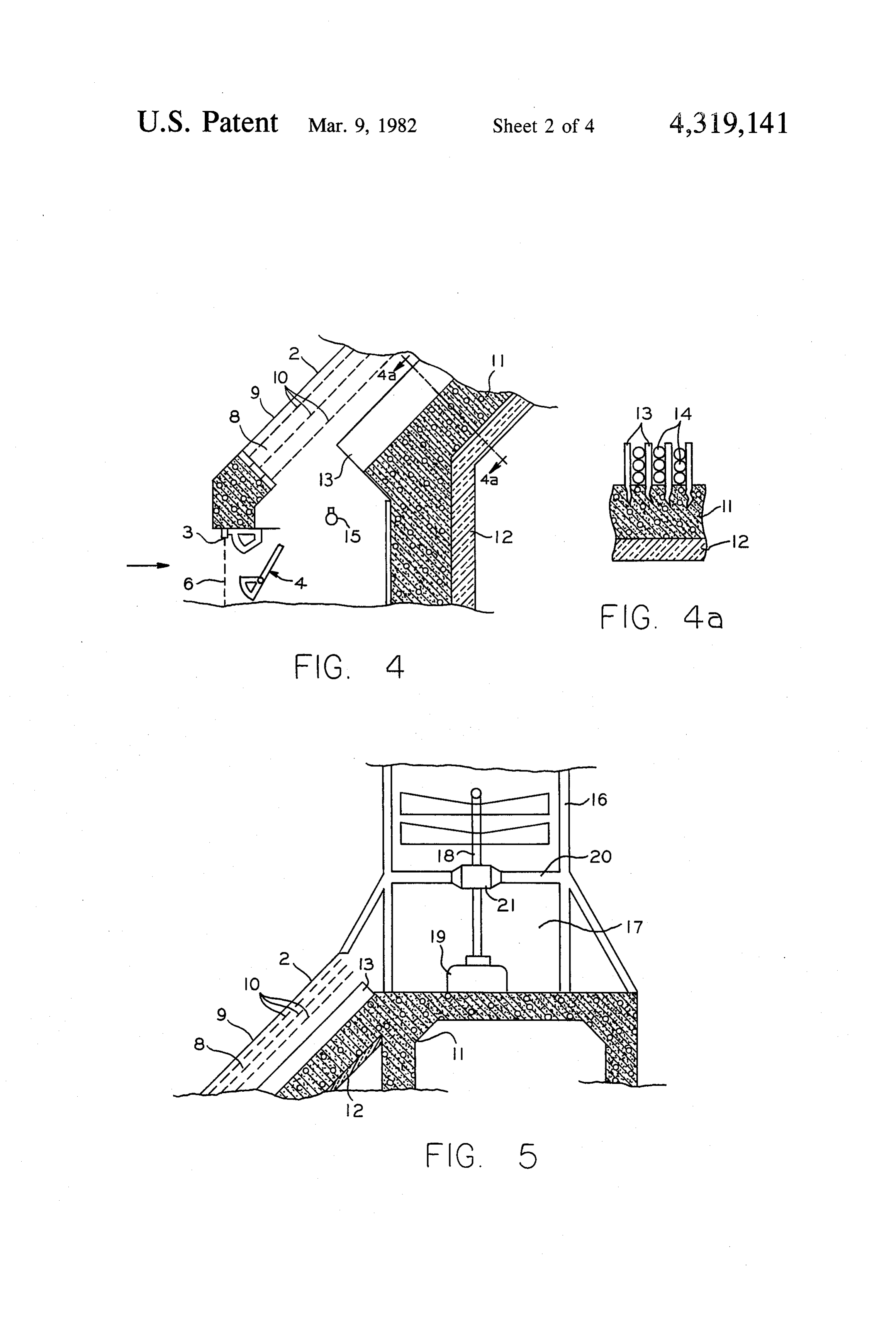
solar heat and transferring it to the air, such as several 60 FIG. 4 is a sectional view illustrating a solar heated separated layers of black-painted metal screen. The east air passageway;
and west sides of the structure, which are generally FIG. 4a is a sectional view taken on the plane 4a-4a vertical, may also have such solar heating air passage of FIG. 4 illustrating heat absorption means; ways in order to utilize radiation from the early morn FIG. 5 is a sectional view illustrating a typical con ing and late afternoon sun. Air from the inlets is brought 65 struction of the upper air passageway, the air plenum by ductwork to these solar heating air passageways, and turbine;
where it moves upward. This upward air movement FIG. 6 is a sectional view of an exhaust stack, illus may be due to the outside wind pressure, or to the rising trating additional heat absorption means;
Page 7scan →
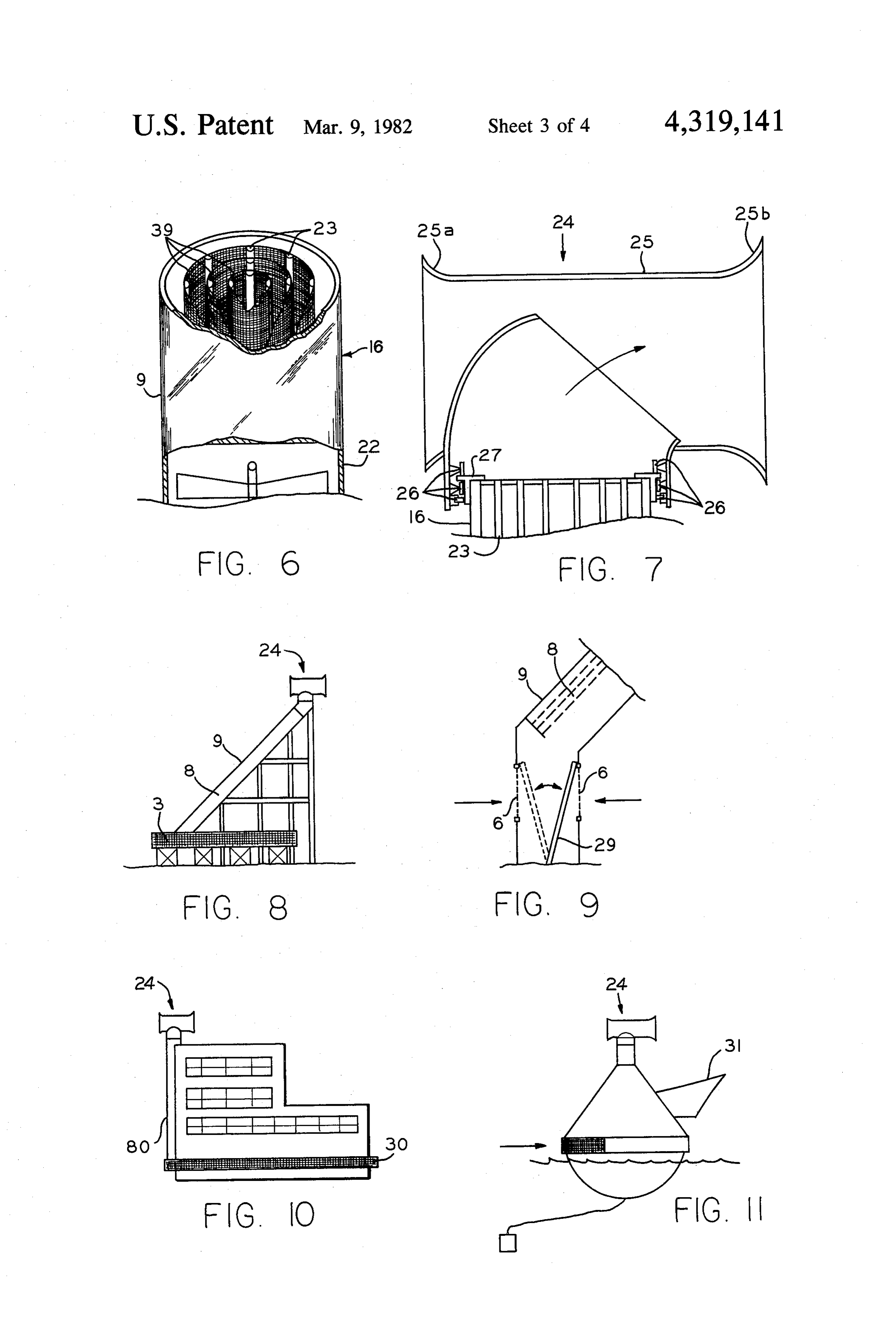
FIG. 7 is a sectional view of a venturi exhaust tube heating air passageways 8, a layer of insulation 12 insu mounted on an exhaust stack; lates the concrete wall 11 from the structure's interior FIG. 8 is a side elevational view of an alternative allowing the wall 11 to store solar heat for release later structure for a power plant embodying the invention. to cooler air. A plurality of black-painted metal fins 13 FIG. 9 is a schematic sectional view of air inlet means project from the wall 11 to facilitate transfer of heat to for controlling the direction of inlet air; the concrete. They may be imbedded into the concrete, FIG. 10 is a side elevational view of a building struc as shown in FIG. 4A, and may also enclose containers ture retrofitted to embody the concepts of the inven of eutectic salts 14 for additional and more efficient heat tion; storage. Dividing walls between the solar heating air FIG. 11 is a side elevational view of a floatable struc 10 passageways, which provide the support for the glazing ture embodying the invention; and the metal screens, are not shown. A gas burning FIG. 12 is an elevational view of a power plant struc orifice 15 is provided at the bottom of the passage 8 to ture embodying the invention, suitable for tropical lati heat the air for operation of the system when solar and tudes; wind power are insufficient.
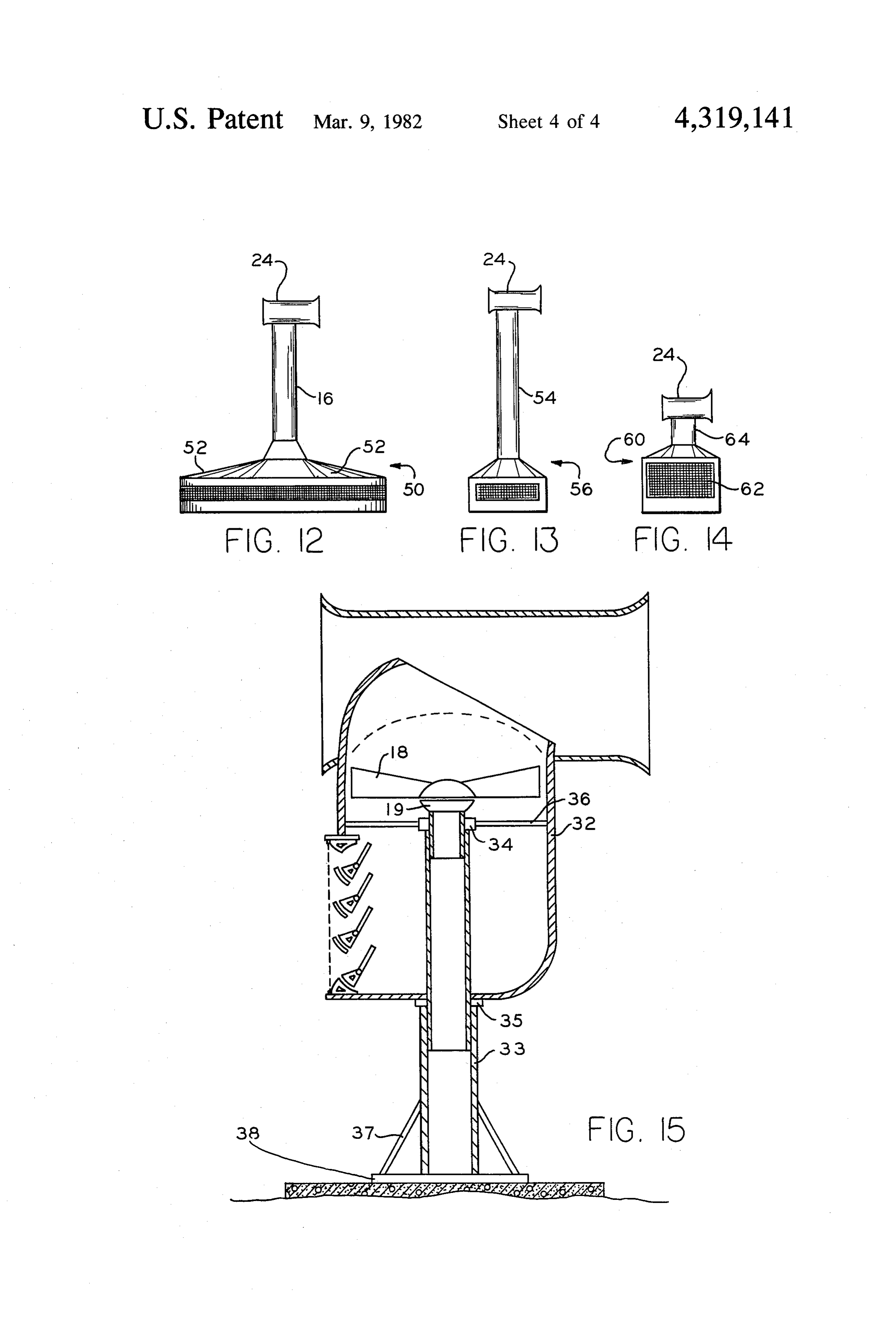
FIG. 13 is an elevational view of an alternative struc 15 FIG. 5 shows a vertical cross sectional view of the ture in which solar heating is accomplished only in a base of a cylindrical exhaust stack 16 and shows a prac transparent stack; tical arrangement of the turbine 18 and an electric gen FIG. 14 is an elevational view of a power plant struc erator 19. However, it is not intended to rule out other ture utilizing only wind power; and, arrangements, nor is it intended to restrict use of the FIG. 15 is an sectional view of an alternate configura 20 turbine output only to generation of electricity. At the tion which drives a turbine by wind power only. base of the stack 16 is a plenum space 17 by which the DESCRIPTION OF THE PREFERRED rising air from all solar heating air passageways 8 is EMBODIMENT carried to the turbine 18 in the exhaust stack 16. Struc tural webbing 20 supports a turbine shaft bearing 21.
An exemplary full implementation of this invention 25 FIG. 6 shows a vertical cross sectional view of a tall comprises a large building structure 1 having a transpar exhaust stack 16 equipped for additional heating of the ent, inclined, solar facing wall 2 which encloses air rising air. Stack 16 comprises a cylindrical framework passageways 8. Air flow is through inlets 3, through 22 covered by transparent glazing 9. The interior has passageways 8, through a plenum 17, past a wind tur additional frame members 23 which support concentric bine 18, and through an exhaust stack 16. The entire 30 cylinders of black-painted screen 39 for solar heat ab structure , therefore comprises a means for channeling sorbtion and transfer thereof to the air. wind and solar heated air through a turbine. Most of the FIG. 7 shows a cross sectional view of the exhaust interior of the structure 1 may be used for such other vent 24 at the top of the stack 16. Although other air purposes as providing office space. exhaust vent devices are available and could be used in Screened air inlets 3 are located on the sides of the 35 this application, the preferred embodiment includes a structure 1, and are preferably of equal area on each side venturi-assisted vent 24 which will create a substantially of the structure 1. The inlets 3 are covered by protec lower pressure to increase the flow of air through the tive screens 6. Although these air inlets 3 could have turbine 18. A generally cylindrical shroud 25 having a louvers which are operated electrically to open accord restricted central section acts as a wind vane to turn the ing to the sensed wind direction, and to partially close if 40 vent assembly so the air is always discharged down the wind velocity is excessive, this invention includes a wind. It also acts as a venturi tube, in that the air mov self-operating configuration of louvers 4, as illustrated ing through the restricted section reduces air pressure at in cross section in FIG. 3. The louvers 4 are pivotally the top of the stack 16. The front 25a of the shroud 25 mounted. Counterweights 5 at the bottom of the louvers may be slightly belled to increase the volume of air 4 normally hold louver vanes 4a in a vertical position 45 blowing through the shroud 25; the rear 25b may be closing the inlets 3. Positive pressure in the ductwork belled even more to increase the wind vane characteris also tends to hold the louvers 4 closed on all except the tics. The usefulness of such a venturi-assisted exhaust windward side. Either a positive outside pressure from vent 25 should not be considered as restricted to these the wind, or a negative inside pressure caused by rising turbine devices, but will have other uses, such as venti heated air, pivots the louver vanes 4a open, as shown by 50 lating barns and attics, etc. The configuration of the solid lines in FIG. 3, to permit air to enter. Strong exhaust vent 24 shown in FIG. 7 has a plurality of guide winds, which could cause excessive turbine velocity, wheels 26 running on a circular T-beam track 27 at the pivot the louver vanes 4a so that lower surfaces. 5a of top of the stack 16. Guide wheels 26 anchor the exhaust counterweights 5 begin to close off the openings and vent 24 firmly, but permit it to rotate freely with the restrict the air flow, as shown in dotted lines in FIG. 3. 55 wind. Other bearing means could be used. For example, FIG. 4 shows a cross sectional view through the a small attic ventilator might have only a nylon ring as lower portion of the solar heating air passageways 8. a bearing surface.
The solar heating air passageways 8 may be spaced so as A comprehensive energy storage system includes a to allow for windows or skylights between them, or separate Structure containing equipment for separating may be intermixed with other solar panels which could 60 water into hydrogen and oxygen, and tanks for storing provide heating for the structure's interior. Glazing 9, these two gases. In this way, unneeded electric power of a generally transparent material, forms the outer wall may be stored. Burning the hydrogen through the gas of the passage 8, and permits solar radiation to enter. burning orifice 15 permits turbine operation when wind Several separated layers of black-painted metal screen and solar power are insufficient. In emergencies, natural 10 are positioned within the passageways 8 to absorb 65 gas could be burned.
solar radiation and transfer it to the air. Structural con Thus far, the fullest implementation of the invention crete or other structural material forms the inside wall 11 of passageway 8. If concrete is used behind the solar Also,been has described. Some capabilities may be omitted.
as said earlier, the design of the structures may 8 take many forms. In FIG. 8 is illustrated an embodiment mounting plate 38, which is fastened to a concrete base of the invention for use where an enclosed structure is or otherwise secured. Although an electric generator is not desired. If located in an area where the winds are preferred to produce usable energy output, it should be predominantly north and south, the side air intakes 3 understood that the turbine output could be used for may be omitted. In this case, and if other provision is other purposes also, such as operation of a water pump made to prevent turbine damage from excessive winds by means of a shaft extending down the central support (for example, feathering the turbine blades), the air column.
intake configuration can be very simple, as illustrated in In accordance with the provisions of the patent stat FIG. 9. A panel 29, hinged at the bottom, flops from utes, the principle and mode of operation of the appara one screened air inlet 6 to the other according to wind 10 tus have been explained and what is considered to rep direction, sealing the downwind inlet to prevent the resent its best embodiment has been illustrated and de wind from blowing straight through. scribed. It should, however, be understood that the FIG. 10 pictures a possible adaptation of this inven invention may be practiced otherwise than as specifi tion to an existing building. An air inlet ductwork 30 is cally illustrated and described, without departing from attached to the lower area of the building, to carry air 15 its spirit or scope.
from any direction to the solar heating air passageways What is claimed is:
80 attached to the sunfacing side of the building. 1. A power system for channeling wind and solar A very efficient site for locating the power plants heated air to drive a turbine, comprising: air inlets; embodying this invention is off-shore where wind and means for selectively opening said air inlets in an up sun are unhampered. Structures as already described 20 ward direction; means responsive to wind in excess of a can be built on stilts or pilings. Or they could be built as predetermined velocity for partially closing said inlets; large floating structures, as in FIG. 11, which could be means for absorbing solar radiation and for heating towed to off-shore locations and anchored wherever collected air by conduction; passageway means for needed. The floating structure has a generally conical collecting inlet air and channeling it into contact with configuration, shaped somewhat like an upside down 25 said air heating means, said passageway means includ funnel. Its windvane 31 always keeps its air inlet pointed ing a transparent extended surface portion adapted to into the wind. The hydrogen and oxygen generation normally face the sun and an opaque extended surface and storage facilities for such off-shore applications radiation absorbing portion opposite the transparent would be enclosed within the structure. surface; an air exhaust stack spaced above said passage In equatorial areas, where the sun passes more nearly 30 way means, said exhaust stack having a cross-sectional directly overhead, solar heating air passageways should area generally normal to the direction of air flow sub be more nearly horizontal. A preferred embodiment of stantially less than the cross-sectional area of said pas the invention for these regions is illustrated in FIG. 12. sageway means generally normal to the direction of air The structure 50 for such regions has a generally trans flow, whereby air velocity within said stack is in parent top wall 52 of shallow conical configuration, the 35 creased; an air plenum between said passageway means surface of which is inclined at a small angle to horizon and said exhaust stack arranged to collect and channel tal. The wall 52 composes the outside wall of the solar rising air into said stack; and an air powered turbine heating air passageways, as already described. The between said passageway means and the top of said structures of the stack 16 and exhaust vent 24 are also as exhaust stack.
described for the embodiment illustrated in FIG. 1. 40 2. A power system for channeling wind and solar A further embodiment, suitable for limited space heated air to drive a turbine, comprising: air inlets; installation is illustrated in FIG, 13. In this embodiment pivotally mounted louver vanes and counterweights solar heating is accomplished only in the transparent attached thereto for selectively opening said inlets stack 54. The bottom 56 of the structure, not being toward an upwind direction, said louver vanes extend provided with solar heating air passageways, is of a 45 ing upwardly from the pivot point of said louver vanes, compact configuration. Other features of the invention, and said counterweights depending from said pivot in particular the venturi exhaust vent 24, are as already point, including secondary vanes below the pivot point described. - arranged to partially close said inlets when high winds If only wind power is desired to drive a turbine, the cause said louvers and counterweights to pivot beyond invention may be embodied in the structure 60 illus 50 a preselected angle; means for absorbing solar radiation trated in FIG. 14. This structure has relatively tall air and for heating collected air by conduction; passage inlets 62, and a relatively short exhaust stack 64, which way means for collecing inlet air and channeling it into may also have a venturi-assisted vent 24. The structure contact with said air heating means, said passageway 60 utilizes the air inlet 62, a turbine on a vertical axis, an means including a transparent extended surface portion exhaust stack, and other features as previously de 55 adapted to normally face the sun and an opaque ex scribed, but does not have solar heating means. tended surface radiation absorbing portion opposite the FIG. 15 shows still another configuration intended transparent surface; an air exhaust stack spaced above for only wind operation. It, too, utilizes a lower air inlet, said passageway means, said exhaust stack having a upward passage of air through a turbine, and an upper cross-sectional area generally normal to the direction of air exhaust, which are typical of this invention, but does 60 air flow substantially less than the cross-sectional area not provide for heating of the air. The entire housing 32 of said passageway means generally normal to the direc is supported on a central column 33 by means of upper tion of air flow, whereby air velocity within said stack and lower bearings 34 and 35 which allow the housing is increased; an air plenum between said passageway 32 to rotate freely with the wind. A plurality of radial means and said exhaust stack arranged to collect and arms support the upper bearing 34. The electric genera 65 channel rising air in said stack; and an air powered tor 19 and its driving turbine 18 are mounted at the top turbine between said passageway means and the top of of the central support column 33. A reinforcing web 37 said exhaust stack.
helps to secure the central column 33 to the bottom k 3 - 2 k.
Page 9scan →
United states patent and trademark office
Certificate of correction
INVENTOR(S) : Frederick K. Schmugge
It is Certified that error appears in the above-identified patent and that said Letters Patent are hereby Corrected as shown below:
Column l, line 37, "downward" should read --downwind--. Column 2, line l3, "or" should read --of--, and line l7 "downward" should read --downwind--. signed and Sealed this
Eighth Day of June 1982
Seal
Attest:
Gerald j. mossinghoff
Attesting Officer Commissioner of Patents and Trademarks
Page 10scan →
United states patent and trademark office
Certificate of correction
INVENTOR(S) : Frederick K. Schmugge
It is Certified that error appears in the above-identified patent and that said Letters Patent are hereby corrected as shown below:
Column l, line 37, "downward" should read --downwind--. Column 2, line l3, "or" should read --of--, and line l7 "downward" should read --downwind--.
signed and Sealed this
Eighth Day of June 1982
Seal
Attest
Geraldj. mossinghoff
Attesting Officer Commissioner of Patents and Trademarks
Provenance
- Collection
- Patents citing this work
- Pages
- 10
- Method
- pdftotext (the PDF's own text layer) + pdftoppm 300dpi page scans
- Patent office record
- patents.google.com →
- Source
- Google Patents citing-documents table
- Assignee
- Schmugge Frederick K
- Published
- 1982-03-09
- Transcribed from
- patentimages.storage.googleapis.com →