

patent · US4319892A
Magnetically stabilized bed, temperature, partial pressure swing, hydrogen recovery process
16 March 1982
Text
Page 1bibliographic recordscan →
United States Patent (19) 4,319,892 Waghorne et al. (45) Mar. 16, 1982 54 MAGNETICALLY STABILIZED BED, from a feed gas or vapor which contains hydrogen in TEMPERATURE, PARTIAL PRESSURE admixture with one or more hydrocarbon components, SWING, HYDROGEN RECOVERY PROCESS alone or in admixture with non-hydrocarbon compo Inventors: Robert H. Waghorne; Martin O. nents. Particulate adsorbent solids are provided with a Germand; Bernie J. Pafford, all of magnetizable component, or components, and circu Baton Rouge, La. lated between an adsorption zone in which hydrogen is 73 Assignee: Exxon Research & Engineering Co., concentrated in the off gas by contact of the adsorbent Florham Park, N.J. solids with the feed, and hydrogen recovered, and a desorption zone in which the exhausted solids are re 21 Appl. No.: 183,378 generated. Within the adsorption zone the feed is coun 22 Filed: Sep. 2, 1980 tercurrently contacted with the solids at relatively low temperature to selectively adsorb hydrocarbons, and Int. C.’.............................................. B01D 53/12 perhaps other non-hydrogen components. The solids (52) U.S. Cl. ........................................... 55/60; 55/68; are formed into a moving, fluidized bed, and magneti 55/75; 55/79 cally stabilized to suppress gross solids circulation while 58 Field of Search ..................... 55/3, 34, 60, 77, 79, hydrocarbons are adsorbed from the feed. Occluded 55/99, 68,74, 75 hydrogen is subsequently displaced from the particulate (56) References Cited adsorbent solids with hydrocarbons, and the hydrocar
ported to the desorption zone. In the desorption zone 2,539,005 l/1951 Berg................. ... 55/79 X the solids are fluidized, and the temperature of the bed 2,616,515 11/1952 Berg ........................................ 55/60 is elevated sufficiently to desorb at least a portion of the 2,630,877 3/1953 Berg..... ... 55/79 X 2,883,333 4/1959 Oliver .......... ... 55/79 X hydrocarbons. The residual hydrocarbons are subse 4,115,927 9/1978 Rosensweig .......................... 55/3 X quently displaced, suitably with steam or water by 4,247,987 2/1981 Coulaloglou et al. ................ 55/3 X contact with steam in a magnetically stabilized bed of 4,255,403 3/1981 Mayer et al. ......................... 55/3 X the solids. The wet solids are then dried by contact with Primary Examiner-Robert H. Spitzer hydrogen to displace the water, and cooled to complete Attorney, Agent, or Firm-Llewellyn A. Proctor the regeneration.
An adsorption process for the recovery of hydrogen 12 Claims, 1 Drawing Figure
HYDROCARBON
Product
STEAM
STRIPPING
to COMPRESSON
F GAS
BLOWER
Drawings
Page 2drawing sheetscan →
Page 3scan →
less, fluidized bed adsorption processes too have their
MAGNETICALLY STABILIZED BED, limitations, albeit they eliminate or reduce the need for TEMPERATURE, PARTIAL PRESSURE SWING, valving, manifolding, as well as facilitate the transport HYDROGEN RECOVERY PROCESS of solids, and provide good heat transfer characteristics, due largely to solids circulation and solids back-mixing.
BACKGROUND OF THE INVENTION AND In fact, this latter feature, the very feature which as PRIOR ART sures good heat transfer and isothermal conditions The demand for hydrogen for use in refining opera within a fluidized bed in itself proves disadvantageous tions increases rapidly, and this has become a matter of O in adsorption processes. Consequently, to lessen solids acute concern. Shifts to higher sulfur level feeds as the back-mixing a plurality of vertically spaced shallow demand for distillate products rise and environmental fluidized beds are generally employed to provide stage requirements (which restrict the sulfur content of re wise contacting between gas and adsorbent. The com fined products) are a major cause of the increasing de plexity introduced into fluidized adsorbent processes mand. Thus, e.g., hydrotreating, hydrodesulfurization due to such staging has militated against the more gen and hydrocracking operations consume more and more 5 eral use of fluidized beds for selective separations in gas hydrogen. On top of this commercialization of new treating.
synthetic crude development processes will further In U.S. Pat. No. 4,283,204, there is disclosed a process increase this demand. More efficient methods for the for the separation of contaminants from gases using a recovery of hydrogen from off-gas streams are now magnetically stabilized fluidized bed as disclosed in U.S.
The use of solid adsorbents for selectively separating Rosensweig.
hydrocarbons such as methane, ethane, and the like, and nants from theAdsorption feed takes and desorption of contami place in a fluidized (i.e., ex other non-polar and polar compounds such as nitrogen, carbon monoxide, carbon dioxide, and the like, from panded and levitated) bed accomplished without the hydrogen has been disclosed in various publications, 25 need for a plurality of vertically spaced shallow beds by inclusive of both the technical and patent literature. employing structure the an applied magnetic field to stabilize or fluidized bed. A bed, so stabilized, takes on
Adsorbents disclosed in the literature for such purpose include generally, activated charcoal, activated bauxite, the appearance and many of the characteristics of a activated alumina, silica gel, silica alumina, molecular fixed bed with substantially no gross solids circulation sieves, inclusive of synthetic zeolites and the so-called 3O or recirculation (except for the plug flow movement of carbon molecular sieves, and the like. A complete cycle the solids through the vessels) and there is very little, if of operation in a selective adsorption process generally any, gas by-passing. The application of the magnetic requires regeneration of the exhausted solids adsorbent, field enables the application of superficial fluid flow and to provide a continuous operation, the adsorption rates 2, 5, 10, or 20 or more times the superficial fluid unit must be cycled between adsorption and desorption 35 flow rate of the fluidized bed at incipient fluidization in modes; preferably, both adsorption and desorption the absence of the applied magnetic field, concomitant being conducted concurrently. The adsorbed material with the absence of bubbles. As the superficial fluid can be removed from the adsorbent solids by purging velocity is increased, the pressure drop through the bed the solids with an inert gas, or by displacement of the is similar to that which would be expected from a nor adsorbed material from the adsorbent solids by contact 40 mal fluidized bed without the application of a magnetic with a more strongly adsorbent compound, without field; it increases to the bed weight support value at the change of temperature or pressure. However, a thermal minimum fluidization velocity, and then remains rela or pressure swing technique is generally used to regen tively constant as the fluid velocity is increased. This erate the adsorbent. In thermal swing processes, a bed stably fluidized bed condition persists even as the solids of the adsorbent solids is heated to a temperature above 45 are continuously moved in a descending, substantially that at which the bed of adsorbent was employed in the plug flow manner through the contacting vessels. adsorption mode, sufficient to reduce the adsorptive Countercurrent staged flow of the solids with respect to tendency of the adsorbate which can then be removed by a stream of purge gas. In pressure swing processes, the this flow of gases used to fluidize the bed is achieved, resulting in reduced overall investment and operat the ambient pressure upon the adsorbent solids is 5O ing cost, as contrasted with prior art processes. More dropped below that at which the bed of adsorbent was over, better retention of the particles within the bed employed in the adsorption mode, sufficient to reduce directly resulting the adsorptive capacity of the adsorbate which can then netic field makes from the influence of the applied mag possible the use of smaller particles, be removed by a stream of purge gas. this providing better heat and mass transfer between the In most selective adsorption processes, a fluid, nota 55 bly a gas or vapor, is brought into contact with a bed, or reactantS.
beds, of the adsorbent solids, one or a plurality of beds Whereas however, this proves an admirable process being contacted with the gas or vapor to effect a selec for the separation of contaminants from gases, further tive separation of a compound, or compounds, from the improvements are nonetheless desirable, and necessary. gas in an adsorption step, while the adsorbed com 60 It is, accordingly, the primary objective of this inven pound, or Compounds, is being desorbed in one or a tion to provide a new and improved process of this plurality of other beds to regenerate the adsorbent general type, particularly one suitable for the more solids, supra. Whereas fixed beds of adsorbent are the efficient purification of a vapor, or gas feed. most common, fluidized beds have been used to reduce A further object is to provide a process utilizing the certain of the recognized deficiencies offixed bed oper 65 application of a magnetic field for the recovery, and ations, viz., extensive valving and manifolding, and heat purification of hydrogen by the selective adsorptive waste due to cyclically heating and cooling flow lines, separation of non-hydrogen components from off-gas vessel walls and internal vessel components. Nonethe streams which contain hydrogen.
Page 4scan →
A yet further, and more particular object is to pro ture of the entering particulate adsorbent solids, since vide a magnetic bed process, as characterized, for the adsorption is an exothermic reaction dependent to Solne selective adsorptive separation of a hydrocarbon com extent upon the nature of the adsorbent, and adsorbent ponent, or hydrocarbon components, from an admix solids. In a typical operation, wherein preferred adsor ture which contains hydrogen in admixture with a hy bent solids were employed, viz., a ferromagnetic 5A drocarbon, admixture of hydrocarbons, especially nor molecular sieve composite and a ferromagnetic acti mally gaseous hydrocarbons, or these alone or contami wated carbon composite, the particulate adsorbent nated with non-hydrocarbon compounds (i.e., acidic, solids entered the zone at a temperature of about 200 F. polar or non-polar compounds), to provide hydrogen at with the temperature rising to about 260' F. at the gas a selected level of purity with higher hydrogen recov 10 inlet point due to the exothermic heat of reaction. ery than heretofore believed feasible. In hydrocarbon displacement, step (b), supra, the bed A more specific object is to provide a magnetically of hydrocarbon enriched particulate adsorbent solids stabilized bed, temperature and partial pressure-swing removed from said adsorption zone is contacted with a process for hydrogen recovery from process streams. stream of hydrocarbon gas, suitably a recycle hydrocar These objects and others are achieved in accordance 15 bon gas stream from the process, the hydrocarbon gas with the present invention, which comprises an im stream entering the bottom of this zone to displace proved adsorptive process for the more efficient recov hydrogen from the interstices and pores of the spent ery of hydrogen from a hydrogen-containing feed particulate adsorbent solids, the volume of hydrocarbon wherein particulate adsorbent solids are provided with gas added being essentially equal to the volume of gas a magnetizable component and circulated between an 20 displaced, viz. the sum-total of hydrogen plus the resid adsorption zone for the selective adsorption of non ual feed gas components contained within the inter hydrogen components which concentrate the hydrogen stices and pores of the particles. In displacing hydrogen within the off gas, and a desorption zone wherein the in this manner, virtually no hydrogen leaves the zone adsorbed components of the particulate adsorbent solids with the adsorbent solids, and an interface is formed are desorbed in a heat swing operation, or heat/partial 25 below which virtually no hydrogen is found. The par pressure swing operation, the said particulate adsorbent ticulate adsorbent solids removed from the zone are solids regenerated, cooled, and recycled to said adsorp substantially free of hydrogen, this increasing overall tion zone, especially improvements in the adsorption/- hydrogen recovery.
hydrocarbon displacement operation which is charac When the adsorbent solids are introduced into the terized by (a) contacting countercurrently said feed, 30 hydrogen displacement zone as a slumped bed, moving preferably adiabatically, in said adsorption zone with a in plug flow and countercurrently contacted with the downwardly moving, fluidized bed of the particulate hydrocarbon displacement gas, the upper portion of the adsorbent solids, magnetically stabilizing said bed to hydrogen displacement zone is operated at the tempera suppress the gross circulation of adsorbent solids within ture at which the countercurrently contacted, plug flow said bed, while absorbing hydrocarbons from said feed 35 solids enter the zone from the adsorption zone, the exit on said bed, withdrawing from said adsorption zone a temperature increasing generally from about 10 F. to hydrocarbon-denuded gas stream of higher hydrogen about 100' F., generally about 20 F. to about 50 F. content than that contained in the feed entering said With said preferred ferromagnetic 5A molecular sieve magnetically stabilized adsorption zone, withdrawing and ferromagnetic activated carbon the exit tempera hydrocarbon enriched, hydrogen-containing particulate 40 ture typically ranges about 30 F. above the entering adsorbent solids from said magnetically stabilized ad temperature of the solids. Suitably, and preferably, a sorption zone and passing same to a hydrogen displace temperature gradient can be provided by the addition of ment zone, and then (b) contacting countercurrently heat; the bottom of the bed being operated at a tempera said hydrocarbon enriched, hydrogen containing par ture ranging from about 60 F. to about 450 F., prefera ticulate adsorbent solids in said hydrogen displacement 45 bly from about 160' F. to about 350 F. above the top Zone by passing same in plug flow and contacting same bed temperature.
with a hydrocarbon gas sufficient to substantially dis In another of its preferred aspects, the hydrogen place hydrogen, passing the displaced hydrogen into displacement zone is operated by the imposition of a the adsorption zone, and removing the hydrogen magnetic field upon a downwardly flowing fluidized denuded, hydrocarbon-containing particulate adsorbent 50 bed of the particulate adsorbent solids, sufficient to solids from said hydrogen displacement zone and trans stabilize the bed; and the bed countercurrently con porting same to the desorption zone. tacted with the hydrocarbon gas. The temperature of In said magnetically stabilized bed adsorption step the bed at the top ranges from about 50 F. to about 400 (a), supra, the feed is injected into the bottom of the F., preferably from about 150 F. to about 300" F., and Zone and flows countercurrent to the slowly descending 55 the bottom of the bed is operated at a temperature of stably fluidized bed of adsorbent, the gas rising within about 60' F. to about 450 F., preferably from about this zone sufficient to overcome gravity and cause bed 160 F. to about 350 F., above the top bed temperature. expansion and fluidization (the magnetic field being The temperature gradient maintained on the bed dis applied in the same direction as the field due to gravity), places essentially all traces of hydrogen from the partic increasing in its hydrogen content as it rises to the top of 60 ulate adsorbent solids which exit from the bed. the bed; and conversely, the hydrocarbon content of the The desorption, or regeneration phase of the opera adsorbent solids increasing as the solids descend to the tion is begun by transporting the hydrogen denuded, exit side of the bed. Preferably, the particulate adsor hydrocarbon-containing particulate adsorbent solids to bent solids enter the adsorption zone at a temperature the desorption zone. (c) In said desorption zone, a fluid ranging from about 40 F. to about 300 F., preferably 65 ized bed of said hydrogen denuded, hydrocarbon-con from about 130 F. to about 250' F., and exit the adsorp taining particulate solids is formed and heated at tem tion about 10 F. to about 150 F. higher, preferably perature sufficient to desorb hydrocarbons from said about 10 F. to about 100 F. higher, than the tempera particulate solids, hydrocarbons are removed from said 5 zone, and the particulate adsorbent solids which contain from their inlet temperature ranging from about 300 F. at least residual amounts of hydrocarbons are passed to to about 550 F., preferably from about 350 F. to about a stripping zone, and the hydrocarbons stripped there 450 F., to an exit temperature ranging from about 200 from as by contact with a stripping agent, suitably hy F. to about 500 F., preferably from about 250 F. to drogen. Preferably, however, the hydrocarbons are about 350 F. The dried adsorbent solids are then trans stripped from the adsorbent solids by stripping with ported to a cooling zone for adjustment of the tempera steam. (d) In said steam stripping zone, the residual ture of the solids to adsorption temperature. hydrocarbons-containing particulate adsorbent Solids The cooling zone is one wherein a fluidized bed of can be formed as a moving, slumped bed, but preferably regenerated particulate adsorbent solids is established, are formed as a fluidized bed, magnetically stabilized to 10 and maintained in heat exchange relationship with a suppress the gross circulation of adsorbent solids within coolant, suitably cooling water with heat rejection to the bed, while said bed is contacted countercurrently the cooling water. Within the fluid bed cooling zone the with steam to desorb, and substantially displace the temperature of the adsorbent solids is adjusted to the residual hydrocarbons. desired adsorption temperature, and then transported to Desorption of the hydrocarbons from the hydrogen 15 the adsorber.
denuded, hydrocarbon-containing particulate adsorbent In a preferred mode of operation these several zones solids within the desorption zone (c), supra, is con are employed to provide a continuous single train tem ducted in a fluidized bed which is heated to desorption perature swing adsorption/desorption process utilizing temperature, viz., temperatures ranging from about countercurrent plug flow of sorbent and gas, which 300 F. to about 600 F., preferably from about 350 F. permits the use of small particle size sorbent to provide to about 450 F. The heat is generally supplied by means faster sorption-desorption rates, and fluid bed heat of a heat exchanger, e.g., a coil mounted within the transfer zones providing optimum staging and approach fluidized bed of solids through which a pressurized hot to equilibrium. A specific process of this type providing fluid, usually steam, is passed. The partially desorbed high recovery (e.g., 95+%) of high purity (e.g., solids are passed from the desorption zone to the hydro 25 95+%) hydrogen utilizes an adiabatic, magnetically carbon stripping zone (d) into which steam is directly stabilized adsorption section for countercurrent con injected to maintain desorption temperature, the steam tacting, with substantially complete displacement of the simultaneously stripping hydrocarbon via competitive feed gas from the adsorbent solids; a staged desorption adsorption and partial pressure reduction, and heating section, especially a two-zone desorption section, inclu the adsorbent solids, at least in part via water adsorp 30 sive of a first desorption stage which uses a fluidized tion. The temperature of the desorption zone generally bed to heat the adsorbent solids to desorption tempera ranges from about 300 F. to about 600 F., preferably ture, and a second desorption zone which utilizes steam from about 350 F. to about 450 F. The wet particulate for stripping and to provide adsorption heat; and a solids are then transported to a steam displacement, or staged water removal/cooling section, especially a water removal zone, preferably involving a sequence of 35 three-step cooling section, a first wherein hydrogen is steps wherein hydrogen is used first to displace steam used to displace steam and residual gaseous hydrocar from the interstices and pores of the solids, and then bons from the interstices and pores of the particulate water is stripped from the sorbent solids while effecting adsorbent solids, a second wherein water is removed evaporative cooling in a fluid bed cooling zone prior to from the adsorbent solids to provide evaporative cool recycle of the adsorbent particles to the adsorption 40 ing, and a third wherein further cooling to adsorption ZOc. temperature is provided in a fluidized bed. The separa A sequence of stages is preferably employed in the tion takes place at feed gas pressures and can be process of removing water, and cooling the adsorbent achieved at pressures ranging from about 50 pounds per particles. In the first such stage product hydrogen is square inch gauge (psig) to about 1200 psig, preferably used to displace the steam from the interstices and pores 45 from about 200 psig to about 700 psig, fuel gas being of the particulate adsorbent particles. The hydrogen returned at essentially feed gas pressure. High purity countercurrently contacts the adsorbent particles at a and recovery are obtained by using a countercurrent rate to essentially equal the volume of steam, or water, flow of feed gas.
in the interstices and pores. In displacing steam in this These features and others will be better understood manner virtually no steam or gaseous hydrocarbon is 50 by reference to the following more detailed description carried to the water removal stage wherein the water of the invention, especially a preferred embodiment adsorbed on the adsorbent particles is removed. The shown by reference to the attached drawing to which steam displacement stage minimizes the amount of strip reference is made.
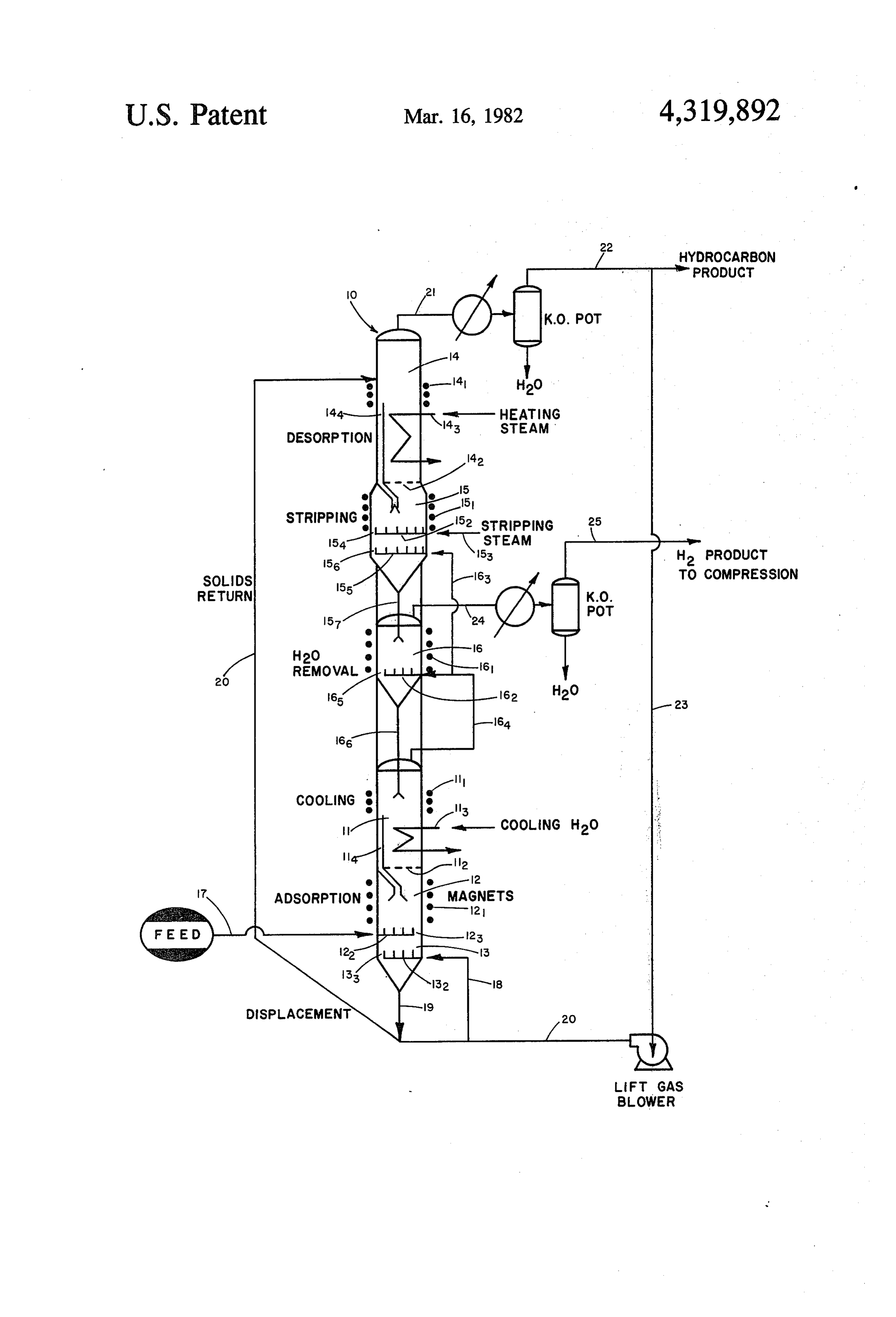
ping steam required in the hydrocarbon stripping zone In the drawing:
(d) by more effectively utilizing the steam injected into 55 The FIGURE depicts, by means of a simplified flow the zone. diagram, a preferred magnetically stabilized bed tem Additionally the steam displacement stage prevents perature swing hydrogen recovery process adsorption any residual gaseous hydrocarbon left in the interstices desorption unit 10 as used in the recovery of hydrogen or pores of the adsorbent particles from contaminating from a gaseous admixture of hydrogen and hydrocar the purified hydrogen which is recovered downstream 60 bons from refinery effluents. Cyclone separators, bed in a more advanced stage of the operation. levels, compressors, pumps, and other auxiliary equip In the second stage of the water removal/cooling ment for the most part have been omitted from the Zone, i.e., the evaporative stage cooling stage, the adsor drawing for simplification.
bent particles are countercurrently contacted with Referring generally to the figure it will first be ob product hydrogen which has been injected into the 65 served that the unit 10 necessarily includes a sorption or bottom of the stage at a rate sufficient to strip essentially adsorption portion and a desorption portion, the ad all the water from the adsorbent particles. The removal sorption portion of the unit in this instance being lo of water evaporatively cools the adsorbent particles cated at, or near, the bottom of the vessel while the 6 latter is located at the top of the vessel. The (1) sorption of the bed via use of a magnetic field coil 11 surround or adsorption portion of the unit 10, on the one hand, ing the upper vessel exterior, above the bed surface. thus includes an upper cooling section 11, an adsorption The cooled adsorbent solids are introduced into the section 12 to the lower side of which the hydrogen-con adsorption section 12 via overflow through weir 114, taining feed gas or vapor is introduced, and a hydrogen and the downwardly flowing adsorbent solids are re displacement section 13. The (2) desorber or desorption plenished within the bed of the cooling section 11 by portion of the unit 10, on the other hand, includes a freshly regenerated adsorbent solids from water re desorption section 14, a stripping section 15, and a moval section 16 of the desorption portion of the unit. water removal section 16. In such unit 10 hydrocarbons Solids leaving the adsorption section 12 are passed are adsorbed from an upwardly flowing hydrogen/hy 10 downwardly via overflow of the distributor 122 as via drocarbon admixture by downwardly moving adsor passage 123, the solids flowing into hydrogen displace bent solids, within the adsorption portion of the unit, ment section 13.
adsorbed hydrogen is displaced and the hydrogen The hydrogen displacement section 13 constitutes a denuded, hydrocarbon-enriched adsorbent solids then key and novel feature of the process. Recycled hydro transported to the desorption portion of the unit for the 15 carbon gas is introduced into this section to displace extraction and recovery of the hydrocarbons to regen hydrogen from the interstices and pores of the spent erate the adsorbent solids, and produce a hydrogen adsorbent solids. Unavoidably, the adsorbent solids product. It is quite evident also that (1) the sorption or which are transferred from the adsorption section 12 adsorption portion and (2) desorber or desorption por thus contain a relatively large amount of hydrogen both tion of the unit can be alternately located one with 20 within the interstitical volume, or volume between the respect to the other, or the operations conducted in adsorbent solids particles, and the pore volume of the separate vessels. A convenient alternate unit might thus adsorbent solids, and to the extent that hydrogen is comprise (1) a first vessel which contains an upper cool present in the adsorbent solids passed to the desorption ing section 11, an intermediate level adsorption section section 14 it is wasted through contamination with gases 12 to the lower portion of which the gaseous feed is 25 which exit the system in regeneration of the adsorbent introduced, and a lower displacement section 13, and solids. Thus, if the adsorbent solids were removed di (2) a second vessel which contains an upper desorption rectly to the desorption section 14, then this hydrogen section 14, intermediate stripping section 15 and water would be stripped off by the hydrocarbons and exit the removal section 16, in which unit the process gas, i.e., unit with the desorber gas, thereby reducing hydrogen hydrogen or hydrocarbon, is used to lift the solids to the 30 recovery. In the operation of the displacement section top of each vessel, respectively. 13 therefore, a portion of the hydrocarbon product The operation and function of each of these sections, substantially equal in volume to the volume of hydro beginning with the adsorption or "sorber side' of the gen and residual feed gas components contained in the unit is as follows: voids and pore volume of the adsorbent solids is added The adsorption section 12 is operated adiabatically, 35 via line 18 through distributor 132 to substantially to and contains a magnetically stabilized bed of adsorbent tally displace, or displace to the full extent possible, the solids. It is further characterized in that the bed is de hydrogen contained within the voids and pore volume scending, or downwardly moving, and the bed of par of the adsorbent solids such that the adsorbent solids ticulate adsorbent solids are preferably of a ferromag which are overflowed or passed through distributor 13 netic activated carbon or molecular sieve composite. 40 as via passage 133 and picked up via the hydrocarbon lift Thus, the bed is stably fluidized by ascending gases gas as they exit the displacement section 13 via line 19 while acted upon by a magnetic field produced by a are substantially devoid of hydrogen.
coiled magnet 121 externally concentrically fitted about In a preferred operation of the hydrogen displace the wall of the vessel, the gases being constituted in part ment section 13, the entering adsorbent solids particles by the gaseous feed which is introduced into the bottom 45 are moved in plug flow, without application of a stabi of the adsorption section 12 through distributor 122, via lizing magnetic field, countercurrent to the ascending line 17, and hydrocarbon stripping gas which flows stream of recycle hydrocarbon introduced via line 18. upwardly from hydrocarbon displacement section 13. The adsorbent solids particles are thus purged of hydro Gas of relatively low hydrogen content thus enters the gen and gradually slump or move closer together to aid bottom of this section and flows countercurrent to the 50 in the displacement of hydrogen. By careful adjustment slowly descending stably fluidized adsorbent solids. As of the flow of hydrocarbon recycle stream a boundry is the gas flows upwardly through the bed of the adsorp formed within this section below which the down tion section 12, hydrocarbons, and other non-hydrogen wardly moving solids contain essentially no hydrogen. components are adsorbed on the sorbent solids. Adsorp In another preferred operation, the adsorbent solids tion of the hydrocarbons produces heat, and accord 55 particles of the stripping section 13 can be stabilized as ingly the solids which are introduced into the adsorp a bed by the application of a magnetic field to aid in the tion section 12 are cooled by a predetermined amount transport and movement of the particles from the sec within the cooling section 11 prior to their introduction tion. In this embodiment the elimination of hydrogen into adsorption section 12. from the purged solids is aided by establishing a temper Cooling of the adsorbent solids within cooling sec 60 ature gradient between the bottom and the top of the tion 11, prior to their introduction into adsorption sec bed. Suitably low level heat from a suitable source can tion 12, is accomplished by maintaining the particulate be exchanged with the top of the bed, and high level adsorbent solids in a fluidized state to achieve good heat (i.e., higher temperature) heat from a suitable source transfer, while cooling. The bed of stably fluidized ad can be exchanged with the bottom of the downwardly Sorbent Solids, which rests atop grid 112, is cooled, e.g., 65 moving, stably fluidized bed. via use of a heat transfer coil 113 located into the vessel In the first portion of the desorption cycle the adsor through which cooling water is passed during the oper bent solids are heated in a fluidized bed to desorption ation. A filter can be provided, if desired, above the top temperature to desorb some hydrocarbons, residual 7 hydrocarbons are removed in the steam stripping sec the adsorbed solids particles. The dry, regenerated ad tion 15; and then the water is removed from the adsor sorbent solids particles are then flowed via passageway bent solids by treatment with hydrogen. 165 of distributor 162, and dipleg 166 into the cooling Adsorbent solids nearly saturated or saturated with section 11 of the adsorption portion of the unit. Wet hydrocarbons, but devoid or substantially devoid of 5 gases from the water displacement section 16 is passed hydrogen are picked up on discharge from line 19, lifted via line 24 through a heat exchanger into a water knock and fed via solids return line 20 into desorption section out pot, and the hydrogen product withdrawn via line 14. The bed of adsorbent solids contained therein is 25.
fluidized, to improve heat transfer between the adsor The following is further exemplary of the invention. bent solids; the bed being fluidized by wet gases which 10 EXAMPLE ascend through grid 142 atop which the bed rests. Suit ably, a filter is maintained above the bed to suppress the For convenience, reference is again made to the Fig escape of solids from the top of the bed. Thus, a mag ure, and to the Table given below. The bracketed num netic field can be maintained well above the top level of bers refer to the Table, the Table giving the composi the bed, e.g., by use of magnetic coil 141. The bed is 15 tion, temperature, flow rates, etc. at different locations heated by an internal heat exchange coil 143 through within the process.
which steam is passed. The heating of the adsorbent A feed stream, 1), consisting of 75% H2 and 25% solids forces the interstitial gas out of the solids by de hydrocarbons at 200 psig is introduced into the adia sorption and thermal expansion, and the wet ascending batic adsorption zone 12 where it is countercurrently gas introduced into the desorption section 14 aids in 20 contacted with the descending particulate carbon solids displacing the hydrocarbons. The desorbed hydrocar (containing 30 wt.% stainless steel powder as an inclu bons exits the desorption section 14 with the wet gas via sion). The rate of solids movement is approximately line 21. The exit gas is heat exchanged, fed into a knock 1.70X 10.5 lbs/hr. The temperature of the carbon solids out pot to eliminate water, the uncondensed gas recov increases as adsorption occurs such that at the feed inlet ered as a hydrocarbon product from line 22, while a 25 point, the solids are at 265” F. and contain 7.1 lb. hy portion thereof is recycled via line 23,20 for use as an drocarbon/100 lbs. carbon. As the solids continue to fall adsorbent solids liftgas, and hydrogen displacement gas below the feed inlet point, they carry feed gas with in hydrogen displacement section 13. The partially re them in the interstices between particles and in the generated adsorbent solids are passed via overflow weir pores within the particles; and the feed gas contains a 144 to steam stripping section 15 for further removal of 30 significant amount of hydrogen which could not be hydrocarbons. . -recovered if it were allowed to enter the desorption The partially regenerated adsorbent solids, trans section. The feed gas, accordingly, is displaced with a ferred into the steam stripping section 15 from desorp rising recycle gas stream 8 containing 3.2% H2 in tion section 14, are introduced into a bed fluidized by jected into zone 13 via line 18. The recycle stream, 8), gases from below passed through distributor 152. The 35 is added at a rate exactly equal to the downward flow of fluidized bed is acted upon by a stabilizing magnetic feed gas being carried by the descending solids. Because field applied, e.g., via use of an externally mounted of the higher hydrocarbon partial pressure in the dis magnetic coil 151. Steam is injected into the bed placement zone, additional hydrocarbon is adsorbed through line 153, the steam virtually purging the pores such that as the carbon leaves the bottom of the vessel of the adsorbent solids of hydrocarbons, and heating the 40 via line 19, the temperature is 290 F. and the hydrocar hydrogen denuded adsorbent solids. The heated, hydro bon loading is 9.6 lb. hydrocarbon/100 lbs. of carbon. gen denuded adsorbent solids overflow the distributor The solids leaving the bottom of the column are 152, leaving via passage 154 to enter into the first of a transported via line 20 to the desorption section at the series of staged water removal zones, in this instance top of the column by a hydrocarbon recycle gas stream two staged zones. In the first zone the steam is displaced 45 7). The solids are heated to a desorption temperature of from the interstices and pores of the adsorbent solids 390 F. in the fluid bed of zone 14. Heat exchange with particles with hydrogen to effect better heat utilization, condensing 600 psig steam, stream (15), supplies the and suppress possible contamination of the product necessary heat. The fluidizing gas is supplied from the hydrogen with hydrocarbons. stripping section immediately below the fluid bed; the The wet hydrocarbon denuded adsorbent solids pass 50 fluidizing gas consisting of stripping steam introduced distributor 152, thus pouring into a downwardly moving by line 153 and the hydrocarbon desorbed in the strip slumped, or falling bed of said material. The bed formed ping section. Some desorption occurs in the fluid bed is contacted with hydrogen introduced to distributor desorption section such that the carbon leaving the fluid 155 via line 163. A major portion of the steam is therein desorption section, stream S-9), contains 5.2 lbs. hy displaced from the interstices and pores of the adsorbent 55 drocarbon/100 lbs. carbon, and it contains 1.2 lbs. of solids, this suppressing contamination of the product adsorbed water/100 lbs. carbon.
hydrogen as would occur if most of the hydrocarbons Most of the residual hydrocarbon remaining on the were transferred with the adsorbent solids to the second carbon leaving the fluid bed is removed in the stripping water removal stage. The partially dried adsorbent zone. In the stripping zone, the descending solids are solids overflow the bed via passageway 156 of distribu- 60 countercurrently contacted with 200 psig stripping tor 155 to enter via dipleg 157 the second water displace steam introduced via line 153, stream 5), which has ment, or water removal zone, viz., water removal sec been directly injected into the bed. A portion of the tion 16. In this second zone, the partially dried adsor steam is adsorbed on the carbon. The heat of adsorption bent solids are fluidized by hydrogen injected through of the water is mostly offset by the heat of desorption of distributor 162 from line 164, and the fluidized bed is 65 the hydrocarbon such that the temperature of the solids stabilized by a magnetic field generated via an exter leaving the adiabatic stripping vessel via line 157 is 400 nally mounted magnetic coil 161. The injected hydro F. These solids contain 1.1 lbs. hydrocarbon/100 lbs. gen removes essentially all of the residual water from carbon and 3.8 lbs. H2O/100 lbs. of carbon.
Page 8scan →
The solid, as it passes the steam injection point carries TABLE-continued steam with it in the interstices, and in the pores. The Mole % steam in the interstices and pores would not be utilized H2 - 97.2 M M-- if it were allowed to be carried downward with the Hydrocarbon M- w-M 0.4 ma M solids. Consequently, the steam is displaced with H2, H2O - - 2.4 M 100 introduced via line 163, stream 3). As in the adsorber LbHr Mole/Hr mem M 837 - - 394 displacement section, the hydrogen stream 3), is added Carbon (1 x 10) 1.2 1.2 - 1.2 1.2 - to exactly balance the downward flow of steam being Stainless Steel (1 x 10) 0.5 0.5 - 5 w-m carried in descending voids between particles and in the Steam (1 x 10) mm M. n- 7. pores of the particles. 10 Wt. 2 on Carbon
Hydrocarbon 0.4 0.4 MM 7. 9.6 m
The carbon leaving the stripping zone contains ad H2O 0.3 0.3 - -- -mm -M sorbed water which is removed in the adiabatic water Temperature, F. 300 200 200 265 290 486 removal zone 16. In this zone, a hydrogen stream 2 from cooling zone 11, is countercurrently contacted The present process has its greatest utility in the sepa with the carbon to strip the water from the carbon. The 15 ration and recovery of hydrogen from hydrogen in removal of water evaporatively cools the solid from admixture with hydrocarbons, or hydrocarbons con 400 F. to 300' F. The countercurrent contact with H2 in the evaporative cooler also strips additional hydro taminated with various acidic, polar, or non-polar com carbon from the carbon such that the solids leaving the high purity can be hydrocarbons.
pounds other than readily
Hydrogen of selected, recovered from hydrogen gas evaporative cooler via dipleg 166, stream S-11 contain 0.4 lbs. hydrocarbon/100 lbs. carbon and 0.3 lb. of admixed with up to about 50 percent, or higher hydro
H2O/100 lbs. of carbon. The hydrocarbon which is carbons, suitably from about 10 percent to about 50 removed in the evaporative cooler leaves with the percent hydrocarbons, with additional contaminants product H2, stream 4, resulting in a H2 product of such as carbon monoxide, carbon dioxide, hydrogen sulfide, ammonia, sulfur dioxide, hydrogen cyanide, 96.4% purity. Lower or higher purity product could be 25 mercaptains obtained by adjusting the steam stripping rate stream and the like.
5, to leave either more or less hydrocarbon on the orThe adsorbent solids can be employed as admixtures composites which contain a ferromagnetic or ferri carbon leaving the stripper.
Further cooling of the solid, from 300 F. to 200 F., 30 magnetic component or substance. Exemplary of such ferromagnetic and ferrimagnetic substances are mag is effected in fluid bed cooler 11. Heat exchange with netic Fe3O4, y-iron oxide (Fe2O4), ferrites of the form cooling water stream at 1232 gal/min., is used to cool the solids. H2 product gas flows upward from the ad MO.Fe2O3, wherein M is a metal or mixture of metals sorber, stream G-12, thru a grid and provides the fluid such as iron,Zn, Mn, Cu, etc.; ferromagnetic elements in ization. After being cooled to 200 F., the solids IS-12 35 cluding ferromagnetic nickel, cobalt and gadolinium, alloys of elements, etc. The adsorbent solids are re-enter the adsorber.
Table
chosen to suit the particular feed and the contaminent substance, or substances, that is to be removed from the
Stream feed. Inorganic, organic or high molecular weight inor 2 3 4. 5 ganic or organic adsorbents may be used.
MSCFAD O 7.6 0.96 7.7 4.45 Exemplary of adsorbent solids are activated carbons, Mole % treated activated carbons, molecular-sieving carbon;
Hydrocarbon selected artificially synthesized zeolites, such as those
H2O w 2.4 2.4 - 100 having some particular synthesized zeolites, such as Mole/Hr O96 837 106 844 488 those having some particular ratio of principal compo LbHr 45 nents identified as: “Type A'; “Type L”; “Type X'; Carbon
Stainless Steel m
"Type Y”; “Type ZSM'; mordenite; faujasite; erionite;
Stean w m M - 8.8 x 10 and the like; those zeolites which have particular silica Wt. 26 on Carbon alumina ratio and those in which the original sodium Hydrocarbon mm. w www. www. cations are exchanged to other cations; selected silica H2O -ww. ww. m 50 gels such as those having some particular relative com Temperature, F. 85 200 200 110 382 ponents of silica, alumina and ferric oxides, those which
Stream have particular steric properties as the average pore 6 7 8 S-9 S-10 diameter, specific surface area, pore volume and others; MSCFAD 2.3 3.5 2.1 - www. selected activated aluminas such as those having partic Mole % 55 ular components of aluminum oxide and water, those H2 3.2 3.2 3.2 - o hydrated forms, some particular crystal forms, those Hydrocarbon 96.8 96.8 96.8 . a
H2O w m w Mw w which have a particular structure; activated clay or
MoleAHr 252 383 226 - orm selected acid clays such as montmorillonite in which Lb/Hr case base is exchange holloysite or attapulgite. Other Carbon - - - 1.2 x 10 1.2 x 10 60 suitable zeolites, and their method of preparation, are Stainless Steel - - - 0.5 x 10 0.5 x 10
Steam MM m m w given, e.g., in U.S. Pat. Nos. 2,882,243; 2,882,244; Wt. 2 on Carbon 3,130,007; 3,410,808; 3,733,390; 3,827,968 and patents Hydrocarbon more
. mentioned therein, herein incorporated by reference.
Temperature, F. 110 17 17 390 400 Other adsorbents suitale in the practice of the inven 65 tion include cation-exchange resins with exchange
Stream groups of benzene sulfonic acid, carboxylic acid, phos
S-1 S-12 G-12 S-13 S.14 15 phoric acid; strongly or weakly basic anion-exchange MSCFAD M ww. 7.6 m M 3.6 resins; high molecular weight particles of styrene-divi 9 nylbenzene copolymer, or its halomethylated, or cyano spray drying, etc. The magnetizable component may ethylated polymers; acrylonitrile copolymers; high mo also be composited with the adsorbent by impregnation, lecular weight compounds having several functional cogelling, coprecipitation, etc. groups such as cyano, cyanomethyl, chloromethyl, The bed particles (composites or admixtures) will thioether, sulfone, isocyanate, thiocyante, thiourea, typically have an average particle diameter ranging allyl, acetyl-acetone, aldehyde, ketone, aliphatic, anhy from about 50 to about 1500 microns, preferably from dride, ester, halogen, nitro and others. about 100 to about 1000 microns, and more preferably Preferred adsorbents for achieving high adsorption from about 175 to about 850 microns. The particles may desorption rates are activated carbons, molecular-siev be of any shape, e.g., spherical, irregular shaped or ing carbon, synthetic zeolites and high molecular O elongated.
weight organic materials. These adsorbents generally The application of a magnetic field to the fluidized, show a high adsorption exchange rate, due to their expanded or levitated particles containing the magnetiz chemical affinity for adsorption of various contami able particles in the adsorption or desorption zones in nants. Synthetic zeolites provide a particularly useful accordance with the invention is not limited to any class of inorganic adsorbents because the adsorption 15 specific method of producing the magnetic field. Con power of the molecules selected for adsorption onto ventional permanent magnets and/or electromagnets Zeolites can easily be altered by exchanging sodium ions can be employed to provide the magnetic field used in which usually come from the original production steps the practice of the present invention. The positioning of into some other cations to change their crystal structure the magnets will, of course, vary with the solids used, or electron configurations to the desired forms. Usually 20 degree of fluidization required and the effects desired. Group I metal ions such as lithium, potassium, rubid Typically a toroidally shaped electromagnet is en ium, cesium; silver, copper; Group II metal ions such as ployed to surround at least a portion of the fluidized bed beryllium, magnesium, calcium, strontium, barium, as this provides the most uniform magnetic field and zinc, cadmium, mercury; titanium, Vanadium, chro consequently the best stability throughout the bed. The mium, nickel, cobalt, iron, manganese; rare earth met 25 electromagnets may be energized by alternating or di als; uranium; and lead cations or their mixtures are used rect current, although direct current energized mag to replace sodium ions originally contained in the Zeo netic fields are preferred. Such electromagnets when lites. The more effective sets of cations are: potassium powered by direct current with the use of a rheostat are and lithium; potassium and calcium; potassium and cad particularly desirable for applying magnetic field to the mium, potassium and iron; potassium and nickel; potas bed particles and to provide an excellent method of sium and cobalt; potassium and barium; potassium and stabilizing the fluidization of the bed particles in re magnesium; calcium and magnesium; calcium and man sponse to the flow of the fluidizing medium. ganese; lithium and manganese; barium and sodium; The magnet can be of any size, strength or shape and barium and lead; iron and uranium; and others. The can be placed above or below the bed to achieve special synthetic zeolite adsorbent solids will typically contain 35 effects. The magnets employed can be placed within or 75–98% of the zeolite component and 2-25% of a ma without the vessel and may be employed as an integral trix, (e.g., binder), component. The zeolites will usually portion of the vessel structure itself. The process is not be exchanged with sufficient cations to reduce the so limited to any particular vessel material and it can be dium level of the zeolite to less than 5 wt.%, preferably readily adapted for use in contacting vessels currently less than 1 wt.%. Reference in this regard is made to the employed by industry.
following U.S. Pat. Nos.: 3,140,249; 3,140,251; 3,140,252 The amount of magnetic field to be applied to the and 3,140,253, which are incorporated herein by refer fluidized solids in the contacting zones (adsorption and eCe. desorption zones) will, of course, depend on the desired When the magnetizable component is admixed with magnetization for the magnetizable particles and the nonmagnetic adsorbent particles, it is preferred that the 45 amount of stabilization desired. Particles having rela volume fraction of the magnetizable component exceed tively weak magnetic properties, e.g., cobalt, nickel, 25 volume percent, more preferably it should exceed 50 etc., will require the application of a stronger magnetic volume percent, and more preferably more than 60 field than particulate solids having strong ferromagnetic volume percent, to obtain the greatest bed stability at properties, e.g., iron, to achieve similar stabilization the lowest applied magnetic field strength. 50 effects. The size and shape of the solids will also obvi In case of a composite of the magnetizable compo ously have an effect on the strength of the magnetic nent and the adsorbent, the ferromagnetic and/or ferri field to be employed. However, since the strength of the magnetic material will comprise from about 1 to about field produced by an electromagnet can be adjusted by 25 percent, preferably from about 5 to about 15 percent, adjusting the field strength of the electromagnet the based on the total volume of the composite adsorbent. 55 field strength employed can be readily adjusted to In any event, the composite should have a magnetiza achieve the desired degree of stabilization for the partic tion of at least 50 gauss, preferably greater than 250 ular system employed. Specific methods of applying the gauSS. magnetic field are also described in U.S. Pat. Nos. The composites of the magnetizable component and 3,440,731; 3,439,899; 4,115,927 and 4,143,469; British the adsorbent may be prepared as follows: the magnetic Pat. No. 1,148,513 and in the published literature, e.g., component such as 400 Series stainless steel, particles M. V. Filippov, Applied Magnetohydrodyanamics, and the adsorbent, e.g., the Zeolite sieve, are admixed Trudy Instituta Fizika Akad. Nauk, Latviiskoi SSR with a base (matrix or binder) for the adsorbent and a 12:215-236 (1960); Ivanov et al, Kinet, Kayel, 11 relatively homogeneous gel is formed. The adsorbent (5):1214-1219 (1970); Ivanov et al., Zhurnal Prikladnoi base may be comprised of, for example, silica, alumina 65 Khimi, 45:248-252 (1972); and R. E. Rosensweig, Sci or silica-alumina. The gel is then dried, calcined and ence, 204:57-60 (1979), which are incorporated herein sized. Suitable techniques for sizing and shaping the by reference. The most preferred applied magnetic field composite adsorbent are extrusion, pilling, beading, will be a uniform magnetic field such as described in
Page 10scan →
U.S. Pat. No. 4,115,927. Typically, the empty vessel (d) in said stripping zone, the residual hydrocarbons applied magnetic field, as taught in U.S. Pat. No. containing particulate adsorbent Solids are formed 4,115,927, will range from about 50 to about 1500 Oer as a moving, fluidized bed of said solids, and said steds, preferably from about 100 to about 600 oersteds bed magnetically stabilized to suppress the gross and more preferably from about 125 to about 400 oer circulation of adsorbent solids within said bed, steds. while said bed is contacted countercurrently said The feed from a variety of sources can be used to bed with a stripping agent to desorb, and substan supply hydrogen, e.g., catalytic cracking off-gas, gas tially displace the residual hydrocarbons. from catalytic reforming and the like. 3. In an adsorption process for the recovery of hydro It is apparent that the present invention is subject to 10 gen from a vapor or gas feed containing hydrogen in various modifications and changes without departing admixture with one or more component hydrocarbons, the spirit and scope thereof. alone or in admixture with non-hydrocarbon compo Having described the invention, what is claimed is: nents, wherein particulate adsorbent solids are circu 1. In an adsorption process for the recovery of hydro lated between an adsorption zone for contact with said gen from a vapor or gas feed containing hydrogen in 15 feed at relatively low temperature to selectively adsorb admixture with one or more component hydrocarbons, hydrocarbons and thereby concentrate the hydrogen alone or in admixture with non-hydrocarbon compo within the off gas from said adsorption zone for recov ments, wherein particulate adsorbent solids are circu ery, the particulate adsorbent solids which selectively lated between an adsorption zone for contact with said 20 adsorb hydrocarbons are transported to a desorption feed at relatively low temperature to selectively adsorb zone operated at sufficient temperature above that of hydrocarbons and thereby concentrate the hydrogen the adsorption zone to desorb hydrocarbon and regen within the off gas from said adsorption zone for recov erate the said particulate adsorbent solids, the regener ery, the particulate adsorbent solids which selectively cled ated particulate adsorbent solids are cooled and recy adsorb hydrocarbon components are transported to a 25 thetoimprovement said adsorption zone comprising desorption zone operated at sufficient temperature (a) contacting countercurrently said feed in said ad above that of the adsorption zone to desorb hydrocar sorption zone with a downwardly moving, fluid bon and regenerate the said particulate adsorbent solids, ized bed of the particulate adsorbent solids pro the regenerated particulate adsorbent solids are cooled vided with a magnetic component, magnetically and recycled to said adsorption zone 30 stabilizing said bed to suppress the gross circulation the improvement comprising of adsorbent solids within said bed, while adsorb (a) contacting countercurrently said feed in said ad ing hydrocarbons from said feed on said bed, with sorption zone with a downwardly moving, fluid drawing from said adsorption zone a hydrocarbon ized bed of the particulate adsorbent solids pro denuded gas stream of higher hydrogen content vided with a magnetic component, magnetically 35 than that contained in the feed entering said mag stabilizing said bed to suppress the gross circulation netically stabilized adsorption zone, withdrawing of adsorbent solids within said bed, while adsorb hydrocarbon enriched, hydrogen-containing par ing hydrocarbons from said feed on said bed, with ticulate adsorbent solids from said magnetically drawing from said adsorption zone a hydrocarbon stabilized adsorption zone and passing same to a denuded gas stream of higher hydrogen content 40 hydrogen displacement zone, than that contained in the feed entering said mag (b) contacting countercurrently said hydrocarbon netically stabilized adsorption zone, withdrawing enriched, hydrogen-containing particulate adsor hydrocarbon enriched, hydrogen-containing par bent solids in said hydrogen displacement zone by ticulate adsorbent solids from said magnetically passing same in plug flow and contacting same stabilized adsorption zone and passing same to a 45 with a hydrocarbon gas sufficient to substantially hydrogen displacement zone, and then displace hydrogen, passing the displaced hydrogen (b) contacting countercurrently said hydrocarbon into the adsorption zone, and removing the hydro enriched, hydrogen containing particulate adsor gen-denuded, hydrocarbon-containing particulate bent solids in said hydrogen displacement zone by adsorbent solids from said hydrogen displacement passing Same in plug flow and contacting same 50 Zone and transporting same to the desorption zone. with a hydrocarbon gas sufficient to substantially (c) heating in the desorption zone a fluidized bed of displace hydrogen, passing the displaced hydrogen said hydrogen-denuded, hydrocarbon-containing into the adsorption zone, and removing the hydro particulate solids at temperature sufficient to de gen denuded, hydrocarbon-containing particulate sorb hydrocarbons from said particulate solids, adsorbent solids from said hydrogen displacement 55 removing hydrocarbons from said zone, and pass Zone and transporting same to the desorption zone. ing particulate adsorbent solids containing at least 2. The process of claim 1 further characterized in that residual amounts of hydrocarbons to a hydrogen the hydrogen denuded, hydrocarbon-containing partic stripping zone, and ulate adsorbent solids are transported to the desorption (d) in said hydrogen stripping zone, contacting coun Zone, and 60 ter-currently with hydrogen, the residual hydro (c) in said desorption zone, a fluidized bed of said carbons-containing particulate adsorbent solids as a hydrogen denuded, hydrocarbon-containing par moving, fluidized bed, while magnetically stabiliz ticulate solids is formed and heated at temperature ing said bed to suppress the gross circulation of sufficient to desorb hydrocarbons from said partic adsorbent solids within said bed, to desorb, and ulate solids, hydrocarbons are removed from said 65 Substantially displace the residual hydrocarbons Zone, and particulate adsorbent solids containing at with hydrogen. - least residual amounts of hydrocarbons are passed 4. The process of claim 3 wherein the temperature of to a stripping zone, and the adsorption zone (a) ranges from about 130 F. to 11 about 250 F., the temperature at the top of the hydro about 450 F. above the temperature at the top of the carbon displacement zone (b) ranges from about 10 F. bed.
to about 100 F. higher than the temperature of said 8. The process of claims 1, 2 or 3 wherein the adsor adsorption zone, the temperature of the desorption zone 5 bent from solids entering the hydrogen displacement zone (b) said adsorption zone (a) are fluidized as a bed, and (c) ranges from about 350 F. to about 450 F., and the stabilized by an applied magnetic field, and a gradient hydrocarbon stripping zone (d) is operated at a temper temperature is applied across said bed, the temperature ature ranging from about 350 F. to about 450 F. at the bottom of said bed ranging about 60 F. to about 5. The process of claims 1, 2 or 3 wherein the temper 450 F. above that at the top of said bed. ature of the adsorption zone (a) ranges from about 40 10 9. The process of claims 2 or 3 wherein the tempera F. to about 300' F., and the temperature of the hydro ture of the desorption zone (c) ranges from about 300 F. to about 600 F., and the hydrocarbon stripping zone gen displacement zone (b) ranges about 10 F, to about (d) 150 F. higher than the temperature of said adsorption is operated at a temperature ranging from about 300
ZOle. 15 10. The process of claims, 1, 2 or 3 wherein said ad 6. The process of claims 1, 2 or 3 wherein the adsor sorption particles and magnetizable component have an bent solids entering the hydrogen displacement zone (b) average mean particle diameter ranging from 50 to from said adsorption zone (a) are fluidized, and stabi about 1500 microns.
lized by an applied magnetic field. 11. The process of claims 1, 2 or 3 wherein said adsor 7. The process of claims 1, 2 or 3 wherein the adsor bent particles and magnetizable component are compos bent solids entering the hydrogen displacement zone (b) ited.
12. The process of claims 1, 2 or 3 wherein said adsor from said adsorption zone (a) are fluidized, and stabi bent lized by an applied magnetic field, and the bed operated vatedparticles include activated carbon, treated acti carbon or molecular-sieving carbon particles.
at a bottom temperature ranging from about 60 F. to 25 k k is k sk
Provenance
- Collection
- Patents citing this work
- Pages
- 11
- Method
- pdftotext (the PDF's own text layer) + pdftoppm 300dpi page scans
- Patent office record
- patents.google.com →
- Source
- Google Patents citing-documents table
- Assignee
- Exxon Research & Engineering Co.
- Published
- 1982-03-16
- Transcribed from
- patentimages.storage.googleapis.com →