

patent · US4326501A
Solar furnace
27 April 1982
Text
Drawings
Page 1drawing sheetscan →
Page 2scan →
United States Patent (19)
Jardin
(54). solar furnace
76 Inventor: Albert C. Jardin, 170 Old Mill Blvd.,
51 Int. Cl.................................................. F24J 3/02 52 U.S. Cl. .................................... 126/430; 126/400;
4,059,226 11/1977 Atkinson ............................. 126/400
4,088,266 5/1978 Keyes .................................. 126/400
4,094,302 6/1978 Rohr ................................... 126/4OO 4,111,189 9/1978 Dizon .................................. 126/400 4,141,339 2/1979 Weinstein ............................ 126/449 4,169,461 10/1979 Haug et al. .......................... 126/400 4,187,904 2/1980 Kuhnlein ............................. 126/400 4,205,662 6/1980 Rhodes ................................ 126A49 4,241,782 12/1980 Schoenfelder ...................... 126/400 Primary Examiner-Daniel J. O'Connor
Attorney, Agent, or Firm-Max Schwartz
The invention comprises a single unit which serves as the solar collector, heat storage area, and the heat ex changer. A generally rectangular tank is provided with suitably heavy insulated walls at the bottom, ends and rear. One side, facing the sun is open and the opening extends into a portion of the top. The top is provided with a thickly insulated cover. The open side is pro vided with a corrugated surface, the preferred angle being the latitude plus 10'. The water is carried through suitable tubing which enters the tank through one end wall. The tubing is reentrantly bent in the tank to pro vide a plurality of lengths (4 shown) and then out through the same end wall but below the entrance. The tank is then filled with a suitable material having good heat storage and heat exchange properties. The best material is an eutectic salt having extremely high heat absorption and storage ability in direct contact with the container wall, which is designed to absorb heat radia tion, and in direct contact with the tubing to transfer the heat to the water passing through. Other substances, such as concrete, can also be used. The corrugated side is covered with an insulating glass or transparent plastic twin-walled sheet mounted at the front. The unit is attached to the water supply through the tubing extend ing at one side, the conventional water supply pressure being sufficient to operate the unit. The unit is placed on the ground adjacent the building. The unit is modular and the effects can be increased by adding units in line and hooking them up in series or parallel as desired. The system lends itself to the use of much smaller units hooked together in banks for easier handling.
2 Claims, 6 Drawing Figures
Page 3drawing sheetscan →
Page 4scan →
SOLAR FURNACE the tube passes through the end wall 12 and is bent to form lengths 26 (4 shown) with the heated water pass ing out at the end 28. The ends 26 and 28 are directly
BACKGROUND OF THE INVENTION connected with the building's water system, since the Solar units are now becoming popular for heating -unit operates on the normal water supply pressure. water and buildings. However, these are costly to man The tank 10 is now filled with a suitable heat storage ufacture and to install. Most of these units are mounted material. The preferred material is eutectic salts. These on the roof and act as solar collectors. The heat col salts store the heat from the collector side of the tank. lected must then be stored and some means of heat They also act as heat transfer mediums to heat the water exchange must be provided. The system must be pro 10 passing through the tubes 22. The salts are added after vided with differential thermostats, controls, pressure the tank is placed in its permanent site by heating to the reducing controls and other types of controls, all com melting point (80) and pouring into the tank and plex and costly. around the tubes 22. Other materials, such as concrete,
In operation, the solar rays strike the tank 10, particu
The present invention greatly reduces the complexity larly at the corrugations 20, to transfer the heat to the and cost by providing a single unit which serves as the material in the tank. The material, salts, concrete etc., is solar collector, heat storage area, and the heat, ex in contact with the tubing 22 which carries the water. changer. A steel or reinforced fiberglass tank is pro The water is thus heated as it passes through. The eutec vided with one wall which is corrugated at an angle that 20 tic salts or other material serves to store the heat and allows maximum insolation during December and Janu transfers it to the water. The unit is thus a self-con ary north of the equator. This is approximately equal to . tained, free standing solar heat collector, solar heat the latitude of installation plus 10. Tubing is used to storage, and solar heat exchanger in a single compact carry the cold water from the building supply through unit. This eliminates the need for differential thermo the tank and back to the building hot water system or 25 stats, controls heat exchangers, and pressure reducing heater. The tank is filled and surrounds the tubing with controls. It can be installed in old and new structures for eutectic salts or similar material or concrete for storing home or industrial hot water systems with two simple the heat from the collector side of the tank. These salts also act as heat transfer agents to heat the water passing areapipe connections. The unit thus uses the heat storage through the tubing. The salts are added to the tank after 30 itself as the solar collector and heat exchanger. The the tank has been placed in its permanent site by heating cost is comparatively small. The unit is modular in that one or more additional the salts to their melting point (80) and pouring into the tank. An insulated cover is then placed at the top. The units can be readily hooked up in series or parallel with a minimum of plumbing. By doubling the tubing in the unit is modular and several units can be attached in series or parallel if desired. 35 unit, it can be used for a low pressure hot water heating system using a single unit.
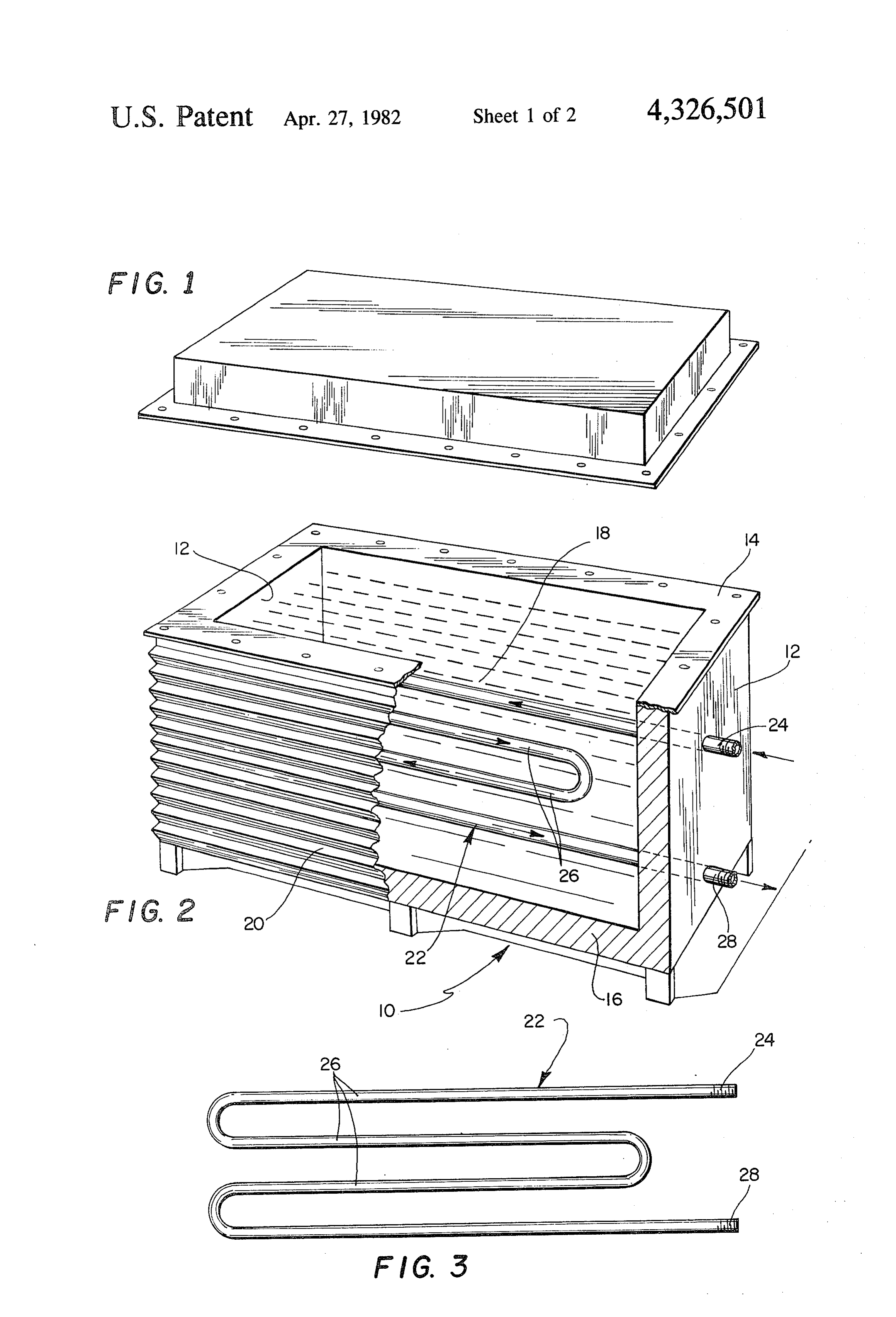
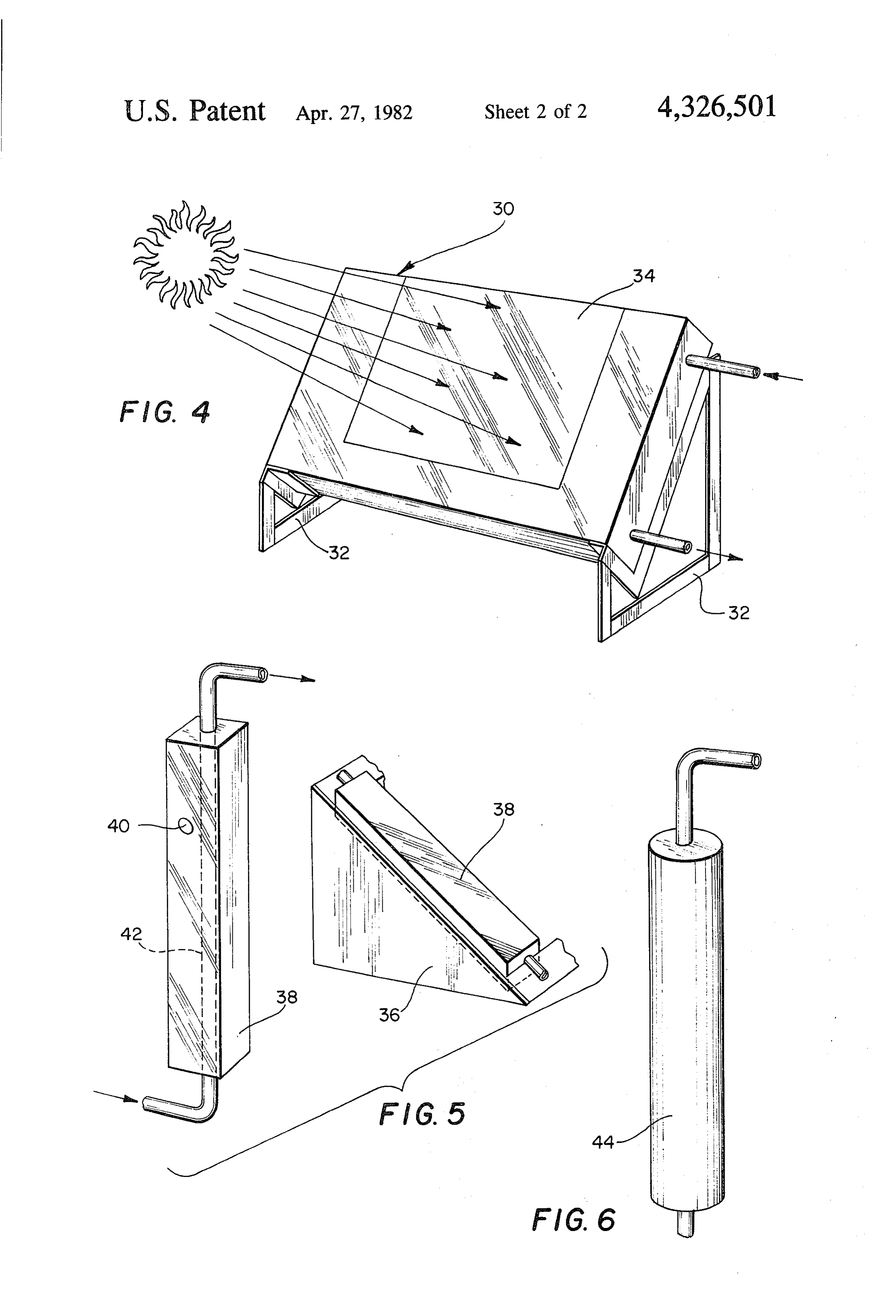
DESCRIPTION OF THE DRAWINGS The invention readily lends itself to variations. For In the drawings: example, FIG. 4 illustrates a method of cutting further FIG. is a perspective view of the cover for the unit costs and reducing the size. The tank 30 is flat and is of the present invention; 40 mounted on a cradle 32 at an angle of 45-52 facing the FIG. 2 is a perspective view, partly broken away, of sun. The flat steel plate 34 is covered by the insulating the solar furnace of the present invention; glass or plastic twin-wall (not shown). The interior is FIG. 3 is a side elevation of the tubing designed to made as in the main form, with the water carrying tub carry the water through the unit; ing and the eutectic salts or other material. FIG. 4 is a perspective view of a modified form of the 45 For ease of handling, the form shown in FIGS. 5 and invention; 6 may be used. However, the small size requires a plu FIG. 5 is a perspective view of a second modified rality of such units to be set up in a bank to equal the form of the invention; and capacity of the main form. Referring to FIG. 5, a rack FIG. 6 is a perspective view of a modified form of the 36 is designed to hold a plurality of units at an angle invention similar to the form shown in FIG. 5. 50 facing the sun, the latitude plus 10 for optimum results. The tank comprises an elongated rectangular steel hous
DESCRIPTION OF THE INVENTION ing 38 provided with an intermediate opening 40 Referring more in detail to the drawings, FIGS. 1, 2 through which the storage material such as the eutectic and 3 illustrate a solar furnace designed to be placed salts can be poured and the hole sealed. The water outside of a structure on the ground and connected to 55 passes through a straight tube passing through the tank the building's water system to provide hot water. and storage material. The elongated form providing The solar furnace comprises a steel or reinforced sufficient contact for heating. The pipes 42 are con glass fiber tank 10 having insulated end walls 12, a top nected in series to ensure sufficient heat from a plurality wall 4 and a front wall. The front wall and the top 14 of units. These units are cheap to build and easy to are cut out at 18 as shown in FIG. 2. The front is cov 60 handle.
ered with a corrugated wall 20, the angle of corrugation FIG. 6 illustrates a variation of the unit shown in being equal to the latitude plus 10.Insulating glass or FIG. 5. Here the tank 44 is similar to the tank 38 except transparent plastic twin-wall (not shown) is mounted in that it is round. The rest of the construction and mount front of the corrugated portion and secured to the tank ing is the same as in FIG. 5. The units shown in FIGS. while insulation 16 surrounds the tank and an insulated 65 5 and 6 can be easily stacked side by side and connected cover (FIG. 1) completes the insulation. to the water supply with a minimum of plumbing, be Water is circulated through the tank through the cause of the ease of handling and simplicity, these units tubing 22. The cold water enters at the upper end 24 as are fairly inexpensive to manufacture and set up.
Page 5scan →
I have thus provided a simple and inexpensive solar solar heat will be transmitted into and stored by said furnace which combines in a single unit a solar collec phase change material and transferred by said material tor, solar storage, and a heat exchanger. The unit is to said conduit to heat the water, wherein said heat cheap and efficient. Other advantages of the present storage and exchange materials comprise eutectic salt invention will be readily apparent to a person skilled in solutions such as calcium chloride hexahydrate or other the art. similar phase change material, wherein said tank is pro I claim: vided with thickly insulated walls, the front wall being 1. A solar furnace comprising a watertight tank, said cut away, said cut away portion being covered by a tank being capable of storing phase change material that corrugated plate adapted to receive the sun's rays, the changes from solid to semi-solid to liquid form, said 10 corrugations on said plate being at an angle of the sum tank being constructed of steel, reinforced glass fiber or of the latitude of installation plus 10 degrees, wherein similar material or combinations thereof, said tank being said tank is a rectangular tank, said tank being a self of a design to absorb solar radiation through its outer supporting structure and mounted outside the building front wall and into a phase change material which is in on the ground surface and facing the sun, wherein said direct and total contact with said front outer wall, said 15 conduit comprises tubing extending into said tank, said tank being also of a design to store and hold heat within tubing being bent to form a plurality of lengths of tubing itself through the use of said phase change material, said in said tank.
tank also containing a conduit through its side outer 2. A solar furnace as in claim 1, wherein said heat wall and into and through said phase change material storage and exchange material comprises concrete. for passing water into and out of said tank, whereby 20 s : k
Provenance
- Collection
- Patents citing this work
- Pages
- 5
- Method
- pdftotext (the PDF's own text layer) + pdftoppm 300dpi page scans
- Patent office record
- patents.google.com →
- Source
- Google Patents citing-documents table
- Assignee
- Jardin Albert C
- Published
- 1982-04-27
- Transcribed from
- patentimages.storage.googleapis.com →