

patent · US4329021A
Passive solar lighting system
11 May 1982
Text
Page 1scan →
United States Patent (19)
Bennett et al.
54) passive solar lighting system
75 Inventors: David J. Bennett, Minneapolis; David A. Eijadi, St. Paul, both of Minn.
(73) Assignee: Bather, Ringrose, Wolsfeld, Jarvis, Gardner, Inc., Minneapolis, Minn.
(52) U.S. C. .................................... 350/259; 126/440;
755,197 3/1904 Wadsworth. ... 350/260 1,101,001 6/1914 Willsie..................................... 84/69 1,130,871 3/1915 Willsie ................................. 126/422 3,125,091 3/1964 Sleeper, Jr. ......................... 126/426 3,915, 148 10/1975 Fletcher et al. .................... 126/422 4,056,094 11/1977 Rosenberg .......................... 126/440 4,069,812 1/1978 O'Neill ...... ... 182/89 4,108,540 8/1978 Anderson et al. ...................... 312/8 4,116,223 9/1978 Vasilantone ........................ 126/135
VZS 1 a
Other publications
"Lighting with Sunlight Using Sun Tracking Concen trators' Duguay and Edgar, Applied Optics, vol. 16, No.
"Transmission of 3-D Images by Means of Lens
Guides', Duguay and Aumiller, Applied Optics, vol. 18,
"Solar Electricity: The Hybrid System Approach",
Duguay, American Scientist, vol. 65, Jul.-Aug. 1977,
Primary Examiner-Richard A. Wintercorn
Attorney, Agent, or Firm-Merchant, Gould, Smith,
Edell, Welter & Schmidt
A passive solar lighting system is disclosed. A multi plyer lens (20) located within an aperture (12) in a build ing (10) increases the cone of light acceptance which would result in the absence of lens (20). Light passing through lens (20) is further refracted by lenses (22, 24) and the resultant light is thereby directed to a target area (14) for interior lighting.
9 Claims, 10 Drawing Figures
Drawings
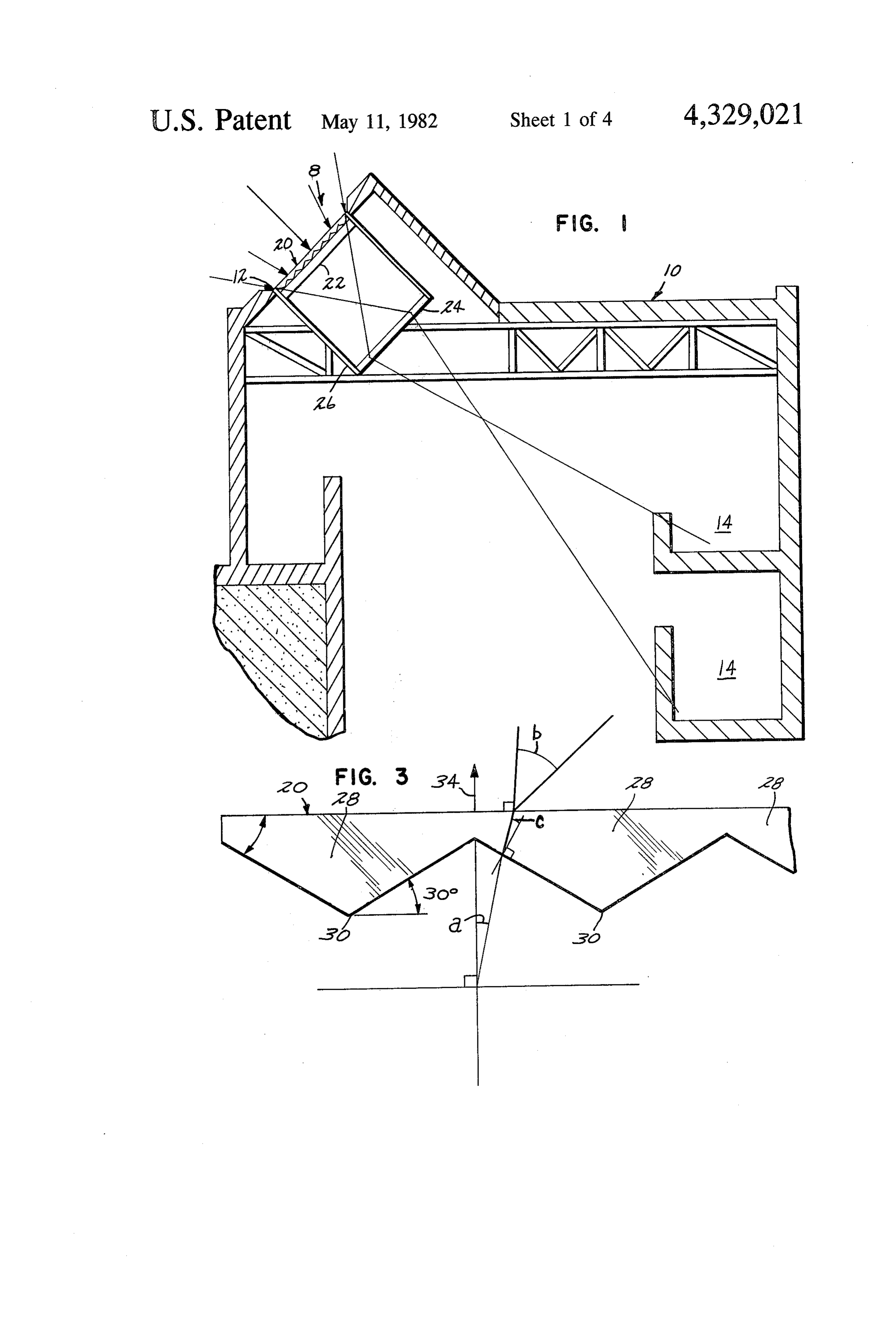
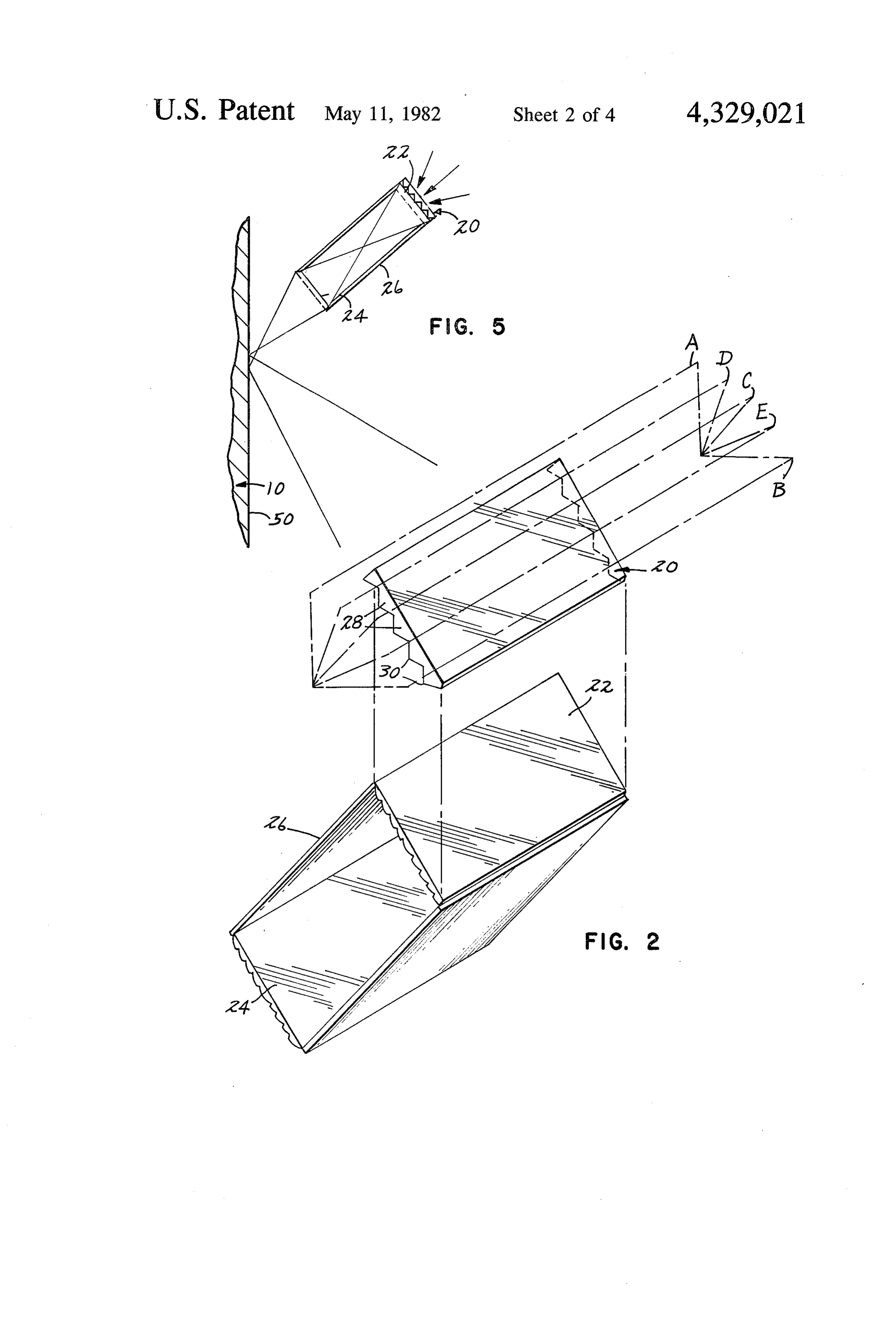
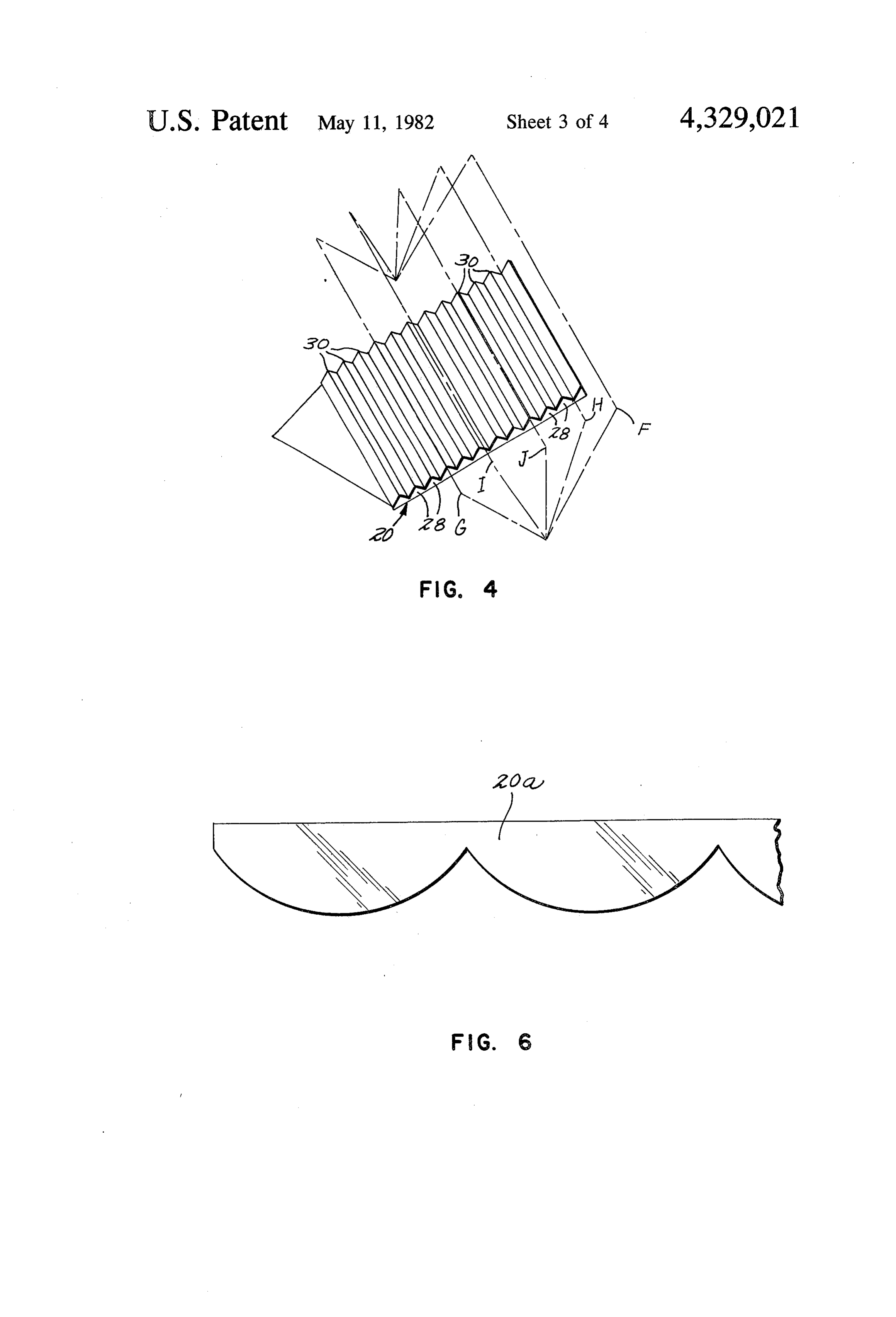
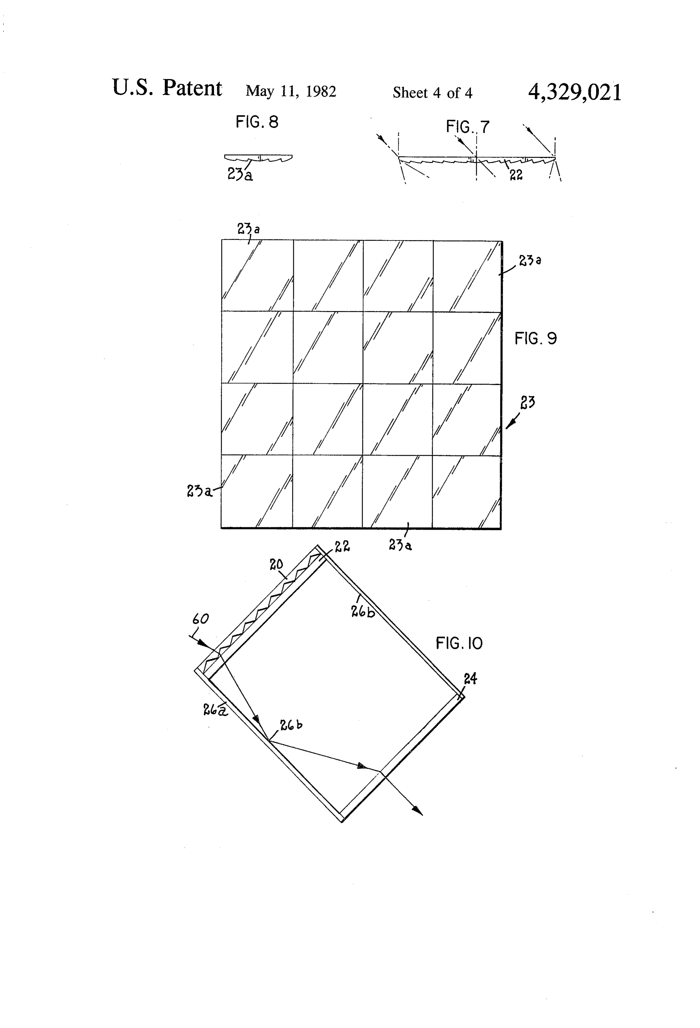
FIG. 2 is an exploded perspective view with portions methods of admitting sun into an interior space are broken away illustrating the lens portion of the present generally limited to glazing at the building envelope. invention;
FIG. 9 is a top plan view of lens 23 of an alternate
Page 2drawing sheetscan →
Page 3drawing sheetscan →
Page 4drawing sheetscan →
Page 5drawing sheetscan →
Page 6scan →
direction so as to maximize the light collected regard
PASSIVE SOLAR LIGHTING SYSTEM less of location of the sun through the various seasons. According to another aspect of this invention, the
TECHNICAL FIELD means for increasing the incident angle of light may The present invention relates to the field of interior include lighting provided by sunlight, more; particularly sys lected a longitudinal multiplier lens oriented in a north-south direction so as to maximize the light col tems which capture solar radiation passively without given day. regardless of the location of the sun throughout a requiring mechanical systems for tracking the move According to another aspect of the invention, a plu ment of the sun. 10 rality of lenses, such as Fresnel or ground lenses are BACKGROUND OF THE INVENTION located in line with the multiplier lens for adjusting the focus of the light onto a target surface to the degree of
With increasing interest in fuel conservation, the idea light of employing sunlight for interior lighting has again concentration desired.
According to a further aspect of this invention, plas become popular. While sunlight provides an inexpen 5 tic lenses could be used throughout so as to significantly sive source of interior lighting, it has been difficult to reduce the cost of this lighting system. manipulate this light so that a building interior will be According to a further aspect of the invention, lenses provided with adequate light throughout the course of of the invention are held by a frame which has mirrored the day. Because the position of the sun in the sky is surfaces to increase the amount of light reaching the constantly changing throughout the day and through 20 target surface.
the different seasons, a means must be provided for Various advantages and features of novelty which capturing these rays regardless of their orientation on characterize the invention are pointed out with particu the horizon. Numerous schemes have been developed larity in the claims annexed hereto and forming hereof. for tracking the path of the sun which required complex However, for a better understanding of the invention, electro-mechanical tracking mechanisms. One such 25 its advantages, and objects obtained by its use, reference "active' scheme is disclosed in an article by M. Duguay should be had to the drawings which form a further part and R. Edgar entitled "Lighting with sunlight using sun hereof, and to the accompanying descriptive matter, in tracking concentrators' Applied Optics, volume 16 page which there are illustrated and described preferred 1444, May 1977, which employs an active tracking embodiments of the invention.
system. The disadvantage of such systems is that they 30 DETAILED DESCRIPTION OF THE are more costly to construct thereby reducing the eco DRAWINGS nomic advantage of solar lighting and discouraging its implementation in residential construction where so Referring to the drawings wherein like numerals phisticated systems are too expensive and otherwise 35 indicate like elements:
undesirable. FIG. 1 is a view in section of the present invention Current non-moving or "passive' solar collecting installed within a building;
FIG. 2 is an exploded perspective view with portions methods of admitting sun into an interior space are broken away illustrating the lens portion of the present generally limited to glazing at the building envelope. invention;
Skylights and windows are very old techniques. The addition if frosted glass or plastic material used to scat 40 lensFIG.
3 is a fragmentary end view of the multiplier ter light has also been combined with these previous FIG. 4 is an alternate embodiment of a portion of the techniques to somewhat improve the effectiveness of present invention;
prior passive methods but does not meet the need of FIG. 5 is a schematic view of an alternative embodi providing sufficient light in the desired area throughout 45 ment of the present invention employing a mirror; the daylight hours. FIG. 6 is a view similar to FIG. 3 showing an alter The present invention has overcome the deficiencies of the prior art by providing a passive means for in nate embodiment of the multiplier lens; FIG. 7 is a side view in section of lens 22 of the pres creasing the angle at which incident light is accepted ent invention;
into a collector without physically tracking the move- so FIG. 8 is a side view in section with portions broken ment of the sun. away of lens 23a of an alternate embodiment of the SUMMARY OF THE INVENTION present invention;
FIG. 9 is a top plan view of lens 23 of an alternate
The present invention is directed to a passive solar embodiment of the present invention; and lighting system for use in lighting the interior of a build- 55 FIG. 10 is a side view in section of a portion of an ing having a light transmissive aperture therein, which alternate embodiment of the present invention. includes a means located near the aperture capable of increasing the angle of incidence which sunlight may DETALED DESCRIPTION OF THE enter aperture beyond what would enter in the absence INVENTION of this means, and a plurality of focusing lenses in line 60 Referring to the drawings in detail, there is shown in with the increasing means for focusing the light trans FIG. 1 a passive solar lighting system 8 located within mitted through the aperture to a desired surface within building 10 having a light transmissive aperture 12 the building to provide usable light for persons within therein and a target surface 14 within the building areas of the building. where interior illumination is required. Located across According to a further aspect of this invention, the 65 aperture 12 is multiplier lens 20. Directly behind multi means for increasing the incident angle of light accepted plier lens and in intimate contact therewith is lens 22. includes a longitudinal multiplier lens also known as a Alternatively, lens 22 may be spaced from lens 20 if prismatic refractor, which is oriented in a east-west desired. Located in line with lens 22 and spaced there 7 from is lens 24, Lenses 20, 22 and 24 are carried within lines F and G illustrates the increased light capture in a frame 26 which holds them in place and affixed to build given day over what would be the normal cone of ac ing 10. ceptance without multiplier lens 20, as indicated by Turning to FIGS. 2 and 3 of the drawings, lenses phantom lines H and I. Plane J is depicted normal to 20-24 can be seen in greater detail. Multiplier lens 20, lens 20. In FIG. 4, lens 20 is shown oriented so that also known as a prismatic refractor, is comprised of a longitudinal prisms 28 are facing outward toward the plurality of longitudinal prisms 28 in a side-by-side rela sun, the reverse of that shown in FIG. 2. Either orienta tionship. In actual practice, lens 20 may be stamped out tion, inward or outward, is possible for the north-south of a single sheet of plastic so that it has a plurality of and the east-west orientation of the lens 20. ridges 30 which have a prismatic or refractive effect. O The multiplier lens 20 acts as a passive solar tracking This lens may be composed of any translucent material device for the entire lens guide system which includes although plastic may be desirable to reduce the cost of lenses 22 and 24, by broadening the acceptance cone of production. Alternatively, a plurality of cylindrical the system, thus allowing it to "see" more of the sun's lenses may be formed in a single sheet in a side by side path without the need to physically re-orient the sys relationship to produce a multiplier lens 20a as shown in 15 tem. When used in combination, the multiplier lens 20 FIG. 6. Such a cylindrical lens would have essentially and guide system simulates an active solar lighting sys the same refractive effect as the prisms 28 of multiplier ten.
lens 20. Each facet of the multiplier lens refracts the sun's Multiplier lens 20 is optimally oriented so that the rays according to the angle of incidence at which the prisms 28 are longitudinally aligned in an east-west rays strike lens 20. A simple multiplier lens can be made direction. This orientation permits capture of a maximal from a plurality of linear plastic prisms of triangular amount of sunlight regardless of the season of the year cross section in side-by-side relationship manufactured without the need for mechanical tracking systems; so that there are many to a sheet. Cylindrical lenses may hence, the term "passive" or "static' system. The orien be substituted for prisms as shown in FIG. 6. Small tation of lens 20 in terms of its inclination with respect 25 pyramids can also be stamped or cast into a plastic sheet to a horizontal plane is dependent on the geographic to act as a multiplier lens.
latitude at the location of use and can be determined by Turning to FIG. 3 of the drawings, the refractive a person skilled in the art. For example, it has been effect of the multiplier lens is shown. To compare the determined for a building in Minneapolis, Minn. an increase in the cone of acceptance achieved by the inclination of 45 off the south horizon has proved satis 30 multiplier lens 20, a calculation can be made of the factory. The inclination can also be adjusted slightly at normal cone of acceptance which would be available installation to favor winter over summer or vice versa. should multiplier lens 20 be eliminated from the scheme. The physics of this orientation for use in a focusing type The normal cone of acceptance (2.a) is determined by of solar heating system is described in detail in U.S. Pat. the following formula:
No. 3,915,148 issued to Fletcher et all which is hereby 35 incorporated by reference. 2a = 2 tan (D24/2-L)
It is similarly possible to orient lens 20 so that the prisms 28 are longitudinally aligned in the north-south where orientation as shown in FIG. 4. This arrangement D24= diameter of lens 24 broadens the cone of acceptance of the multiplier lens in 40 and L = distance between lens 22 and lens 24 an east-west direction so that a maximum capture of If, for example, the diameter of lens 24 was two units light occurs for the longest number of hours in a day. A (D24=2) and the distance between the lens 22 and the trade-off between these two orientations result in that lens 24 was three units (L=3), then by making the ap one orientation (east-west) improves seasonal light cap propriate calculation, the cone of acceptance of such a ture at the cost of reducing the length of hours in a day 45 system would be approximately 37' or 18.5 to the left which light will be captured while the other orientation or right of the normal axis 34 as shown in FIG. 3. (north-south) favors optimumization of the number of Since multiplier lens 20 obeys the physical laws appli hours of daylight captured at the expense of capture cable to any other refracting lens, the light bending during certain seasons. effect of this lens can be calculated in order to design a At a latitude of 45° north the winter solstice occurs at 50 multiplier lens capable of producing the desired cone of about 22 off the horizon and the summer solstice oc acceptance. By altering the "steepness' of pitch of the curs at about 67. As shown in FIG. 2, phantom lines A facets of the individual prisms in multiplier lens 20, the and B define planes which indicate breadth of a typical refractive effect is similarly altered. The pitch in the cone of acceptance for a multiplier lens. Phantom line C lens shown in FIG. 3 is designated as 30'. With this depicts a plane located normal to the face of multiplier 55 angle known and the index of refraction for the material lens 20. Phantom lines D and E indicate planes which of which the multiplier lens is made, it is possible to illustrate what a normal cone of acceptance might be calculate the maximum angle which light can be re for an aperture without multiplier lens 20. It can be fracted by lens 20 and still be transmitted through the appreciated that the present invention, as oriented in multiplier lens to lens 24. This maximum angle of inci FIG. 2, provides substantially more light capture 60 dence is noted as angle b in FIG. 3 and represents half through the various seasons than would be possible of the cone of acceptance since the cone includes the without this device. During a given day in a season light received from both left and right sides of an axis when the sun travels essentially through a plane below normal to the surface of lens 20. By using the formula plane E, sunlight would not be gathered by the system hereinafter described, angles "c' and "a" may be calcu 8 without the use of multiplier lens 20. 65 lated as shown in FIG. 3.
By orienting multiplier lens 20 as shown in FIG. 4 so It is also possible to work in the other direction, i.e., that the individual prisms are aligned in a north-south start with an angle 'a' (the maximum angle of incidence direction, a cone of acceptance delineated by phantom which could be captured by a system without lens 20, as 8 computed by the formula above). A third alternative is with: specifications included from the vendor of such to determine angle "a' by the geometry of system ac lenses. It is desirable to locate lens 24 such that all of the cording to the factors in the above formula, choose the light passing through lens. 22, falls within the cone of desired cone of acceptance, and calculate the prism acceptance of lenses 22 and 24. It is possible to focus the
The following formula and calculations were based islight rays from lens 22 directly on lens 24; however, this on a multiplier lens with 30 prisms having an index of age to lens.24since inadvisable the heat generated may cause dam refraction of 1.49 and an angle "a' determined to be be located so that lens2422is focuses if lens made of plastic. Lens 24 can either beyond or be fore lens 24 since the desire of this system is to deliver 10 light and not an image of great clarity. By adjusting the
N sin I=N2 sin I2, position of either lens 22, lens 24 or both, it is possible to the general formula, or as derived using the 30' prisms obtain the degree of light intensity and amount of light of lens 20: spread which is desired for target 14. Obviously, when the area which must be illuminated is increased, the 15 intensity is similarly decreased.
arc sin sin (30'-a)/N}=c and
An alternative embodiment of this invention is shown arcsin sin (30-c). N2=b in FIG. 5. This embodiment includes all of the elements where of previous embodiments but in addition employs a a=as calculated in previous formula mirror 50 which is mounted on a wall of building 10. N2=Index of refraction = 1.49 for glass angles a, b, The placement of this mirror acts as an additional light and c are shown in FIG. 3 guide and permits the light rays to be directed to a 2b=cone of acceptance with multiplier target elsewhere within the building. It is within the In this case: scope of this invention that additional mirrors and/or 25 lenses could be located to further direct the light rays.
arcsin sin (30-18.5')/1.49)=7.7 =c Lenses 22 and 24 are held within a frame 26 which can be a simple bracket means to hold the lenses in and substituting where: place. It is also possible to use technology known in optical telescopes for holding focusing lenses which are arcsin sin (30-7.7")-1.49)=34 =b 30 movable relative to one another to change the area upon which the light through the system is focused.
angle a=as defined above Once the location of lens 22 and 24 are determined for angle b=maximum angle of incidence off the normal a particular area to be illuminated, there is no need to axis for a particular multiplier lens as calculated readjust their relative position and therefore the frame above and lenses can be fixed.
angle c-angle at which light entering prism at angle 35 Where space limitations are a problem, it may be b will appear off an axis normal to an inclined face important to reduce the focal length of lenses 20 and 24 of the prism as discussed above so as to reduce the overall size of the system. This may From the above calculations, it can be seen that multi be particularly important with buildings having lower plier lens 20 having 30 prisms increases the angle of acceptance from 18.5" to 34, thereby permitting the 40 ceilings.
lenses
This can be accomplished by simply choosing of shorter focal length; however, since focal capture of sunlight over a greater portion of the horizon length is related to the diameter of the lens, lenses used without physically tracking the movement of the sun. in this system, which may be two feet square, inherently Therefore, 2b=68' or an increase of 31 in the cone have long focal lengths. To overcome this problem, lens of acceptance without the need to physically re-orient 45 23 may be substituted in place of lens 22, lens 24 or both. any element of the system. Lens 23 shown in FIG. 9 comprises a plurality of Lenses 22 and 24 serve to guide light transmitted smaller through multiplier lens 20 to a target surface 14 at any togetherlenses 23a shown in FIG. 8, which are joined degree of focus desired. Lenses 22 and 24 may be made 23a are preferablyaplastic to form single sheet lens. Individual lenses of any material which is light transmissive. In the pre 50 turally the same as lenses 22Fresnel and lenses and are struc 24. FIG. 7 illustrates a ferred embodiment, plastic Fresnel lenses are chosen since they are easily made by a stamping process from side view of lens 22 and it can be seen that each lens 23a is merely a reduced version thereof. Lens 23 can be plastic sheets. In a preferred embodiment, linear eche produced on a single sheet in a stamping operation lon Fresnel refractors are employed. Lens 22 is located whereby all lenses 23a are formed simultaneously on the in intimate contact with lens 20. Light passing through 55 lens 22 will converge at its focal length. The distance same sheet of plastic. Because each lens 23a has a sub relationship between the target 14 and lenses 22 and 24 stantially smaller diameter than lenses 22 or 24, lens 23a necessarily has a much shorter focal length. Even are governed by the following equation:
though lens 23 overall has the same surface area as lens 22 or 24, the focal length is actually determined by the individual lenses. It is therefore possible to space lenses where 22 and 24 much closer to each other. S= Distance from lens 22 to lens 24 It is also possible to make certain modifications to S2= Distance from lens 24 to target 14 frame 26 to increase the amount of light directed to 1/f=focal distance of lens 24. target 14. As shown in FIG. 10, frame 26 has been re By locating lens 22 directly adjacent lens 20, it is possi 65 placed by frame 26a wherein all four walls of said frame ble to capture nearly all of the light rays passing are coated with a metallic or reflective material such through lens 20 for further refraction and guidance by that they are mirrored. This will result in increased light lens 22. The focal length of lens 22 is usually available transmission to target 14 for the following reason. Some 9 of the light passing through lenses 20 and 22 will strike 2. A system according to claim 1 wherein at least one the lens holding frame 26. If the frame has mirrored of said focusing lenses comprises a plurality of coplanar surfaces 26b as does frame 26a, light rays such as ray 60 lenses.
will be reflected off surfaces 26b and be directed 3. A system according to claim 2 wherein said copla through lens 24, ultimately striking target 14. Frame 26, nar lenses are Fresnel lenses produced on a single sheet lacking this reflective ability, would simply absorb ray of material.
60 and therefore the light transmitted to target 14 would 4. A system according to claim 1 wherein said focus be somewhat diminished. The walls of the frame 26 may ing means includes a plurality of lenses. be either linear or in the form of a single curvilinear 10 said5. passive
A system according to claim 1, 2, 3, or 4 wherein means includes a multiplier lens.
wall.
Numerous characteristics and advantages of the in the6.interior A passive solar lighting system for use in lighting of a building having a light aperture com vention have been set forth in the foregoing description, prising in combination:
together with the details of structure and function of the (a) a multiplier lens having a plurality of longitudinal invention, and the novel features thereofare pointed out 15 prisms arranged in a side-by-side relationship in the appended claims. The disclosure, however, is fixedly located in line with the aperture for increas illustrative only, and changes may be made in detail, ing the cone of acceptance for light entering the especially in matters of shape, size, and arrangement of building through the aperture; parts, within the principles of the invention, to the full (b) a first refracting lens located in line with said extent intended by the broad general meaning of the 20 prisms for receiving light transmitted through said terms in which the appended claims are expressed. prisms and focusing said light; What is claimed is: (c) a second refracting lens located to receive light 1. A passive solar lighting system for use in lighting passing through said first lens and direct said light the interior of a building having a light aperture com to a target area within the building; and prising in combination: 25 (d) at least one frame for fixedly securing said multi (a) passive means adapted to be located at a fixed plier, first and second lenses to the building, said location adjacent an aperture through a building frame having mirrored sidewalls positioned sub for increasing the angle of light acceptance stantially orthogonally to said lenses. through which sunlight may enter the aperture; 7. A system according to claim 6 wherein a mirror is (b) focusing means located in line with said passive 30 employed to direct light passing through said second increasing means for receiving light transmitted by lens to a target surface.
said passive increasing means and further transmit 8. A system according to claim 6 wherein said multi ting and directing said light to a desired target area plier lens is comprised of a plastic sheet wherein said within the building; and prisms are formed in one surface thereof and said first (c) means for holding said focusing means optically in 35 and second refracting lenses are each formed of a plastic line with said passive increasing means to receive sheet Fresnel lens.
light therefrom, said holding means including a 9. A system according to claim 6 wherein at least one frame having sidewalls substantially orthoginal to of said first and second refracting lenses is comprised of said focusing and passive means, said sidewalls a plurality of coplanar Fresnel lenses produced on a being reflective so that an increased amount of 40 single sheet of material. sk xt light will pass through said focusing means.
Provenance
- Collection
- Patents citing this work
- Pages
- 9
- Method
- pdftotext (the PDF's own text layer) + pdftoppm 300dpi page scans
- Patent office record
- patents.google.com →
- Source
- Google Patents citing-documents table
- Assignee
- Bather, Ringrose, Wolsfeld, Jarvis, Gardner, Inc.
- Published
- 1982-05-11
- Transcribed from
- patentimages.storage.googleapis.com →