

patent · US4333814A
Methods and apparatus for improving an RF excited reactive gas plasma
8 June 1982
Text
Page 1scan →
United States Patent (19)
Kiyel
(54) methods and apparatus for
Improving an rf excited reactive
Gas plasma
75) Inventor: Birol Kiyel, Hopewell, N.J.
73 Assignee: Western Electric Company, Inc.,
New York, N.Y.
51) Int. C. ................................................ C23F1/02
52 U.S. Cl. .................................... 204/298; 156/345;
3,730,873 5/1973 Pompei et al. ...................... 204/298 3,767,551 10/1973 Lang, Jr. et al. ................... 204/192 3,864,239 2/1975 Fletcher et al. .................... 204/298 4,222,838 9/1980 Bhagat et al. ...... . . 204/192 E 4,233,109 11/1980 Nishizawa ........................... 156/64
Kzzzzzzzzzzzzzzzzz
Other publications
J. S. Logan, Control of RF Sputtered Properties
Through Substrate Tuning, IBM J. Res. Develop, Mar.
J. L. Vossen et al., Thin Film Processes, Academic Press,
L. I. Maissel et al., Handbook of Thin Film Technology,
Primary Examiner-Delbert E. Gantz
Assistant Examiner-William Leader
Attorney, Agent, or Firm-A. M. Tobia
The quality of a plasma etching process is improved by applying a DC potential (28") to one of the energizing electrodes (12") in the reaction chamber (11").The DC potential withdraws a small current from the plasma which causes the reaction to produce a uniform, con trollable self-bias on the workpiece placed on the oppo site (or second) electrode.
2 Claims, 7 Drawing Figures
Drawings
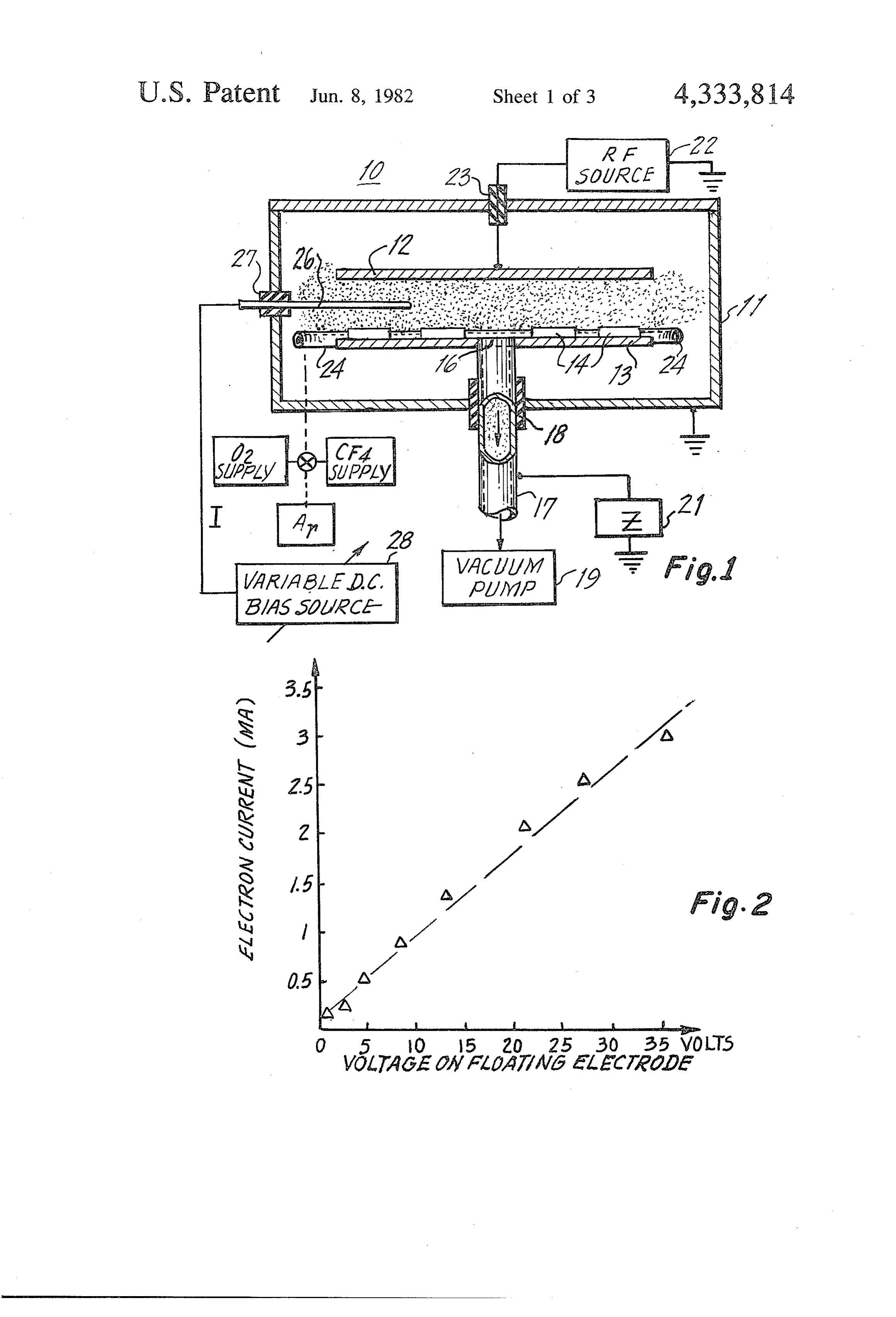
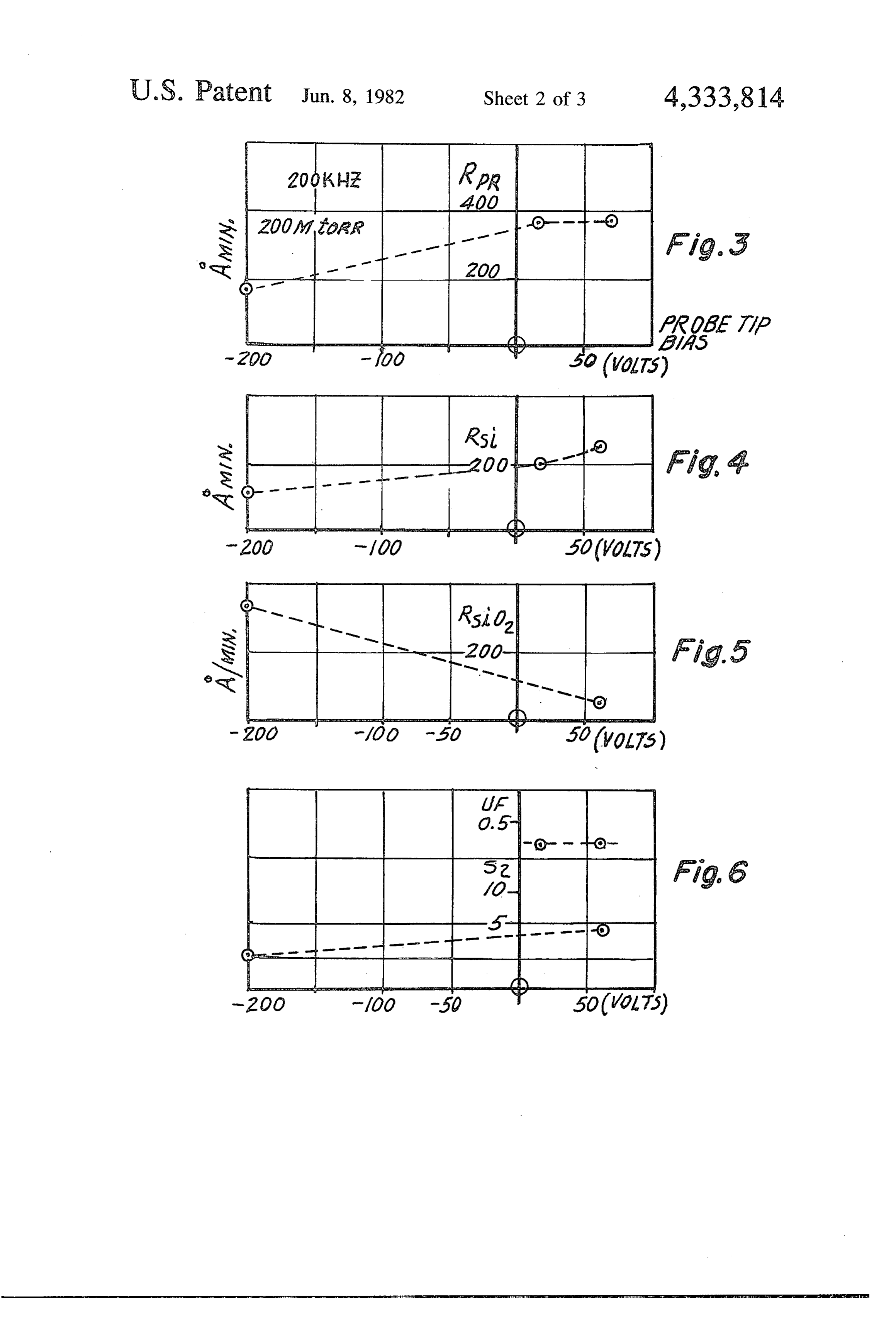
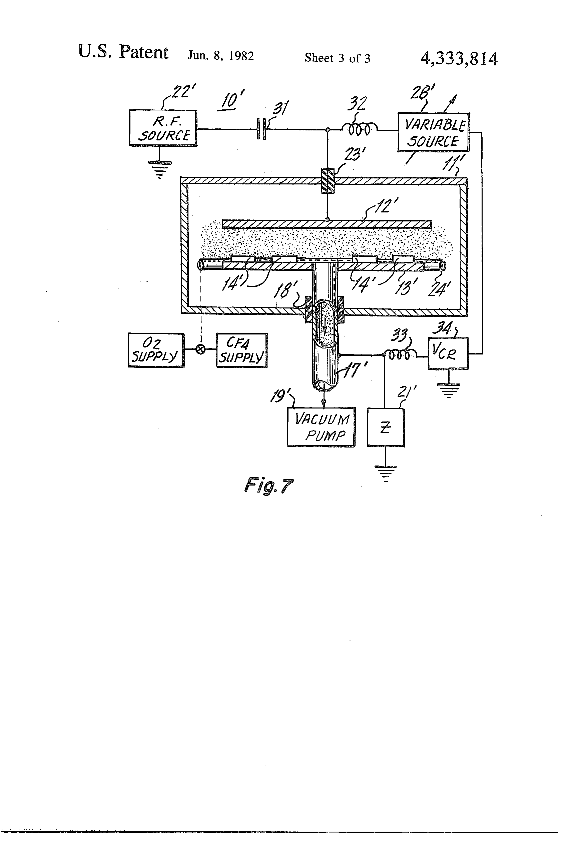
FIG. 4 is a graph showing RSi, the rate at which when an underlaying thin layer of SiO2 is reached. This polysilicon latter technique requires an etch process that will selec plied to theisprobe;
FIG. 7 depicts an alternate embodiment of the inven What is claimed is:
Page 2drawing sheetscan →
Page 3drawing sheetscan →
Page 4drawing sheetscan →
Page 5scan →
surface of the wafer, as desired. The amount of charge
METHODS AND APPARATUS FOR IMPROVING can be varied by altering the amount of current with AN RF EXCTED REACTIVE GAS PLASMA drawn from the plasma. The process according to the FIELD OF THE INVNENTION invention puts the potential where it is needed-on the surface of the wafer-rather than on the support elec
Broadly speaking, this invention relates to reactive trode.
gas plasmas. More particularly, in a preferred embodi The invention and its mode of operation will be more ment, this invention relates to methods and apparatus fully understood from the following detailed descrip for improving the physical and chemical properties of tion, when taken with the appended drawings in which: an RF-excited, reactive gas plasma process, and specifi 10 cally to methods and apparatus for improving the uni BRIEF DESCRIPTION OF THE DRAWINGS formity and repeatability of the reaction that occurs on FIG. 1 is a cross-sectional view of an illustrative at least one surface of a workpiece exposed to the RF reaction chamber including a current probe according plasma.
15 to the invention;
BACKGROUND OF THE INVENTION FIG. 2 is a graph showing the manner in which the voltage developed across a "floating' electrode in the
In the manufacture of integrated circuits, and the like, reaction chamber shown in FIG. 1 varies as a function it is often necessary to etch portions of a silicon wafer, of the current withdrawn from the plasma; for example, through the windows of an overlaying, FIG. 3 is a graph showing RPR, the rate at which a patterned mask manufactured from some suitable resist 20 photoresist is etched, as a function of the potential ap material. Alternatively, it may be necessary to etch a thick layer of polysilicon and to terminate the etch plied to the probe;
FIG. 4 is a graph showing RSi, the rate at which when an underlaying thin layer of SiO2 is reached. This polysilicon latter technique requires an etch process that will selec plied to theisprobe;
etched, as a function of the potential ap tively etch polysilicon but which is inert to SiO2. 25
In both of the above cases, it is customary to employ FIG. 5 is a graph showing RSio, the etch rate for a wet chemical etch; however, considerable interest has SiO2, as a function of the voltage applied to the probe; been expressed recently in the use of reactive gas plas FIG. 6 is a graph showing both the undercut factor mas to perform the etching. The reason for this is that UF and the selective etch rate S2 for silicon and SiO2, as reactive gas plasmas have been found to be anisotropic 30 a function of the potential applied to the probe; and under some circumstances and, in general, are cleaner, FIG. 7 is a cross-sectional view of a second illustra more efficient and far less troublesome to use than wet tive embodiment of the invention.
chemical etches.
A plasma etch is typically carried out in an evacuated DETAILED DESCRIPTION reaction chamber, for example, the reaction chamber 35 FIG. 1 depicts a first illustrative embodiment of the disclosed by Reinberg in U.S. Pat. No. 3,757,733, which invention and a typical operating environment therefor. issued Sept. 11, 1973, which patent is hereby incorpo It must be emphasized from the outset that while the rated by reference as if more fully set forth herein. preferred embodiment of the invention, to be discussed As might be expected, the potential of the wafer in detail below, pertains to plasma etching, the inven surface, with respect to the plasma, has been found to tion may also be used in plasma deposition processes, play an important role in an RF plasma etching process. with equal success. More specifically, when the inven Unfortunately, heretofore, no satisfactory way has been tion is applied to a plasma deposition process, the sur found to establish this potential independently of the face stress, the index of refraction and the porosity of other operating parameters in the reaction chamber. the deposited layer are all improved. It should also be Furthermore, the self-bias that is induced on the surface 45 emphasized that the invention is not restricted to use of the wafer by the plasma itself has been found to be with silicon workpieces; indeed, any workpiece that is very sensitive to almost all of the parameters of the affected by a reactive gas plasma is encompassed by the etching process, including the system geometry. As a claims of this invention.
result of the above, prior art plasma etching processes Turning our attention back to plasma etching, FIG. 1 have been plagued with irreproducibility and unpre 50 dictability, resulting in very low yield. Some attempts depicts a Reinberg-type reaction chamber 10 compris to correct this problem have been made, for example, ing a hollow, cylindrical member 11 constructed, for example, of aluminum, and having a pair of cylindrical, by placing a DC bias on the electrode that carries the spaced-apart, disc-shaped electrodes 12 and 13 posi wafer, or by grounding the electrode through either a resistive or a capacitive impedance. Unfortunately, such 55 tioned therein. The upper surface of lower electrode 13 attempts have not been successful for the simple reason supports a plurality of workpieces 14. Although not shown in the drawing, one skilled in the art will appre that the potential of the electrode is not necessarily the ciate same as the potential of the surface of a wafer supported that a corresponding plurality of workpieces could by the electrode. This is especially true if the wafer to be affixed to the lower surface of upper electrode 12 if be etched includes a dielectric, interlevel layer, for 60 it is desired to increase throughput. Electrode 13 has a example, a thin film of SiO2. central aperture 16 formed therein and is connected to a
Summary of the invention
hollow, metal pipe 17 which is insulated from member 11 by means of an insulated, hermetic bushing 18. The
As a solution to these and other problems, I propose lower end of pipe 17 is connected to a vacuum pump 19 an RF plasma etching process wherein a small current is 65 which serves to maintain the vacuum within the reac withdrawn from the plasma during the etching process. tion chamber and also to remove spent gases from the This current withdrawal scatters oppositely charged chamber, Pipe 17 is connected to ground via a resistive particles onto the surface of the wafer, charging the or capacitive impedance 21.
Page 6scan →
To test the hias produced on a floating electrode by tively thick layer of polysilicon and an overlaying layer drawing current from the probe, the output of a radio of photoresist.
frequency source 22, illustratively operating at 13.5 FIG. 3 is a graph which depicts iPR, the etch rate in MHz, is connected to upper electrode 2 through the angstroms per minute of a typical photo resist in a walls of meinber 1 by means of an insulated, hermetic 5 plasma which was excited at a frequency of 200 KHz. bushing 23. The gas which is to form the plasma, e.g., and at a pressure of 200 millitorr, as a function of the the inert gas Air, is connected to a foraminous, toroidal potential on the probe using a CF4 and O2 gas plasma. pipe 24, which is positioned within member 12, coaxial FIG. 4 similarly shows Risi, the etch rate for polysilicon with electrode 13 and proximate the edges thereof. A under similar conditions, while FIG. 5 shows rSiO2, the probe 26 passes through the wall of member 1 by O etch rate for SiO2, FIG. 6, on the other hand, is a graph means of ail insulating bushing 27 and extends into the showing the selectivity of the process, that is, the ratio region of space where the plasma will exist when the of the etch rate of silicon to the etch rate of Si32, as a gas supply is turned on and Rif-source 22 activated. The function of the potential applied to the probe. The same other end of probe 25 connects to a variable DC bias graph also shows the undercutting factor JF. source 28. in operation, and when the plasma is acti 15 For practical considerations, in the experiments to be vated, this permits the operator to alter the amount of described it was the probe voltage, rather than the volt current tihat is withdrawn from the plasma by means of age on the wafer surface, that was actually monitored. probe 23. However, since the current withdrawn by the probe is FIG. 2 is a graph which illustrates the results of an a unique function of the probe voltage and, as shown in experiment whicil ', as performed using the apparatus 20 FIG. 2, since the potential on a 'floating surface in shown in FiG. A. the i plasina employed for this experi contact with the plasma is a linear function of the probe ment was an Air plasia and lower electrode 3 was current, the DC voltage on the wafer can be assumed to connected to ground via a high impedance so that, in be a function of the probe voltage.
(effect, the electrode 33 was floating. As may be seen Thus, FIGS. 3 through 6 clearly demonstrate that not from the graph, there is a nost a linear relationship 25 only do the various etch rates change with the voltage betwecn the current withdrawn from the plasma by the established on the surface of the wafer but also the probe and the potential that is established on the elec relative etch rate, implying the existance of two chemi trode 13. Since the plasia potential was constant dur cal processes, one driven by neutral species and he ing the 2xperiment, the potential between the electrode other driven by charged species.
3 and the plasiina varied in a similar linear fashion. 30 Now, in a successful plasma etch process, we want There does not yet exist a rigorous physical explanation the etch rate of the photoresist to be low, the etch rate for the observed phenomena; however, it is known that of the polysilicon to be relatively high and the etch rate the electrical conditions in the vicinity of the probe of the dielectric SiO2 to be relatively low. FIG. 3 shows must satisfy Sirchoff's law. Thus, the electron current that as the potential on the probe is increased, the etch withdra', in from the probe must be exactly matched by 35 rate of the photoresist increases. Of course, it would be ail ion cit 1'rent which is injected into the plasma. better if the etch rate of the photoresist were to decrease flow, from a 3C standpoint, the upper electrode is however, even at a probe potential of -- 60 volts it will grollided. Therefore, if we '','ere dealing with a simple be seen that the etch rate of the photo resist is no higher circuit, current would low from the zero impedance than it would be at -|-5 volts, say. This, the instalt path and we world be unable to establish a 3D C potential 40 invention leaves the etch rate of the photoiesist essen on the floating electrode. But, as shown in Fig. 2, we tially where it is with prior art plasma eiching processes do establish a DC potentiai on the floating electrode. and we have neither lost nor gained ground with re The isost likely explanation for this totally unexpected spect to the etching of the photoresist. ii owever, FIG. result is that the trajectory of the ions leaving the probe 4. deinonstrates that the etch rate of the polysilico depends on the boundary conditions of the probe itself 45 increases slightly with increasing probe bias, which is and not on the boundary conditions established by the desirable. FIG. 5 however, is the most dramatic graph electrodes. Thus, by an appropriate choice of probe and clearly shows a significant decline in the etch rate location, the ions injected by the probe will almost all of the dielectric SiO2 with increasing probe bias, which end up on the electrodes (or on the workpieces Sup is of great commercial significance. As show, in in G. 3, ported by the eiectrodes) and not lost in the plasma, the selectivity of the process S2, defined as the ratio o resulting in a controllable, self-bias on the electrodes. RSi/RSiO2, increases with increasing probe bias; this is Cine should not be iead in to a false comparison be the instant invention dramatically in proves over ti g tviyeen the instant invention and other known devices, prior art. FiG. 6 also shows that the undercut factor is for example, the vacuum triode. Probe 26 is not a con neither increased or decreased by the insiant invention, trol grid. Further, as is well known triodes work by 55 which is also of commercial significance. retai"cling elections--a potential effect-but no such These graphs shown in FGS. 3-3 clearly demon mechanisin is present in the instant invention. The ex strate the role of the energy of the charged species in periinefits that were conducted, and the graph sihown in plasma etching. Furthermore, the noted pai'abolic varia FiG. 2, clearly establish that the effect which is ob tion of the etch rates over the surface of ille wor:fiece served in the instant invention is a current effect. As 60 directly demonstrates the importance of the ion trajec proof of this, it was observed that by use of two differ tories and the flux. This variation further confirgins our ent probes, with differing potentials but the same probe understanding of the role of the probe as a charge scat current, the Sarine Seif-bias is achieved, which would not ee.
be tile case with a triode device. The arrangement shown in FiG. S is not the optimum illet is lov, consider tile workpieces themselves and, 65 arrangement for actual industrial application becai Se , a series of experiments that was conducted the probe tends to disturb the spatial unifornity within piece coin prising a silicon wafei having, in the reaction chamber and the ion trajectories are fine: O'Cai, a C not uniform over the wafers.
Page 7scan →
FIG. 7 depicts an alternate embodiment of the inven What is claimed is:
tion which achieves the same results without the use of 1. Apparatus for controlling the plasma etching of at a probe. As shown, reaction chamber 10' is essentially least one surface of a workpiece which comprises: identical to reaction chamber 10 shown in FIG. 1 ex a hermetically-sealed reaction chamber; cept that in FIG. 7 the energy from RF-source 22' is 5 first and second, spaced-apart, electrodes positioned applied to electrode 12' through a coupling capacitor within said chamber, said workpiece being sup 31, rather than directly. In this embodiment, variable ported by at least said second electrode for expo DC voltage source 28' is not, however, connected to a sure to the plasma;
probe but, rather, to the upper electrode 12", via an means for supplying at least one gas species to said RF-choke 32. A feedback circuit is also incorporated to 10 reaction chamber;
maintain the DC current withdrawn from the plasma by means for maintaining a predetermined level of vac source 28' at a substantially constant level. This feed uum within said chamber, said means also serving back circuit comprises a voltage-controlled-resistor 34 to exhaust spend gases and reaction by-products which is coupled to the lower electrode 13", via a sec from the chamber;
ond RF-choke 33. 15 a source of RF energy for establishing an alternating In operation, O2 and CF4 gases are supplied to the field between said first and second electrodes chamber, via foraminous, toroidal pipe 24' and RF thereby to excite said gas species to form an RF source 22' energized to create a reactive plasma within reactive gas plasma;
the chamber. At the same time, variable DC source 28 a DC blocking capacitor intermediate the output of withdraws a fixed DC current from the plasma, via 20 said source of RF energy and said first electrode; upper electrode 12'. RF-choke 32 ensures that no RF a variable source of DC potential; current can enter DC source 28' or the feedback circuit an RF-choke interconnecting a first output terminal while, at the same time, coupling capacitor 31 ensures of said variable source of DC potential and said that no DC signal is fed back into RF-source 22". first electrode;
The DC potential which is developed on electrode 25 a voltage-controlled-resistor having a control elec 13' (which is not necessarily the same as that which is trode connected intermediate a second output ter developed on the surface of the workpieces) is fed, via minal of said variable DC source and ground; and RF-choke 33, to the voltage-controlled-resistor 34 and, an RF-choke interconnecting the control electrode of if for any reason there should be a tendency for the said voltage-controlled-resistor and said second current withdrawn from the plasma to increase or de 30 electrode.
crease, the VCR adjusts itself, in an offsetting manner, 2. The apparatus according to claim 1 wherein said to maintain the current withdrawn from electrode 12" at second electrode is connected to ground through an a constant level. impedance which is substantially greater than the impe One skilled in the art may make various changes and dance of either said alternating field establishing means substitutions to the layout of part shown, without de 35 or said variable DC source.
parting from the spirit and scope of the invention. k sk x sk sk
Page 8scan →
UNITED STATES PATENT AND TRADEMARK of FICE
CERTIFICATE OF CORRECTION Page 1 of 2
:NVENTOR(S) . B. Kuyel it is certified that error appears in the above-identified patent and that said Letters Patent is hereby corrected as shown below:
On the title page, under the section entitled "References
Cited" the following references should be listed:
3528,387 9/1970 Hamilton ll8/49. l. 3, 664, 942 5/1972 Havas et al. 204/l92 4,085 022 4/l978 Wechsung et al. 204/92-E "Providing individual Etchstops for Wafers in
Reactive Ion Etching" by L. M. Ephrath, IBM
Technical Disclosure Bulletin Vol. 20 No llA,
"Ion Etch Technique for Fabrication of Ultrathin
Films" by R. B. Laibowitz and R. T. C. Tsui, IBM
Technical Disclosure Bulletin Vol. lo, No. 10,
The reference which reads "J. S. Logan, Control of RF Sputtered Properties" should read --J. S. Logan, Control of RF Sputtered Film
Column 2, line 26, "RSiO"
Should read --RsiO2- - -
CC lumn 3, line 42, "do" should read --do -- ; line 46, "not" should read --not-- ; line 5 4 "not" should read
Page 9scan →
United states patent and trademark office
CERTIFICATE OF CORRECTION Page 2 of 2 it is certified that error appears in the above-identified patent and that said LetterS Patent are hereby Corrected as shown below:
Column 6, claim l, line l3, "spend" should read -- spent--.
signed and Scaled this
Twenty-fourth D 2 y O) f January 1984
Seal
Attest:
Gerald rossing off
Attesting Officer Commissioner of Patents and Trademarks
Provenance
- Collection
- Patents citing this work
- Pages
- 9
- Method
- pdftotext (the PDF's own text layer) + pdftoppm 300dpi page scans
- Patent office record
- patents.google.com →
- Source
- Google Patents citing-documents table
- Assignee
- Western Electric Company, Inc.
- Published
- 1982-06-08
- Transcribed from
- patentimages.storage.googleapis.com →