

patent · US4335707A
Solar energy collector and energy storage cell
22 June 1982
Text
Page 1bibliographic recordscan →
United States Patent (19) 4,335,707 Lindenbauer N Jun. 22, 1982
54 SOLAR ENERGY COLLECTOR AND 3,822,692 7/1974 Demarest ............................ 126/271 ENERGY STORAGE CELL 4,000,734 1/1977 Matlock et al. 126/27 4,066,062 1/1978 Houston .............................. 126/424 76 Inventor: Leo K. Lindenbauer, Box 1372, 4,203,426 5/1980 Matlock et al. ..................... 126/425 Wickenburg, Ariz. 85358 4,258,698 3/1981 Sales .................................... 26/440 21 Appl. No.: 202,595 Primary Examiner-James C. Yeung 22 Filed: Oct. 31, 1980 Attorney, Agent, or Firm-Warren F. B. Lindsley Int. Cl. ................................................. F24J 3/02 ABSTRACT 52 U.S. Cl. ..................................... 126/440; 126/424 An improved sun-tracking solar energy collector in Field of Search ............... 126/438, 439, 424, 440, constant focal communication with the rays of the sun 126/451, 436, 442 during daylight hours and in which the moving element e is made compact and inexpensive by incorporating References Cited therein only the function of receiving and redirecting
1,220,091 3/1917 Goff .................................... 26/424 3,155,849 11/1964 Haring et al. ....................... 126/451 10 Claims, 6 Drawing Figures
t S. 7 & Ž es z/A 7 N Ny N7 N/
NW2 /2 /2
Drawings
Page 2drawing sheetscan →
Page 3scan →
that its relative position to the source of heat will re
SOLAR ENERGY COLLECTOR AND ENERGY main constant.
STORAGE CELL In the typical sun-tracking solar collector, the mov ing collector has incorporated therein the energy stor
BACKGROUND OF THE INVENTION 5 age elements, such as water pipes. A flexible or a rotat The rapid expansion of the world's population cou ing coupling is therefore required to carry the water or pled with the accelerated technological development of other energy storage medium from the moving collec large sectors of the world has produced a dramatic tor assembly to a stationary energy conversion or utili zation system. Such flexible or rotating couplings add increase in the demand for energy in all forms including O cost and complexity to the system and introduce a po fuels and electricity for heating, lighting, transportation and manufacturing processes. The construction of hy tential ures.
for operating malfunctions and equipment fail
The incorporation of the storage elements in the droelectric facilities and the development of fossil fuel tracking assembly also adds weight and bulk to the resources has continued at a rapid rate, but it becomes assembly. These factors adversely affect equipment cost increasingly evident for a number of reasons that these 15 to an even greater degree.
efforts are inadequate to keep pace with the demands of U.S. Pat. No. 3,822,692 also discloses the use of lens the growing population.
In the face of these growing demands and limited for directing the solar energy to tubes involved in a resources, there is one source of energy which is readily closed fluid flow circuit with a pressure sensing unit available to every country in the world in virtually 20 provided for operating a shade to cover the lens under unlimited quantities. This virtually untapped source is predetermined conditions.
solar energy. Further improvements in solar collectors, however, The interest in this almost boundless resource and in are needed. There is, in particular, an urgent need for a its development and harnessing for use in homes and suntracking collector that during daylight hours is in factories is rising as other resources dwindle. Its desir 25 constant focal communication with the sun and is ability is further enhanced by the fact that solar energy formed from a basic building unit which may be multi may be converted to practical use without the hazard of plied in number and assembled into an array to meet the environmental contamination. energy needs of a particular job to which it is applied. DESCRIPTION OF THE PRIOR ART SUMMARY OF THE INVENTION
Until recently, the development of solar energy col In accordance with the invention claimed, an im lectors has been associated for the most part with pro proved sun tracking solar energy collector is provided grams involving military and space applications while which is in constant focal communication with the sun only limited attention has been given to broad consumer during daylight hours when the sun is shining and is use. As a result, there is a great potential for improve 35 compact and inexpensive by virtue of the elimination of ments in existing collection devices that will result in all energy storage elements from the moving mecha nism.
reduced manufacturing costs and improved thermal efficiencies. It is, therefore, one object of the present invention to Once such device known as a flat plate collector is provide an improved sun-tracking solar energy collec made of metal and glass with one or more layers of glass 40 tor.
laid over a blackened metal plate. Air spaces are pro Another object of this invention is to provide a sun vided between the layers of glass and air or water passes tracking solar collector in which the bulk and weight of through tubes under the metal plate to remove the col the moving element are reduced to a minimum. lected thermal energy. The layers of glass in coopera A further object of this invention is to provide a tion with the blackened metal plate act as a heat trap, 45 sun-tracking solar collector in which the moving ele letting in the sun's rays but keeping most of the heat ment has the sole function of capturing and redirecting from escaping again. . . . .. . the rays of the sun, all other functions being served by A major disadvantage of the flat plate collector is that equipment mounted on a stationary platform. it must be very large in order to collect sufficient en A still further object of this invention is to provide a ergy, the large size resulting in part from the fact that 50 sun-tracking solar collector in a form requiring no flexi except for brief periods during the day, its surface is not ble or rotating couplings for the transfer of a storage perpendicular to the rays of the sun. medium between the moving platform and associated A second disadvantage is that the flat plate collector stationary equipment.
does not permit the concentration of solar energy at a A still further object of this invention is to provide a localized point as needed for the most effective heating 55 sun-tracking solar collector which is in constant com of the water and the conversion of water to steam such munication with the sun's rays and by virtue of its basic as required in certain solar-to-electrical conversion pro cell configuration can be built up in any size array to fit CeSSS. the energy needs of the job to which it is to be applied. Parabolic reflectors have been utilized in the past Further objects and advantages of the invention will along with sun tracking mechanisms in connection with 60 become apparent as the following description proceeds various schemes for the collection, conversion and utili and the features of novelty which characterize this zation of solar energy. Such equipment is described in invention will be pointed out with particularity in the U.S. Pat. Nos. 4,000,734 and 4,203,426. claims annexed to and forming a part of this specifica At best, the prior art heat exchangers have been ex tion.
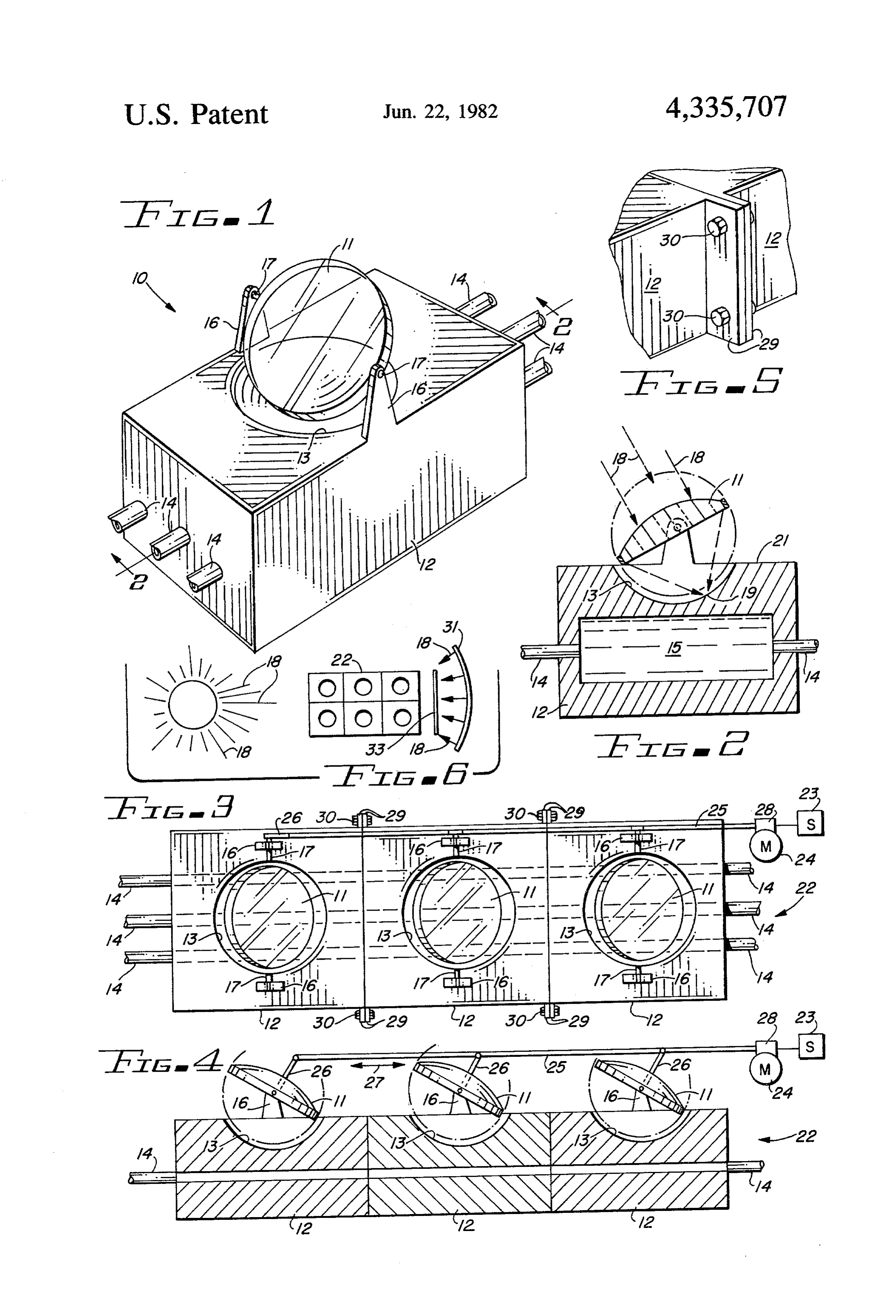
tremely inefficient even to the point where it is neces 65 BRIEF DESCRIPTION OF THE DRAWING sary to incorporate thereinto an elaborate system of gears and racks or other means to shift or otherwise The present invention may be more readily described change the positions of the exchange or collector unit so by reference to the accompanying drawing in which:
Page 4scan →
FIG. 1 is a perspective view of an improved sun that pass through lens 11. When the position of the sun tracking solar collector cell embodying the invention; is directly above cell 12, a maximum amount of energy FIG. 2 is a cross-sectional view of the collector cell is collected at surface 21; at other times as in the early of FIG. 1 as seen along line 2-2 thereof; morning or later afternoon, the collected energy is lim FIG. 3 is a top view of a collector array comprising ited for the most part to that collected by lens 11 which a number of cells of the type shown in FIGS. 1 and 2 is instrumental in directing rays 18 of the sun to the connected together to utilize a common tracking mech surface of the depression 13.
anism and a common water circulation system; The collected solar energy received by the surfaces FIG. 4 is a side view of the collector array of FIG. 3; 13 and 21 is carried by the thermally conductive metal FIG. 5 illustrates an optional mechanical feature that 10 of cell 12 to the water or other medium passing through may be incorporated in the cell structure to facilitate the or contained within pipes 14 and chambers 15. coupling of cells together to form an array; and As shown in FIGS. 3 and 4, the individual cells 12 FIG. 6 illustrates the optional use of a concentrating may be bolted together to form an array 22 in which the mirror and a flat plate mirror in conjunction with the pipes 14 are common to all of the cells 12 comprising collector cell or array of the invention. 15 the array 22 or the pipes of each cell may be intercon DESCRIPTION OF THE PREFERRED nected in a series arrangement by suitable pipe connec EMBODIMENT tion means well known in the art. The water or other medium thus passes serially through the connected
Referring more particularly to the drawing by char cells, collecting thermal energy from each cell. acters of reference, FIGS. 1 and 2 disclose an improved A common sun sensor 23 and drive motor 24 are sun-tracking solar collector cell 10 comprising a sun employed to actuate a rail 25 which is coupled to an tracking lens 11 pivotally supported over an energy extended pivot pin 17 of each of the several lenses 11. storage cell 12. The coupling to each of the pivot pins 17 is by means of Lens 11 is preferably a double convex lens which has a control arm 26 which is rigidly secured at a right the characteristic of receiving parallel rays of light and 25 angle to the end of pivot pin 17. The outer ends of the concentrating them at its focal point but may be any individual control arms 26 are pivotally connected to other form of lens structure and still fall within the rail 25 so that as rail 25 is moved in directions 27, the scope of this invention. lenses 11 are rotated about their axes as defined by pivot The storage cell 12 has the overall form of a cube or pins 17. Thus, through the utilization of sensor 23 and a rectangular block which preferably is formed from a 30 motor 24 which is coupled to rail 25 through a gear solid block of copper, aluminum or other thermally mechanism 28, the several lenses 11 are caused to track conductive metal. Because it is desirable to mount the the course of the sun across the sky. circular lens 11 in as close proximity as possible to cell To facilitate the mechanical assembly of cells 12 in an 12, an identation or depression 13 is formed in the top array 22, perpendicularly extending flanges 29 may be surface of cell 12. This depression is preferably one 35 provided at the edges of cells 12. Bolts 30 are passed having a spherical contour that will provide clearance through aligned holes in flanges 29 to secure the indi for lens 11 as it is tilted about its mounting axis. vidual cells 12 together. Alternatively, the array 24 may Also incorporated in the cell are passageways for have several cells 12 cast and machined as a single block water or another medium for collecting heat from cell rather than individual cells connected together in the 12 and carrying the heat to an energy conversion sys manner shown.
tem or to the point of use. The passageways may com As indicated earlier, the energy collected by means of prise one or more pipes 14 that pass unidirectionally lens 11 is supplemented by energy collected directly through openings in the cell or they may comprise from the sun at surface 21. To maximize the energy cylindrical openings in the cell formed when the blocks collected at surface 21, externally mounted concentrat are cast or they may be formed by subsequent drilling or 45 ing mirrors 31 may be employed as shown in FIG. 6. In machining. Enlarged openings or chambers 15 may be such an arrangement, the rays 18 from the sun 32 are provided, if desired, in the interior of cell 12 to increase reflected by mirrors 31 to the surface 21 of the solar the capacity provided for the medium. collector cell 10. The intensity of the sun's rays at sur Lens mounting supports 16 are provided for the piv face 21 is significantly increased in this manner. otal mounting of lens 11 and are located at opposite 50 In a similar fashion, a flat mirror 33 may be employed sides of depression 13 rising vertically from the top to extend the capability of lens 11 to lower angles of the surface of cell 12. Pivot pins 17 extending outwardly sun for which the focal point of lens 11 would not other along a common diameter of lens 11 pass through hori wise strike the surface 13. A flat mirror is needed in this zontally aligned holes in supports 16. The lens may be case to maintain the parallel pattern of the sun's rays rotated about this pivotal support to be directed toward 55 directed to lens 11.
the sun and to follow the sun as it moves across the sky. It will be recognized that an improved sun-tracking As shown in FIG. 2, when lens 11 is directed toward solar collector has been provided which through its lens the sun, the sun's rays 18 are received as parallel rays system is in constant focal communication with the aligned with the optical axis of the lens. The parallel sun's rays as the sun moves across the sky during the rays pass through lens 11 and converge on the opposite 60 course of the day in accordance with the stated objects side thereof at its focal point 19 which preferably lies on of the invention. The only moving element of the col the surface of the spherical depression 13. lector is lens 11 which receives and redirects the rays of The surface of depression 13, as well as all other the sun to the storage cell 12. A highly compact and surfaces of cell 12 that are exposed to the sun, may be inexpensive tracking system is thus provided that re painted black to enhance their capability for absorbing 65 quires no flexible or rotating fluid couplings. Further, the impinging rays of the sun. Solar energy is thus col the claimed cell configuration can be built up to any size lected from the direct rays of the sun on the flat surfaces array to fit given energy requirements by a predeter 21 surrounding the depression 13 as well as from rays 18 mined combination of the cell disclosed.
Page 5scan →
Although but a single embodiment of the invention 7. The solar energy collector set forth in claim 6 in has been illustrated and described, it will be apparent to further combination with: those skilled in the art that various changes and modifi means for fastening the first and second blocks to cations may be made therein without departing from 5 gether in a unitary structure.
the spirit of the invention or from the scope of the ap further The solar energy collector set forth in claim 6 in pended claims. combination with:
What is claimed is: means for connecting both lens of the blocks to 1. A solar energy collector comprising: gether, and a block of heat absorbing material, a sun tracking means connected to said means for a lens pivotally mounted on a surface of said block for 10 causing the lens of both blocks to follow in unison the movement of the sun.
receiving the rays of the sun, 9. The solar energy collector set forth in claim 1 in an indentation comprising a spherical configuration further combination with:
formed in said surface of said block juxtapositioned a further plurality of blocks of heat absorbing mate to said lens, 15 rial, said indentation providing clearance for the lens as it a plurality of lenses one for each of said plurality of is pivoted about its mounting axis, and blocks, at least one fluid conducting passageway traversing each of said plurality of lenses being pivotally said block for causing the fluid passing there mounted on a surface of the associated block for through to absorb the heat of said block. 20 receiving the rays of the sun, 2. The solar energy collector set forth in claim 1 a plurality of indentations one formed in the surface wherein: of each of said blocks juxtapositioned to the associ said passageway interiorally of said block is enlarged. ated lens, 3. The solar energy collector set forth in claim 1 said indentations provide clearances for said plurality wherein: 25 of lenses as they pivot about their mounting axes, said passageway comprises a plurality of pipes ex a plurality of additional passageways traversing each tending unidirectionally through said block. of said blocks, 4. The solar energy collector set forth in claim 1 in means for connecting said passageway of said first further combination with: block and said passageways of said plurality of means for pivotally rotating said lens to follow the 30 blocks in series,
S. means for fastening said block and blocks together in 5. The solar energy collector set forth in claim 3 a unitary structure, and wherein: means for connecting said lens and lenses together, said means comprises a sun tracking mechanism. and 6. The solar energy collector set forth in claim 1 in 35 a sun tracking means connected to said means for further combination with: causing the lens of both blocks to follow in unison a second block of heat absorbing material, the movement of the sun. a second lens pivotally mounted on a surface of said 10. The solar energy collector set forth in claim 1 second block for receiving the rays of the sun, wherein:
a second indentation in the surface of said second 40 said block is provided with a plurality of additional block juxtapositioned to said second lens, lenses, said second indentation providing clearance for said further additional indentations one formed in said second lens as it is pivoted about its mounting axis, block juxtapositioned to each of said plurality of a second fluid conducting passageway traversing said lenses, and second block, and 45 means for pivotally rotating in unison all of the lenses means for connecting in series the passageways of the for tracking thesksun.a k is st first and second blocks to form an array.
Provenance
- Collection
- Patents citing this work
- Pages
- 5
- Method
- pdftotext (the PDF's own text layer) + pdftoppm 300dpi page scans
- Patent office record
- patents.google.com →
- Source
- Google Patents citing-documents table
- Assignee
- Lindenbauer Leo K
- Published
- 1982-06-22
- Transcribed from
- patentimages.storage.googleapis.com →