

patent · US4338918A
Unitary structure and method for utilizing solar energy
13 July 1982
Text
Page 1scan →
Milburn, Jr.
54 unitary structure and method for
Utilizing solar energy
75 Inventor: William W. Milburn, Jr., Boulder,
Colo.
73) Assignee: Thomas W. O'Rourke, Boulder,
Colo.
Related U.S. Application Data
; A 8 - d - a - - - - - - - - - - - - - - - - - - - - - - - - - - - -i2673.
58) FieldE.A.R.E.E.E.E. a WV 541 T4 W T is a V K is 65 /35
4025258 6/1977 Groth . ... 126/430 4,050,508 9/1977 Buckley . ... 126/434 4,061,26, 12/1977 Lof......... ... 126/430 4,063,546 12/1977 Schmid et al..... ... 126/36 SS: 2%E. YES a 12: 4.088366 5/1978 gon 126/430 4iii.,185 5/1978 Swann. ... 126/36 4,183,350 1/1980 Staudacher ... ... 126/430 4,192,290 3/1980 Jensen ................................. 126/434
4,213,448 7/1980 Hebert ................................. 126/434 a sws
4,251,291 2/1981 Gomez ................................ 126/430 4,257,399 3/1981 Shonerd.............................. 126/437
Primary Examiner-Daniel J. O'Connor
Attorney, Agent, or Firm-O'Rourke & Harris
A structure and method for utilizing solar energy for heating including a unitary, preferably modular, unit adapted to form an outer surface of a building, and having therein a reservoir suitable for storing fluid heat storage medium. The structure includes an outer glaz ing, an energy absorbing surface spaced inwardly from the glazing, and a divider forming an absorber channel adjacent the back side of the absorber. Preferably, the storage reservoir is separated from the back side of the absorber by an insulating divider defining the absorber channel. The structure is preferably self-supporting with a stressed storage reservoir and may be incorpo rated in a structure as a unitary module supporting at least its own weight and often forming a structural, stressed portion of the building. In operation, air may be selectively conducted through the absorber channel to accumulate heat energy from the back side of the ab sorber and, optionally, conduct the heat energy directly to the building volume to be heated, or over the storage reservoir to accumulate and store the collected energy.
When radiant energy is not available, air may be flowed over the storage reservoir to withdraw heat energy to be utilized for heating purposes.
10 Claims, 4 Drawing Figures
Drawings
Page 2drawing sheetscan →
Page 3drawing sheetscan →
Page 4scan →
through cooling of the transparent panels by radiation
UNITARY STRUCTURE AND METHOD FOR at night. Heated air flows in contact with the cooled UTLZING SOLAR ENERGY inner surface of the transparent panel. Also, when the
Cross-reference to related
interior of the building is warm, the Trombe Wall tends 5 to overheat the building by radiating heat from the
APPLICATION inner surface of the wall.
This application is a division of applicant's prior co SUMMARY OF THE INVENTION pending application Ser. No. 970,287 filed Dec. 18, 1978, which application has now been allowed, U.S. 10 The present invention, which provides a heretofore Pat. No. 4,250,871. unavailable improvement over previous solar energy BACKGROUND OF THE INVENTION devices and methods, comprises a method and structure which forms a portion of a building, in which the ad 1. Field of the Invention vantages of the active and passive systems, e.g., effi The present invention relates generally to solar heat ciency and low cost, respectively, are maintained while ing systems forming an integral portion of a building, 15 the disadvantages of each system are largely avoided. and more particularly to an unusually advantageous The structure preferably forms an easily handled struc solar heating system in which heat is collected and tural, module unit which directly interfaces with con supplied to an integral storage reservoir including a ventional heating systems. The method and structure fluid storage medium, the heat being collected by ab provide for an absorber having an integral heat storage sorbtion of solar energy utilizing a greenhouse effect, 20 reservoir adjacent thereto. Heat storage medium may and selectively withdrawn from the storage reservoir be provided in the heat storage reservoir after the unit is and/or from the absorber, by means of internal channels in place. Accordingly, the great mass generally required through which air may be selectively conducted. for heat storage need not be coped with during the 2. Description of the Prior Art
The ever expanding awareness of the need for greater 25 complete, it isphase.
construction
However, after construction is simple matter to fill the reservoir with utilization of solar energy has given rise to a great many a fluid heat storage medium, either a flowable solid, systems towards this end. The difficulties and draw backs of the systems employed to utilize solar energy such as a salt, or preferably a liquid, such as water. More specifically, the structure involves an outer are not always apparent. For instance, in the so-called glazing, either single or double, transparent to radiant active systems, cost is currently an almost overwhelm 30 energy ing deterrent. Typical of such multicomponent systems red portion substantially but opaque to energy in the infra are those utilizing flat, plate collectors, usually roof adjacent to, of the spectrum. An absorber is positioned but spaced from the glazing with a divider, mounted, with fluid (either water or air) circulating systems to mechanically transfer heat from the flat plate preferably insulating, defining a channel on the back collectors to a remote heat storage system, typically a 35 side of the absorber. Finally, the heat storage reservoir large pile of rocks in the basement. Alternatively, a is positioned on the back side of the divider in yet an large tank of water or utectic salts may be employed. other flow channel. Ducting and dampers are provided Such active systems employ heat storage means which to permit selective fluid flow behind the absorber and are operated contrary to certain natural tendencies in from there either to the volume to be heated or to the that heat is collected on the roof and the heated fluid heat storage channel. Alternatively, dampers may be must be moved downward to storage. This necessitates positioned to direct fluid flow over the heat storage substantial additional equipment and energy to mechan reservoir and then through the conventional heating ically transmit the heat against this natural thermo si system to the building volume to be heated. Preferably phon flow. Also, the flat plate collectors generally must a series of collector-storage units may be formed as be supported by the roof or other structural members in 45 modules and connected to a single power unit, though the building. Extensive plumbing between the remote of course each unit may incorporate the ducting and heat storage and the collector is required. Once heat is blower of the power unit.
in the storage area, of course, further ducting is required Accordingly, an object of the present invention is to to transmit the heat to the volumes where it is em provide a new and improved method and structure for ployed. 50 utilizing solar heat which lends to ease of construction Other solar energy systems are of the so-called pas by providing for light weight, structural units which sive designs which are most typically represented by incorporate the more massive heat storage medium only the Trombe Wall. The Trombe system utilizes a wall of after the units are in place.
thick masonary construction which is faced with glass Another object of the present invention is to provide or other radiant energy transmitting material spaced 55 a new and improved method and structure for utilizing from the wall to accomplish a greenhouse effect. Dur solar energy which combines the heat utilization effi ing the day, solar energy is absorbed and transmitted ciency and control of an active system while providing into the wall by conduction into the masonary. Heat is many of the cost advantages of an inactive system. withdrawn from the wall primarily by convection with Yet another object of the present invention is to pro air flowing from within the building to the space be 60 vide a new and improved method and structure for tween the outer surface of the wall and the transparent utilizing solar energy in which the solar energy is uti facing and then again into the structure from the top of lized with a conventional heat distribution system di the wall. A secondary heating mechanism involves rectly from such compact collector-storage structures. radiant energy from the inner surface of the heated Still another object of the present invention is to wall. While the Trombe system is most economical in 65 provide a new and improved method and structure for that the masonary wall is usually a structural member of utilizing solar energy in which the units are unitary the building it serves, the drawbacks involve rather collector-storage units having structural, self-support rapid loss of heat from the outer surface of the wall ing characteristics.
Page 5scan →
These and other objects and features of the present side enclosure surfaces 12 of module 10 thus stressing invention will become apparent from the following heat reservoir 25. Heat storage medium 26 need only be description. flowable, i.e., a liquid or granulated material in order that it may be introduced into heat reservoir 25 through
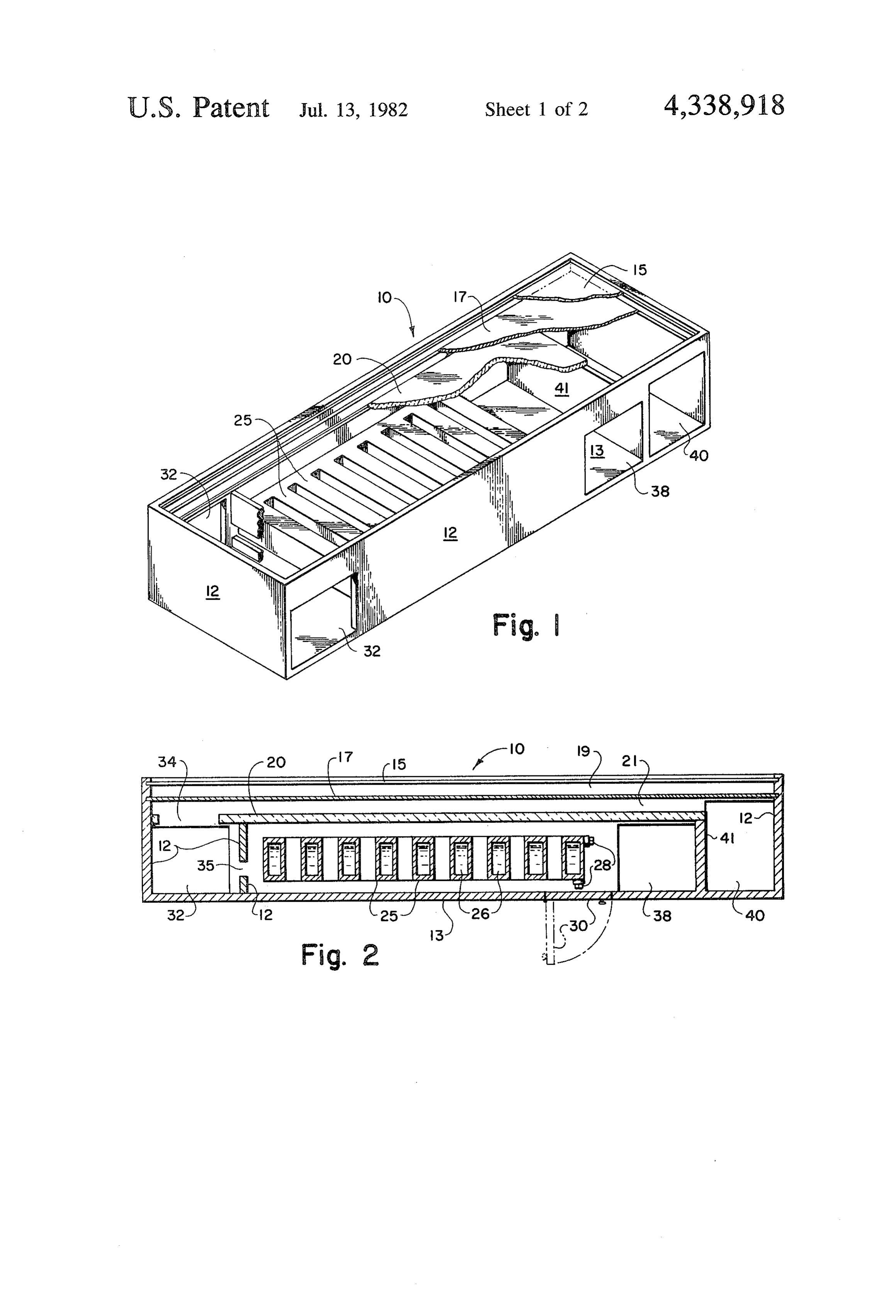
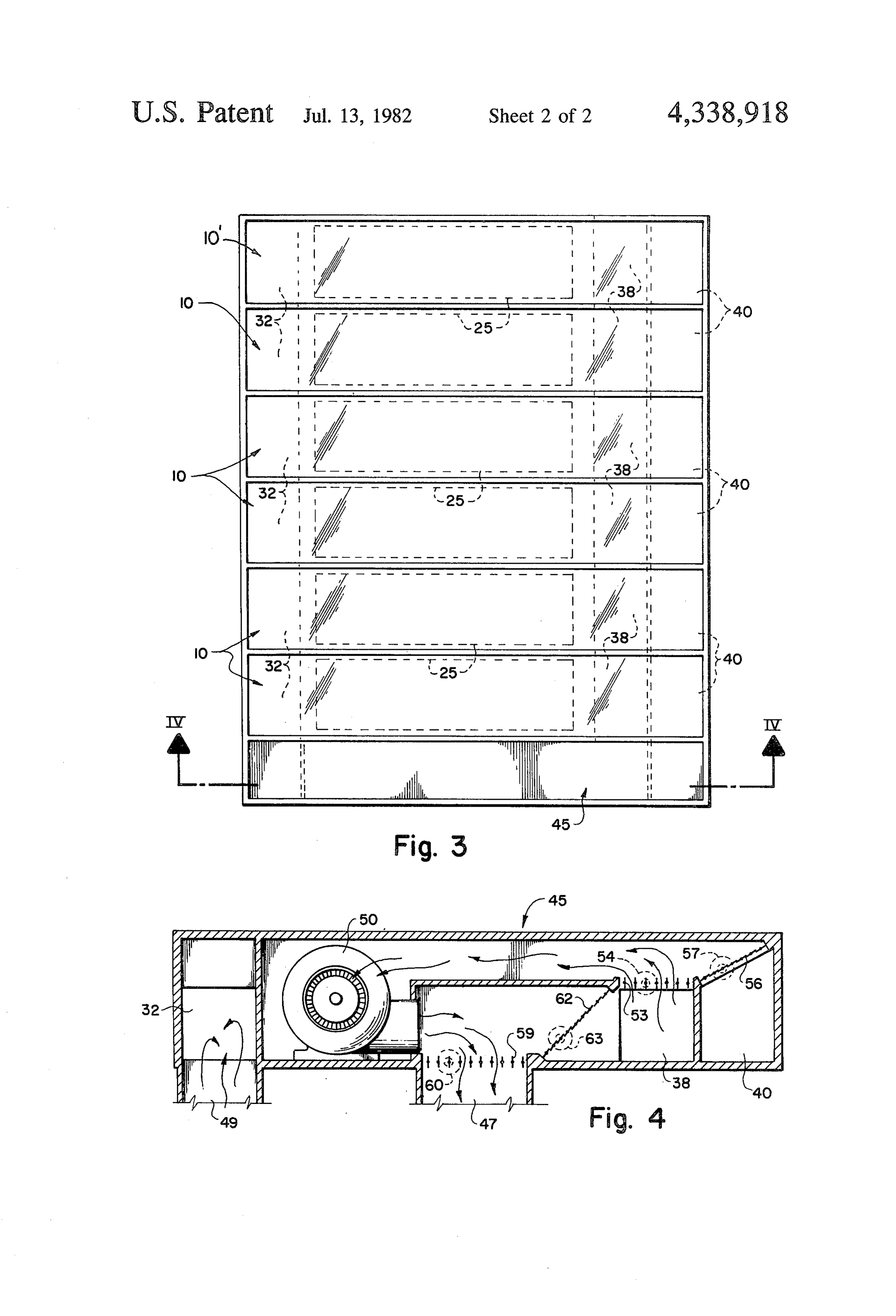
BRIEF DESCRIPTION OF THE DRAWINGS inlet 28. Inlets 28 are preferably oriented so as to be In the drawings: accessible through access door 30 defined in back cover FIG. 1 is a perspective view of a partially cut away, 13.
preferred collector-storage module in accord with the Collector-storage module 10 includes a return air instant invention; duct 32 which is in communication with absorber chan FIG. 2 is a sectioned, side view of the collector-stor- 10 nel 21 through opening 34 and also in communication age module of FIG. 1; with heat reservoir channel 23 to opening 35. Return air FIG. 3 is a top view of a series of the collector-stor duct 32 extends substantially through module 10 except age modules of FIG. 1 in conjunction with a power in the instance of an end module 10' as shown in FIG. 3, module; and in which instance duct 32 extends only through one side FIG. 4 is a sectional view along section line 4-4 of 15 of module 10'. In this manner, return air duct 32 runs the power module shown in FIG. 3. through the length of joined modules 10. Openings 34 DETALED DESCRIPTION OF THE and 35 may be of increasing dimensions along joined INVENTION modules 10 in order to promote relatively equal flow through
Turning now to the drawings, wherein like compo- 20 compensating the modules within large openings 34 and 35 nents are designated by like reference numerals modules 10. Such for the more remote location of certain of throughout the various figures, a typical collector-stor in the art of duct sizing sizing.
is well known and conventional age module for utilizing solar energy for building heat ing is illustrated in FIG. 1 and generally described by 38Modules and 10 and 10' also include heat reservoir duct absorber duct 40 defined by partition 41 in the reference numeral 10. As shown, module 10 which may 25 end portions thereof in a manner similar to that in which form the surface of a wall or roof of a building, includes return air duct 32 is formed side enclosures 12, which may be, for instance, sheet ingly, when a plurality ofasmodules described above. Accord 10 are joined to metal, rafters or other structural members of a building gether with ducts 32,38 and 40 interfacing, as shown in (not shown). Preferably side enclosures 12 are free FIG. 3, and further joined with an end module 10", standing structural units which fit into and support not 30 only module 10 but also lend structural support to the ducts 32, 38, and 40 form a continuous duct system interfacing sections of the building in which module 10 throughout modules 10 and 10'. While ducts 32, 38 and is utilized. Back cover 13 encloses module 12 with side 40 are illustrated as being formed in the side walls of enclosures 12 on five sides. module 10, external ducting may, of course, be em At the open side of module 10, glazing 15, which may 35 ployed. External ducts are useful when modules 10 and 10' are positioned between rafters, thus blocking direct be glass, polymeric or other such material, is supported. connections
Glazing 15 preferably is transparent or translucent to between modules 10 and 10'. relatively short wavelength radiation, i.e., ultraviolet Power unit module 45, as shown in detail in FIG. 4, radiation as is common in solar energy but opaque to abuts the end of the ganged collector storage modules longer wavelength radiation such as infrared radiation 40 10 and 10' as shown in FIG. 3. With reference to FIG. which would be admitted by heated surfaces. This well 4, it is to be noted that power module 45 includes a known phenomenon is commonly referred to as the continuation of return air duct32, heat reservoir duct 38 "greenhouse effect.' Spaced inwardly from but adja and absorber duct 40. Also defined therein are heated cent to glazing 15 is absorber 17, as is particularly well air outlet.47 and return air inlet 49. Heated air outlet 47 illustrated in FIG. 2. Glazing 15 and absorber 17 form 45 communicates directly with a conventional heat supply an insulating void 19 therebetween to minimize heat duct system in a building, and return air inlets 49 simi losses to the environment by conduction through glaz larly interface with conventional cold air return. This ing 15. The insulating effect may be enhanced by utiliz latter aspect is conventional and not specifically illus ing double panes of glazing 15 as is well known. Ab trated.
sorber 17 is preferably black at the side facing glazing 50 Blower 50 is positioned in power unit module 45 and 15, and may include corrugations to serve as wavetraps communicates at the inlet side with heat reservoir duct and induce turbulence to aid in heat transfer to fluid damper 53, operably by servo 54 and absorber duct flowing over the absorber. damper 56, operable by servo 57. Dampers 53 and 56 Divider 20 defines absorber channel 21 between ab may be selectively opened or closed to enable blower 50 sorber 17 and divider 20. Divider 20 is preferably of an 55 to selectively draw heat from heat reservoir 38 and/or insulating material, such as a foamed polymer or wood. absorber duct 40. The outlet of blower 50 communi Heat reservoir channel 23 is defined by, for instance, the cates with heated air outlet damper 59, operably by other side of divider 20 and back cover 13. Channels 21 servo 60 and heat storage mode damper 62, operably by and 23 are adapted to flow a heat transport fluid, prefer servo 63. Accordingly, the outlet from blower 50 may ably air. Hollow heat reservoir 25 is disposed within 60 be selectively routed to heated air outlet 47, and thus to heat reservoir channel 23 and is adapted to contain a a conventional heat supply system.
fluid heat storage medium 26. Heat reservoir 25 may be, The inlet of blower 50 may be selectively connected as illustrated, a multi-legged reservoir, or alternatively to heat reservoir duct 38 and/or absorber duct 40 by of a corrugated design to provide a relatively high sur appropriate positioning of heat reservoir duct damper face area to enclose volume ratio. While heat reservoir 65 53 and absorber duct damper 56. In this manner, heat 25 may be of plastic, or other such material, it is prefera may be supplied to the conventional heating system bly formed of metal such as galvanized steel. Strength from absorber 17, and/or from heat storage reservoir may be provided by attaching heat reservoir 25 to the 25.
Page 6scan →
In the event heat is available at absorber 17 but not a surface of the building in which they are employed. required to heat the subject building, heat storage The more massive heat storage medium, such as water damper 62 may be opened and absorber duct 56 also or a flowable solid, may be added to the otherwise opened. This, with the other dampers closed, will in easily handled modules after the modules are in place, duce a closed route circulation from the back side of 5 and the modules may be directly connected to conven absorber 17, through absorber duct 40, through blower tional heat distribution systems without the complica 50, then through duct 38 to heat storage reservoir 25 tion of remote storage of the heat relative to the collec and, through opening 34, again past the back side of tOr.
absorber 17. In this manner, heat is supplied to heat Although only limited embodiments of the present storage medium 26 to be maintained until required to 10 invention have been illustrated and described, it is antic heat the building.
The following table illustrates the more preferred apparent tovarious ipated that those changes and modifications will be skilled in the art, and that such modes of operation: changes may be made without departing from the scope 15 of the invention as defined by the following claims.
I claim
Dampers
Heat
Reservoir Absorber Heat Air Heat 1. A method for operating a unitary structure for
Duct Duct Outlet Storage absorbing and storing solar energy, the method com
Heat from ab 20 positioning at the outer surface of a building a modu sorber to lar enclosure including glazing transparent to solar heating system Closed Open Open Closed energy at an outer surface thereof, an absorber Heat from ab adjacent the glazing and within the enclosure, and sorber and storage to an empty, self-contained hollow heat reservoir heating system Open Open Open Closed adjacent the absorber and also within the enclo Heat from sure;
storage to structurally securing the modular enclosure to the heating system Open Closed Open Closed
Heat from building;
absorber to storage Closed Open Closed Open filling the heat reservoir with a flowable heat storage 30 media after the module is positioned and structur ally secured to and reinforced by the building;
Power unit module 45 may be positioned in other flowing a heat transfer fluid first over an absorber than the end position by appropriate ducting. Addi surface and then to the heat transfer reservoir to , tional blowers may be provided in larger installations. thus withdraw heat energy from the absorber and From the above description, it would be apparent 35 invest the heat energy in the heat reservoir and that modules 10, 10' and 45 may be conveniently prefab heat storage mechanism therein; and ricated, readily assembled at a building site in place to thereafter flowing a heat transfer fluid over the heat lend structural support to the building. Rather than reservoir and then into the interior of the building providing extensive plumbing and pumps through the to withdraw heat from the heat reservoir and sup building to remote storage, the method and structure ply the stored heat energy to the interior of the described provides for a direct interfacing of the heat building;
collection and storage module with conventional heat whereby heat may be collected and stored in a uni distribution means. If desired, hot water may also be tary modular enclosure supported by the building, provided by interfacing, either directly or through heat which modular enclosure need not support the exchangers, with the heat storage means. While it is 45 weight of the heat storage media until structurally preferred that heated air be employed as the primary supported by the building. heat transfer fluid, hot water may be withdrawn for 2. A method for operating a unitary structure for heating purposes from the reservoir, or merely as a absorbing preheat for domestic hot water. Since it is generally 1 in whichand the storing solar energy as set forth in claim heat storage media comprises water.
contemplated that solar heating systems be sized to SO 3. A method for operating a unitary structure for provide less than the entire heat load during extremely cold periods or cloudy periods, a backup heating system absorbing and storing solar energy as set forth in claim will generally be provided and may, if desired, be incor 1 in4. which the heat transfer fluid is air. A method for operating a unitary structure for porated in the solar collector-storage system described. absorbing
However, such features are essentially conventional 55 1 in whichand storing solar energy as set forth in claim the heat transfer fluid flowing from the ab and well within the skill of the art to provide either sorber to the heat reservoir is diverted to the interior of within the solar collector-storage system as described, or within the conventional heat distribution system. the building to provide direct heating of the interior of Other conventional features, such as means to vent the the building.
absorber in the instance of overheating during, for in 5. A method for operating a unitary modular enclo stance, summer months are contemplated but not specif sure for absorbing and storing solar energy to heat a ically disclosed. A temperature responsive dampler at building, the enclosure including glazing transparent to the volume between the absorber and glazing serves this solar energy at an outer surface of the enclosure, an end. absorber adjacent the glazing and within the structure, In summary, the instant invention provides a method 65 and a self contained hollow heat reservoir containing a and structure whereby integral collector-storage mod heat storage medium therein positioned adjacent the ules may be readily handled during construction, pref absorber and within the enclosure, the method compris erably lending actual structural support to and forming 1ng:
Page 7scan →
absorbing solar energy passing through the glazing at heat reservoir empty, and, after being secured to the the absorber to produce sensible heat; building, the heat storage medium is flowed into the transferring the sensible heat from the absorber to a reservoir, whereby the weight of the modular enclosure heat transfer fluid; is minimum during handling and installation, and pro selectively flowing the heat transfer fluid from the vided with the more dense heat storage medium only absorber to the adjacent heat storage reservoir to after being secured to and supported by the building. invest heat therein in the instance of excess avail 10. A method for operating a unitary, modular enclo able energy, and then back to the absorber, and sure for absorbing and storing solar energy for use in terminating flow of the heat transfer fluid from the heating absorber in the absence of solar energy and initiat 10 least onealayer selected volume, the enclosure including at ing a flow path of heat transfer fluid from the inte an outer surfaceofthereof, glazing transparent to solar energy at an absorber adjacent the glaz rior of the building to the heat storage reservoir to ing and within the enclosure, withdraw sensible heat from the reservoir and then low heat reservoir includingand a self contained, hol flowing the heat transfer fluid to the interior of the storage medium positioned within thea enclosure therein flowable heat and
6. A method for operating a modular enclosure as set adjacent the absorber, the method comprising: forth in claim 5 in which the heat storage medium passing radiant solar energy when available through within the self contained hollow heat reservoir com the glazing and absorbing the solar energy upon prises water and the heat transfer fluid comprises air. the absorber to produce sensible heat; 7. A method for operating a modular enclosure as set 20 transferring the sensible heat from the absorber to a forth in claim 5 in which the heat transfer fluid is flowed heat transfer fluid;
from the back of a plurality of absorbers contained selectively flowing the heat transfer fluid from the within a plurality of similar modular enclosures, absorber to at least one of the heat storage reser through a power unit including fan means and heat voirs and a heating system adapted to provide sen transfer fluid valving means, and from the power unit to 25 sible heat to the selective volume; and a plurality of heat storage reservoirs within the enclo terminating flow of heat transfer fluid from the ab sure, whereby a plurality of modular enclosures may be sorber in the absence of radiant solar energy and interconnected and operated with a single power unit. initiating a flow of heat transfer fluid in the heating 8. A method for operating a modular enclosure as set system from the volume to be heated to the heat forth in claim 5 in which the modular enclosure is se 30 storage reservoir and back to the volume to be cured to the external surface of a building. heated to withdraw sensible heat from the reser 9. A method for operating a modular enclosure as set voir and provide such heat to the volume to be forth in claim 8 in which the modular enclosure is se heated.
cured to the building with the self contained hollow E SK K It
Provenance
- Collection
- Patents citing this work
- Pages
- 7
- Method
- pdftotext (the PDF's own text layer) + pdftoppm 300dpi page scans
- Patent office record
- patents.google.com →
- Source
- Google Patents citing-documents table
- Assignee
- Thomas W. O'Rourke
- Published
- 1982-07-13
- Transcribed from
- patentimages.storage.googleapis.com →