

patent · US4359043A
Roofing member for collecting solar energy
16 November 1982
Text
Page 1bibliographic recordscan →
United States Patent (19)
Dominique et al.
(54) ROOFING MEMBER FOR COLLECTING
SOLAR ENERGY
Inventors: Gazel Dominique, Residence
Cormontaigne 5/7; Huges Dailliez, 283, rue Nationale, both of a Lille
(Nord); Denis Consigny, La Pierre
Plantee, a Rousson (Gard), all of
France
30 Foreign Application Priority Data
Apr. 27, 1979 FR France ................................ 79 11526
51 Int. Cl. ................................................. F24, 3/02 52 U.S. C. .................................... 126/444; 126/450;
2,213,894 9/1940 Barry ................................... 126/443 2,489,751 1 1/1949 Candler ............................... 26/47 3,981,294 9/1976 Deminet et al. ..., 26/449 4,128,095 12/1978 Oren et al. .......................... 126/449
4,137,903 2/1979 Annett ...... ... 126/443 4,141,338 2/1979 Lof ...................................... 126/44 4,186,725 2/1980 Schwartz ..... 126/443 4,205,655 6/1980 Hunt .................................... 126/443
ataeataezzzzzzeezeaezaleaza
snSnassssssss Sna
FOREIGN PATENT DOCUMENTS
Primary Examiner-Daniel J. O'Connor
Attorney, Agent, or Firm-Robert E. Burns; Emmanuel J. Lobato; Bruce L. Adams
A roofing member for collecting solar energy defines an external shape and has dimensions similar to traditional roofing means such as tiles or slates. The roofing mem ber comprises at least one transparent wall with a closed cavity below this wall, and a dark area in contact with the cavity below said wall. First and second comple mentary connecting means are located respectively in an area of a side of the member intended to be placed at an upper level and in an area of a side of the member
intended to be placed at a lower level. In this way a mechanical connection can be made simultaneously between the first complementary connecting means of a second similar member superimposed by the said area of the side intended to be lowermost and the second com plementary connecting means of the member simulta neous therewith a sealed interconnection of the respec tive cavities of these two members can be made in order
to allow the circulation of a heat-carrying fluid from one member to the other.
15 Claims, 6 Drawing Figures
Drawings
Page 2drawing sheetscan →
Page 3drawing sheetscan →
Page 4scan →
manner as traditional roofing members and an arrange
ROOFING MEMBER FOR COLLECTING SOLAR ment of collector members according to the invention ENERGY may be put in position on a roof by a roofer using tradi tional methods, without any special precaution linked in
The present invention relates to a roofing member for particular with the necessity of interconnecting the a roof, which member is intended to collect solar en inner areas of the collectors.
ergy. It is thus possible to combine on the same roof, a In their best known form, solar collectors are in the varying number of collectors according to the invention form of panels of varying size, inside which one creates which are connected in series in order to constitute, a glass-house effect used for heating a heat-carrying O whilst being perfectly integrated in the roof, a bank of fluid which is subsequently used generally for heating collectors having equivalent performances to those of a purposes. traditional collector panel of large size, whatever this Since these panels are water-tight, it has been consid Sze.
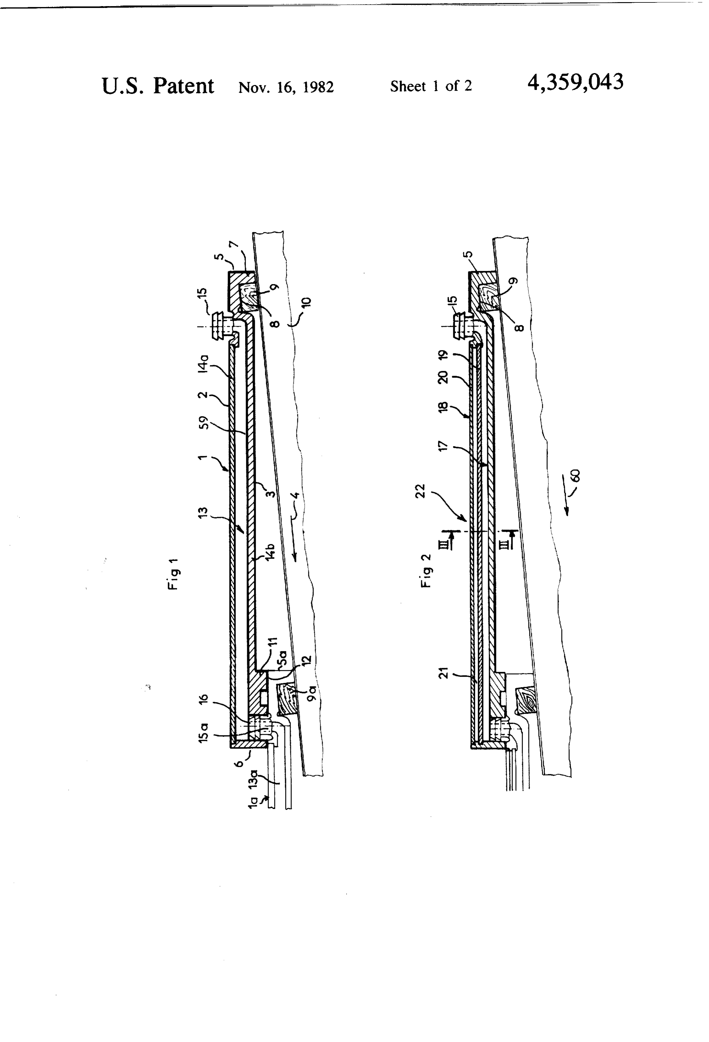
ered juxtaposing a plurality thereof by connecting them The roofing member for a roof according to the in by water-tight seals, in order to form roofing members 15 vention, intended to collect solar energy and compris replacing traditional roofing members such as tiles and ing at least one transparent wall, a closed cavity below slates on a roof. the transparent wall, a dark area in contact with the This solution seemed advantageous in that it made the cavity, below the transparent wall, is characterised in roofs lighter, but the aesthetic result was far from satis that externally it has the shape and dimensions of a factory and above all, on the one hand the connection of 20 traditional roofing member such as a tile or slate, or of the collectors to each other in order to allow the circu an arrangement of such members and in that it com lation of the heat carrying fluid and on the other hand prises complementary connecting means respectively in the water-tight connection of these panels to traditional an area of its upper side intended to be placed at an roofing members such as tiles or slates covering other upper level and in an area of its lower side intended to areas of the roof were carried out more or less by rule 25 be placed at a lower level, in order to ensure a mechani of thumb, with very uncertain results in particular as cal connection simultaneously between a member su regards the seal in the region of the connection. perimposed by the said area of its lower side on the said Furthermore, the attachment of collector panels to area of the upper side of a second similar member and the timber could not take place in the same manner as the sealed interconnection of the respective cavities of the connection to the latter of traditional roofing mem 30 these two members in order to allow the circulation of bers such as tiles or slates, which most frequently neces a heat-carrying fluid from one to the other. sitated a special design of the timber in its regions in The invention will be better understood on referring tended to receive solar panels; in particular, it seemed to the ensuing description, relating to non-limiting em very difficult, apart from chance solutions, to locate the bodiments, as well as to the accompanying drawings members forming solar energy collectors on existing 35 which form an integral part of this description. timberwork, by partly replacing the tiles or slates ini FIG. 1 is a view of a first example of a roofing mem tially provided. ber according to the invention, seen in section through In fact, it is apparent that with their present design, a vertical plane parallel to the direction of the slope of solar energy collectors are unsuitable for use as roofing the roof.
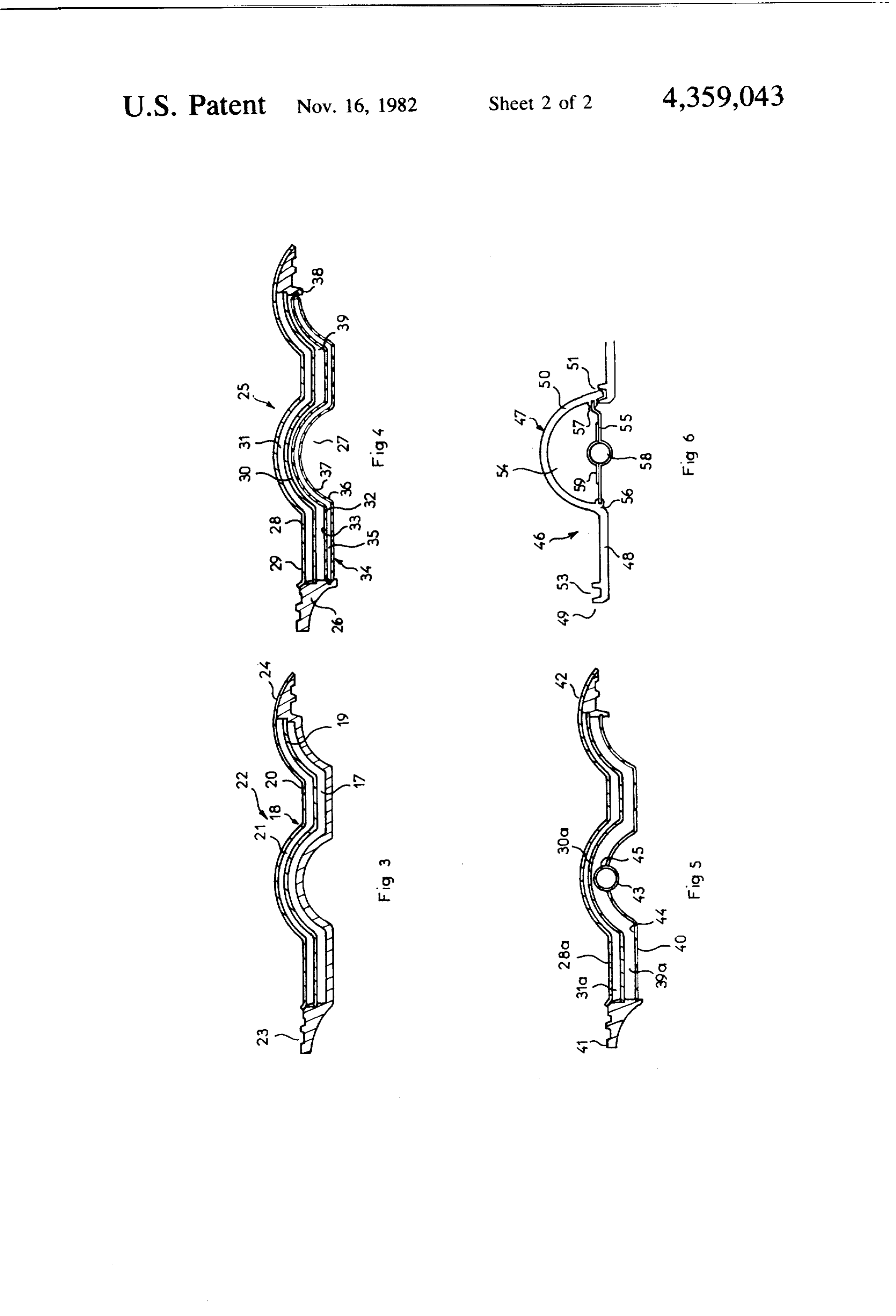
members and the purpose of the present invention is to FIG. 2 is a similar view of a second example of a propose a device which is simultaneously a solar collec roofing member according to the invention. tor and a roofing member and which is perfectly suited FIG. 3 is a view in section through the plane III-III to both of these functions, of FIG, 2.
To this end, the invention proposes a solar collector FIGS. 4 to 6 show three variations of a tile according whereof the external shape is that of a traditional roof 43 to the invention, in views similar to that of FIG. 3. ing member such as a tile or slate, or of an arrangement FIGS. 1 to 5 correspond to the case of a roofing of these members assembled traditionally and which member according to the invention having the known may consequently overlap such members in a tradi external shape of a flat tile and FIG. 6 to the case of a tional manner and be fixed in the same way as the latter ridge tile, but a man skilled in the art will naturally be to timberwork. This provides the possibility of produc able to produce a member of this type having the exter ing roofs on traditional timberwork, in particular by nal shape of other known roofing members, such as for replacing an existing traditional roof, in which tradi example tiles of other shapes or slates, without diverg tional roofing members such as tiles and slates are mixed ing from the scope of the invention. with members according to the invention, with an aes If particular reference is made to FIG. 1, where a thetic and technical result, from the point of view of 55 roofing member according to the invention is drawn in water-tightness, similar to that obtained when con full line and part of a second member according to the structing a traditional roof from tiles or slates. invention is drawn in thin line, which member is con In order that the laying of the members according to nected to the first and located at a level directly below the invention is carried out in a traditional manner, the level of the latter in the direction of the slope of the means are provided for ensuring an automatic mutual roof, it will be seen that a member 1 according to the connection of the members which are placed partly one invention in this case comprises a front side 2 and a back above the other in a scalloped arrangement, in order to side 3 which are substantially flat and parallel over the ensure simultaneously a mutual mechanical connection major part of their surface. In a plane parallel to the of the members, ensuring the mutual interconnection sides 2 and 3, the member having a rectangular shape whilst complementing their connection to the timber defined by two longitudinal lateral edges intended to be work and a connection of the area provided inside each orientated parallel to the direction of the slope of the member for the circulation of heat-carrying fluid. The roof 4 and an upper end portion 5 and a lower end wall members according to the invention are laid in the same 6, intended to be orientated at right angles to this direc 5 tion 4 in order to define respectively the upper edge and colour is naturally chosen according to the normal co the lower edge of the member. The sides 2 and 3 con louring of this traditional roofing member. prise, in the immediate vicinity of the longitudinal edges To facilitate filling of the cavity 13 with heat-carry of the member, a similar relief which compliments that ing fluid, which is generally liquid and the circulation of comprised by traditional tiles in this region, in order to this fluid between the cavity 13 and similar cavities of facilitate their mutual lateral interengagement (this adjacent roofing members and between these cavities known relief in itself has not been shown). Further and the utilisation circuit, complementary connection more, in the immediate vicinity of the upper edge of the means, respectively 15 and 16 have been provided in the end portion 5, over the entire lateral extent of the latter, front side the upper end portion 5 of the member and in the back side 3 comprises a projecting rim 7 connected O the back side 12 of the heel portion 11, in the vicinity of to the remainder of the side 3 by a groove 8 also extend the lower end wall 6 of the member, which means 15 ing over the entire lateral extent of the upper end por and 16 are furthermore able to provide mechanical tion 5, in order to fit on a batten 9 fixed in a traditional connection of the members according to the invention manner to the rafters 10 of the timberwork, at right which are adjacent each other in the direction of the angles to the direction of the slope 4, in the manner of a 15 slope 4.
traditional tile. In the vicinity of the lower end wall 6, The lower connecting means 16 in this case consist of over the entire length of the latter, the back side 3 com a cylindrical orifice, the axis of which is perpendicular prises a projecting heel portion 11, whereof the lower to the side 12, which opens on the one hand into the side 12, parallel to the remainder of the side 3, is able to cavity 13 in the immediate vicinity of the edge of the rest on the front side the upper end portion 5a of a 20 latter closest to the lower end wall 6 of the member and member 1a according to the invention located at a level on the other hand into the side 12 of the heel portion 11, directly below that of the member 1, taking into ac i.e. into the back part of the lower side of the member 1 count the direction of the slope 4, in a region of this which is able to be placed on top of the front part of the front side located in the immediate vicinity of the upper upper end portion 5a of the member 1a located at a edge of the upper end portion 5a of this member 1a. 25 directly lower level.
Thus, the member 1 according to the invention fits The means 15 in turn consist of a tubular conduit laterally with other similar members or with traditional projecting above the front side 2 of the upper end por tiles in the manner in which these traditional tiles are tion 5 of the member and opening into the cavity 13 in fitted laterally, it rests by an area of its back side located the region of the latter closest to the upper end portion in the vicinity of its lower edge on an area of the front 30 5 of. In its region projecting above the side 2, the tubu side of the member immediately below located in the lar conduit has a shape of revolution about an axis per immediate vicinity of the upper edge of this member, pendicular to the general plane of the side 2 with an like traditional tiles and it fits like these traditional tiles outer diameter similar to the inner diameter of the ori on battens 9, to which it may be fixed in a traditional fice 16, the means 15 and 16 being disposed respectively manner for example by nailing (not shown). 35 on the upper side 2 and below the lower side 12 of the Internally, below the major part of its front side 2, the member so that the means 16 of the member 1 fit auto member 1 according to the invention comprises a sealed matically on the means 15a of the member la located at cavity 13 defined towards front side 2 by a rigid trans a directly lower level, which means 15a are identical to parent wall 14a consisting of glass, plastics material or the means 15, when the member 1a is correctly fitted on other transparent material, in which case the term 40 the batten 9a of the timberwork located at a level di "transparent material” is generally understood to mean rectly lower than that of the batten 9 and that the mem a material through which incident solar radiation is able ber 1 is fitted on this batten 9. In view of the fact that the to pass. The cavity 13 is furthermore defined by a shell inner diameter of the orifice 16 is similar to the outer 14b of any rigid material such as plastics material, glass, diameter of the projecting region of the means 15a concrete, terra cotta etc., which in particular defines the 45 (identical to the means 15), it is easy to ensure a water back side 3 of the member, its lateral edges, its upper tight connection between the inner periphery of the end portion 5 with the rim 7 and the groove 8 and its orifice 16 and the outer periphery of the projecting lower end wall and the heel portion 11. The shell 14b region of the means 15a, either by interposing a sealing furthermore defines the base 59 of the cavity 13, which material, or directly if one adopts the arrangement illus is substantially flat and parallel to the sides 2 and 3. 50 trated in which the projecting region of the means 15 or The cavity 13 is able to receive internally a heat-car 15a comprises outer annular teeth whereof the maxi rying fluid which is able to convey to the point of use, mum diameter is very slightly greater than the inner the energy collected by the member, which for this diameter of the orifice 16 and in which at least the purpose comprises, in an area located below a maximum means 15 are made from an elastically deformable mate of the transparent plate 2, inside the cavity 13, an area of 55 rial such as a plastics material, so that the force fitting of dark colour. This area may be constituted by the base 59 the means 16 on the means 15a results in a sealed con of the cavity 13, which is coloured throughout its mass nection and mutual interengagement.
or painted in a dark colour, or by the heat-carrying fluid Preferably, in order to ensure a flow which is as regu itself containing dark pigments in solution or suspension lar as possible between the cavity 13 and the similar or, more generally, substances facilitating the collection 60 cavity 13a of the member 1a, the projection formed by of solar energy in the form of calorific energy. Prefera the conduit 15a (or 15) above the upper side of the bly, the dark colour is chosen to match the colour of member is equal to the distance separating the side 12 of traditional tiles which may border the members accord the heel portion 11 from the base 59 of the cavity 13, so ing to the invention, in order to ensure that the roof has that the upper end of the conduit 15a is flush with the a homogeneous appearance close to that of a roof con 65 base 15 of the cavity 13.
structed throughout from traditional tiles. When the Naturally, the connecting means 15 and 16 used in exterior of the member according to the invention is in this case for connecting two members according to the the shape of a roofing member other than a tile, the dark invention, which are adjacent each other in the direc 6 tion of the slope 4, may also be used to ensure the con colour, preferably matching the colour of traditional nection to the utilisation circuit at the top and bottom of roofing members with which it is desired to mix the the slope (not shown). members according to the invention. In one variation of the invention, in which the men In the case of FIG. 4, the roofing member 25 is sub ber is intended to simulate a traditional roofing member, stantially of the same outer shape as the members illus intended to be connected in staggered arrangement to trated in FIGS. 1 to 3, in particular with a view to its adjacent members, by being superimposed over two connection towards the top, towards the bottom and similar members located at a directly lower level, one laterally to other adjacent similar members or to tradi could envisage a connection of each of the members to tional flat tiles.
each of the members directly therebelow, through the O Nevertheless, its periphery designed with a view to intermediary of means similar to the means 16 and 15 this connection is defined by a frame 26 open right thus provided respectively in a number equal to two or through on the major part of its central area 27 in which multiples of two. When the members according to the are superimposed a first transparent wall 28, which is invention are intended to be placed in rows parallel to water-tight and connected in a sealed manner to the the direction of the slope, in the manner of traditional 5 periphery of the frame 26, which wall defines the upper tiles and as is illustrated, one could naturally also pro side 29 of the member and a second transparent wall 30, vide a plurality of means 15 and means 16 respectively which is also water-tight and connected in a sealed for ensuring multiple mechanical connection and circu manner to the frame 26 by its periphery, which wall 30 lation of the heat-carrying fluid. is located behind the wall 28 at a distance from the latter Naturally one could provide methods of connection such that the two walls define a sealed chamber 31 other than those which have been described and illus therebetween, which chamber can be placed under trated and in particular means 16 projecting below the partial vacuum or may contain a gas or liquid. lower side of the member, which are able to fit in upper A sealed wall 32 is disposed behind the wall 30, recessed means. Whatever the embodiment chosen, the which wall 32 is opaque and facing the walls 30 and 28, complementary connecting means will preferably be 25 has a side 33 of dark colouring, chosen according to the constructed so that although they ensure effective con colour of the traditional roofing members with which nection as regards the seal and mechanical strength, the member 25 is intended to be combined, possibly on they have a certain flexibility facilitating a movement of the same roof. This wall 32 in fact constitutes the upper the assembled members, due to expansion. wall of a flat, sealed chamber 34, defining internally a In the variation illustrated in FIGS. 2 and 3, the men 30 cavity 35 which is able to receive a heat-carrying fluid ber 22 according to the invention has a shape similar to and to be connected to similar cavities of members that of the member 1 and, like the latter, comprises a similar to the member 25, as in the case of the preceding cavity 17 on its inside, which cavity can be connected in examples, in order to allow the circulation of the heat a sealed manner to corresponding cavities of similar carrying fluid from one cavity 35 to the other. To this members located respectively at an upper level and at a 35 end, it is possible to use the same means as in the case of lower level, taking into account the direction 60 of the the examples illustrated in FIGS. 1 to 3, or even a varia slope of the roof, by means also ensuring a mechanical tion according to which the member 25 comprises, connection of these members. projecting respectively above its upper side in particu In contrast to the cavity 13 of the member 1, the lar defined by the transparent wall 28 and below its cavity 17 is not in direct contact with the transparent lower side in particular defined by the lower side 36 of front wall 20, similar to the transparent wall 14, defining the base 37 of the chamber 34, respectively in its area the major part of the front side 18 of the member, but a intended to be placed at an upper level and in its area second wall 19 is interposed between the cavity 17 and intended to be placed at a lower level, taking into ac the wall 20, which wall 19 is parallel to the wall 20 at a count the slope of the roof, a conduit which is able to be certain distance from the latter in order to define there 45 connected automatically to the other conduit of a mem with a sealed chamber 21 which may contain a liquid or ber directly below or directly above, when these mem a gas, or in which it is possible to establish a partial bers are put in position on the timberwork of the roof, a vacuum. When the member is exposed to solar radia sleeve comprising internally transverse dimensions simi tion, a glass-house effect is created in the chamber 21, lar to the outer transverse dimensions of the two con which makes it possible to increase the quantity of calo SO duits being able to be provided for ensuring their sealed rific energy transmitted to the heat-carrying fluid circu connection. As in the case of the enbodiment illustrated lating in the cavity 17, which is filled throughout with in FIGS. 1 to 3, toothing of the conduits combined with this heat-carrying fluid like the cavity 13 of the member elasticity of the latter and/or of the sleeve may be pro 1 and internally comprises a region of dark colour de vided in order to ensure a perfectly sealed connection fined by suitable colouration of its walls or by pigments 55 and, simultaneously, a mechanical inter-connection of contained in the heat-carrying fluid. the members.
FIG. 3 shows the complementary shape of the two On its periphery, which coincides with that of its longitudinal edges 23 and 24 of the member 22, which upper side 33, the flat chamber 34 is connected in a edges are intended to be orientated parallel to the direc sealed manner to a rim 38 on the underside of the frame tion of the slope of the roof, in order to facilitate mutual 26, so that the walls 30 and 32 define a sealed chamber lateral engagement of the members. 39 therebetween, which, like the chamber 31, can be FIGS. 4 to 6 illustrate three variations in which the placed under partial vacuum or can be filled with a gas cavity able to receive the heat-carrying fluid is not or liquid. This chamber 39 produces a glass-house effect defined directly by a transparent wall, but in manner complementing the glass-house effect established in the known per se by an opaque wall, for example a metal chamber 31, and like the latter not being in contact with wall, located at a distance behind a transparent wall the outer air, which makes it possible to considerably which defines the front side of the member and com improve the efficiency of the collector. However, it will prising, facing this transparent wall, a side having a dark also be noted that this collector could be constructed in 7 a simpler form, by eliminating the intermediate trans closes in a sealed manner so that a glass-house effect is parent plate 30. established at this point.
FIG. 5 illustrates an embodiment similar to that of Passing through the wall 55, over its entire length and FIG. 4, since it differs from the latter solely in the parallel to the edges 49 and 51 of the member is a con method of constructing the means defining the cavity 5 duit 58 which at any point is comparable with the con for the circulation of the heat-carrying fluid. duit 43 of the member illustrated in FIG. 5, in particular In fact, in the case of FIG. 5, the chamber 34 of the as regards its possibilities of connection to the similar embodiment of FIG. 4 is replaced by a single opaque conduit of the members respectively directly below and wall 40 located at a distance behind a transparent wall directly above, in order to establish a circulation of the 30a similar to the wall 30, itself located at a distance O heat-carrying fluid. In order to ensure maximum trans behind a transparent wall 28a similar to the wall 28, the the mission to the heat-carrying fluid of the heat present in walls 40 and 30a defining therebetween a sealed cham of the cavity 54 by a glass-house effect, the upper side 59 ber 39a similar to the chamber 39 and the walls 30a and wall 55 and of the conduit 58 has a dark colour preferably 28a defining therebetween a sealed chamber 31a similar 15 tiles, the area reproducing the colour of traditional ridge to the chamber 31. In a central area parallel to the longi bly being of this 48 of the transparent wall 47 also prefera tudinal edges 41 and 42 of the member, i.e. parallel to colour.
In the example the direction of the slope when this member is fixed to through the wall 55 at illustrated, the conduit 58 passes roofing timber, the plate 40 includes a sealed tubular the areas of the wall 47 a point which is midway between member 43 which is able to receive the heat-carrying 20 the corresponding respectively to fluid in its inside and to be connected, like the chamber part 50 to the part 48, but and edge 51 of the member to the connection of the naturally one could provide 34 of the member 25 illustrated in FIG. 4, respectively other positions. Furthermore, although the wall 55 has by its upper part to the lower part of the similar conduit been shown flat, the latter could of the member immediately thereabove and by its lower be curved reproducing the curvealso of be constructed to the part 50 of the part to the upper part of the similar conduit of the mem 25 transparent wall 47, so that each of the areas ber immediately therebelow. In order to ensure the 55 is placed substantially at the same distanceoffrom the wall the transmission of heat produced by the glass-house effect wall 47 in order that solar radiation may reach the dif in the chambers 31a and 39a to the heat-carrying fluid ferent areas of the dark side 59, in an identical manner, circulating in the conduit 43, the upper side 44 of the throughout the day.
plate 40 and the upper side 45 of the conduit 43 facing According to another embodiment, one could also the transparent plate 30a, have a dark colouring prefera provide below virtually the entire transparent wall 47, bly matching that of traditional roofing members with i.e. also below the part 48 of the latter, a wall similar to which the members according to the invention may be the wall 55 and defining therewith a sealed chamber in combined. which a glass-house effect is established. Naturally, as in the case of the embodiment described 35 In another embodiment of the invention, the connec previously, this member could be constructed in a sim tion of the cavities able to receive internally a heat-car plified form by eliminating the transparent wall 30a. rying fluid and to convey the latter, may be carried out FIG. 6 shows a member according to the invention by fitting connecting members parallel to the upper side constructed according to a technique similar to that of of the tile. This connection thus varies from that de the member illustrated in FIG. 5, apart from the fact 40 scribed with reference to FIGS. 1 and 2, in which the that externally it is in the shape of a ridge tile. Naturally, members 15 and 16 are substantially perpendicular to members according to the invention belonging to any the upper surface of the tile.
one of the embodiments illustrated in FIGS. 1 to 5 could In the case of members parallel to this upper surface, be constructed with this external shape. the connection is carried out below the tile by the inter In the case of the embodiment of FIG. 6, the member 45 engagement of a male conduit and a female sleeve. The 46 according to the invention comprises a transparent outer diameter of the male conduit is substantially equal wall 47 having the general shape of a traditional ridge to the inner diameter of the female sleeve, which may tile, i.e. comprising a flat region 48 whereof one of the also comprise an appropriate device and for example an edges defines a longitudinal edge 49 of the member, O-ring in order to make this joint tight. This arrange which is intended to be orientated in the direction of the 50 ment enables the various roofing members to expand. slope and an area 50 enlarged in an upwards direction On account of this arrangement, it is also possible to fit adjoining the area 48 at a point approximately along half these various members with less accuracy compared the width of the member and defining the second longi with the fitting accuracy of traditional roofs. The ex tudinal edge 51 of the latter. As in the case of a tradi pansion and inaccuracy in the fitting will result in slid tional tile of this type, the upper side of the member 55 ing of the male connecting member in the female con comprises, in the vicinity of the edge 49 of the latter, a necting member, their tight coupling being ensured for groove 53 able to receive the edge of a similar adjacent example by the O-ring. This O-ring will preferably be member corresponding to the edge 51, or the corre placed in the female sleeve, with the aim of preventing sponding edge of a traditional ridge tile (a connection of any wear on the latter during the operations of handling this type is shown in the right-hand part of FIG. 6, 60 the various connecting members, where the edge of another member is drawn in thin Naturally, one could envisage numerous variations of line). the roofing member according to the invention without In the region of the area 50, the lower side of the diverging from the scope of the latter. In particular, one transparent wall 47 defines a cavity 54 which a sealed could envisage the construction of a member according wall 55, located as an extension of the wall 48 and fixed 65 to the invention with the external shape of an arrange for example by the engagement of its periphery on suit ment of traditional roofing members such as tiles or able counterparts such as 56 and 57 comprised by the slates, this member being just as able to integrate with area 50 in the vicinity of the back side of the wall 47, traditional members as an individual member described 8 above, but with the additional advantage of being able 3. A roofing construction according to claim 2, in to be laid quicker. which said tubular conduit is of elastic deformable ma What is claimed is: terial and has annular teeth of which the maximum 1. A roofing construction for collecting solar energy diameter is slightly greater than the internal diameter of comprising a multiplicity of like roofing members hav 5 said orifice.
ing externally the shape and dimensions of traditional which 4. A roofing construction according to claim 1, in roofing tiles, said members being assembled in tradi transparent said cavity comprises the space between said tional manner with lateral edges of laterally adjacent front wall and said opaque back wall. roofing members overlapping and with lower edges of 10 which 5. A roofing construction according to claim 1, in upper roofing members overlapping upper edges of O. the inner face of said back wall is of a dark col downwardly adjacent roofing members, each of said 6. A roofing construction according to claim 1, in roofing members comprising a shell of opaque moldable which the heat-carrying fluid is of a dark colour, material having a back wall and opposite side walls, a lower end wall and an upper end portion projecting which a roofing partition construction according to claim 1, in is interposed between said transparent forwardly from said back wall to form a frame for re front wall and opaque back wall, to form said heat-car ceiving a front wall, a transparent front wall received in rying fluid cavity between said partition and said back said frame and sealed to said side walls, lower end wall wall and a sealed chamber between said front wall and and upper end portion, said transparent front wall being said partition.
spaced forwardly from said back wall to provide there 20 8. A roofing construction according to claim 7, in between a heat-carrying fluid cavity, said upper end which said partition is transparent. portion extending longitudinally beyond said transpar 9. A roofing construction according to claim 8, in ent front wall and lying under an upwardly adjacent which a second partition is interposed between said roofing member, said upper end portion having in its transparent partition and said back wall to provide a back a channel to receive a roof support member and in 25 second sealed chamber between said partitions. its front side a first fluid-conducting coupling means 10. A roofing construction according to claims 9 in having a passage communicating with said cavity, said which said second partition is opaque and has a dark back wall having in a lower end portion which overlies coloured front face.
an upper end portion of a downwardly adjacent roofing 11. A roofing construction according to claim 7, in member a second fluid-conducting coupling means 30 which said sealed chamber contains a gas. communicating with said cavity and adapted to interfit 12. A roofing construction according to claim 7, in with said first coupling means of said downwardly adja which said sealed chamber contains a liquid. cent roofing member to interconnect adjacent roofing 13. A roofing construction according to claim 7, in members mechanically and to interconnect fluid cavi which said sealed chamber is under partial vacuum. ties of adjacent roofing members to provide for circula 35 14. A roofing construction according to claim 1, in tion of heat-carrying fluid from one roofing member to which said heat-carrying fluid cavity comprises a sealed another. tubular member incorporated with said back wall. 2. A roofing construction according to claim 1, in 15. A roofing construction according to claim 14, in which one of said interfitting coupling means is a female which a transparent partition is interposed between and coupling means comprising an orifice opening into said spaced from said front wall and said back wall to pro cavity and the other of said interfitting coupling means vide a first sealed chamber between said front wall and is a male coupling means comprising a projecting tubu said partition and a second sealed chamber between said lar conduit having external transverse dimensions sini partition and said back wall. h lar to the internal transverse dimensions of said orifice.
Provenance
- Collection
- Patents citing this work
- Pages
- 8
- Method
- pdftotext (the PDF's own text layer) + pdftoppm 300dpi page scans
- Patent office record
- patents.google.com →
- Source
- Google Patents citing-documents table
- Assignee
- Gazel Dominique
- Published
- 1982-11-16
- Transcribed from
- patentimages.storage.googleapis.com →