

patent · US4364374A
Heat-absorbent panel for solar energy and sloping roof composed of such panels
21 December 1982
Text
Page 1bibliographic recordscan →
United States Patent (19)
Brazzola
HEAT-ABSORBENT PANEL FOR SOLAR
ENERGY AND SLOPING ROOF COMPOSED
OF SUCH PANELS
Inventor: Luigi Brazzola, Castel San Pietro,
Switzerland Assignee: Elioform AG, Triesen, Liechtenstein
(30) Foreign Application Priority Data
Jan. 31, 1979 CH Switzerland ........................... 911/79 Jan. 4, 1980 (CH) Switzerland ............................. 22/80 Int. Cl. ..... - - - - - - - - - - - - - - - - - - - - - - - - - F24J 3/02
52 U.S. Cl. ............................. 126/442; 126/DIG. 2;
4,136,670 1/1979 Davis .................................. 126/450 4,138,991 2/1979 Lorenz ................................ 126/450
FOREIGN PATENT DOCUMENTS
Primary Examiner-Carroll B. Dority, Jr.
Attorney, Agent, or Firm-Young & Thompson
A panel that absorbs solar energy is emplaced as a con ventional inclined roof tile with an appearance compa rable to that of a tile roof, and comprises a metallic or non-metallic tile which has at least one raised portion (4) that collects heat. A seat is provided for a metallic tube (5) through which flows the fluid to be heated. A transparent cap (7) covers, insulates and protects the raised portion (4) of the tile and the tube. The tile has on its upper surface protuberances (9) connected by con duits (10) permitting circulation of the air contained therein toward the raised collector portion (4) which directly absorbs the solar heat.
4 Claims, 6 Drawing Figures
Drawings
Page 2drawing sheetscan →
Page 3drawing sheetscan →
Page 4scan →
berances 9 which project upwardly, of various forms
HEAT-ABSORBENT PANEL FOR SOLAR ENERGY but preferably pyramidal, truncated conical or cupola AND SLOPING ROOF COMPOSED OF SUCH shaped, serving to collect solar energy while always PANELS presenting at least one of their faces oriented in the optimum position relative to the sunrays and serving as
The present invention relates to heat absorbent panels a support for personnel who must walk on the roof, as for solar energy and a sloping roof composed of such well as to retain snow.
panels. The recesses below the protuberances are closed at At present, the panels used on roofs to collect solar their bottom and are connected with each other and energy for heating are generally comprised of a back 10 with the recess beneath the raised portion by means of ground that is black and absorbs heat, an intermediate conduits 10 in which air circulates, thus transporting the compartment and an insulating and protective window heat absorbed in the region of the protuberances toward or glass fixed to the edges and projecting from the back the raised portion 4 and the tube 5. ground. The tubes in which the liquid to be heated The conduits create on their upper surfaces reliefs circulates are disposed in the intermediate compart 15 which serve to prevent the longitudinal displacement of ent.
the transparent cap.
Such panels are subjected to severe thermal stresses The tile is disposed on a thermally-insulating panel and require considerable maintenance. Moreover, over which is secured to a flat surface resting on the struc a long period of time, they do not ensure complete ture carrying watertightness of the roof and, from an aesthetic stand 20 through eyelettheholesroof. The tile is nailed to this surface which permit expansion and con point, they are noticeably different from a roof of con traction and removal of ventional tiles, creating reflections and undesirable vi to cover a sloping roof the tile. It is possible in this way brations, and are difficult to emplace and replace. More rable to that of an ordinaryanroof with aesthetic effect compa covered with tradi over, for large surfaces, the cost of known panels is high. 25 tional tiles. In the raised portion, which because of the The panel according to the invention is characterized superposition of the edges of the tile is continuous from in that it comprises a metallic or non-metallic tile, pref the summit to the base of the incline of the roof, is erably blackened, having preferably at least one raised secured the tube which is covered by the transparent heat-collecting portion, in which may be provided the Cap.
seat for a metallic tube traversed by the liquid to be 30 The tube 5 is retained inposition by an annular clip 6 heated. A transparent cap is provided as a cover, to comprising a spring which permits the emplacement or removal of the tube 5 by simple manual pressure or insulate and protect the raised portion of the tile and the traction.
tube, the tile presenting on its exposed face one or more protuberances each forming an inwardly-opening cav At the upper and lower ends of the incline of the roof, ity interconnected by conduits permitting the circula 35 the tubes 5 are connected to a collector tube (not tion of air contained therein so as to transport the heat shown) which thus integrates all the roof covering in toward the raised portions of the collector. the usual heating equipment for solar energy. These and other features of the invention will become To improve heat absorption and to reduce produc apparent from a consideration of the accompanying tion costs, it is preferred that the tile according to the drawings, in which: 40 present invention be made of glass, ceramic, asbestos FIGS. 1, 1a and 2 show by way of example three cement agglomerate, or synthetic resin.
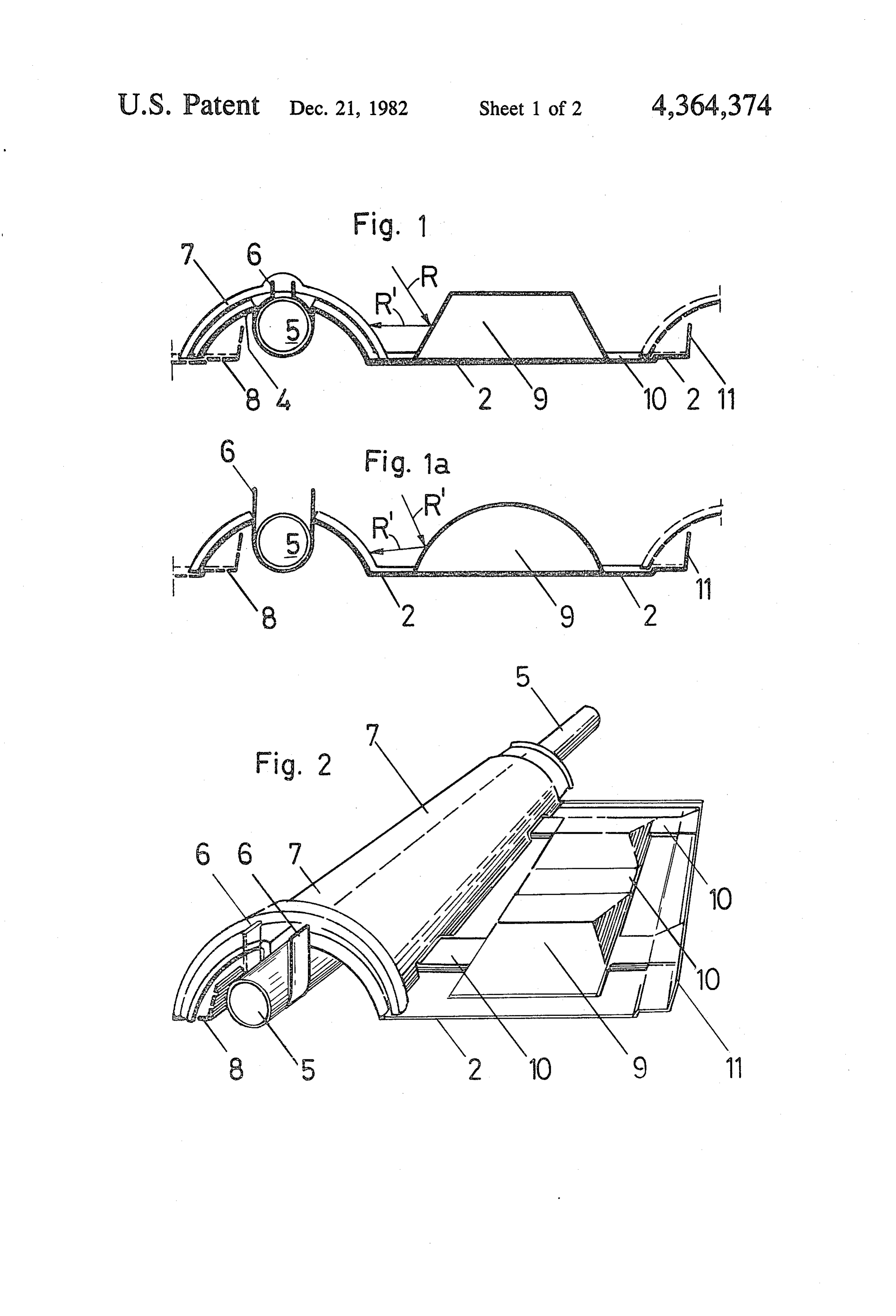
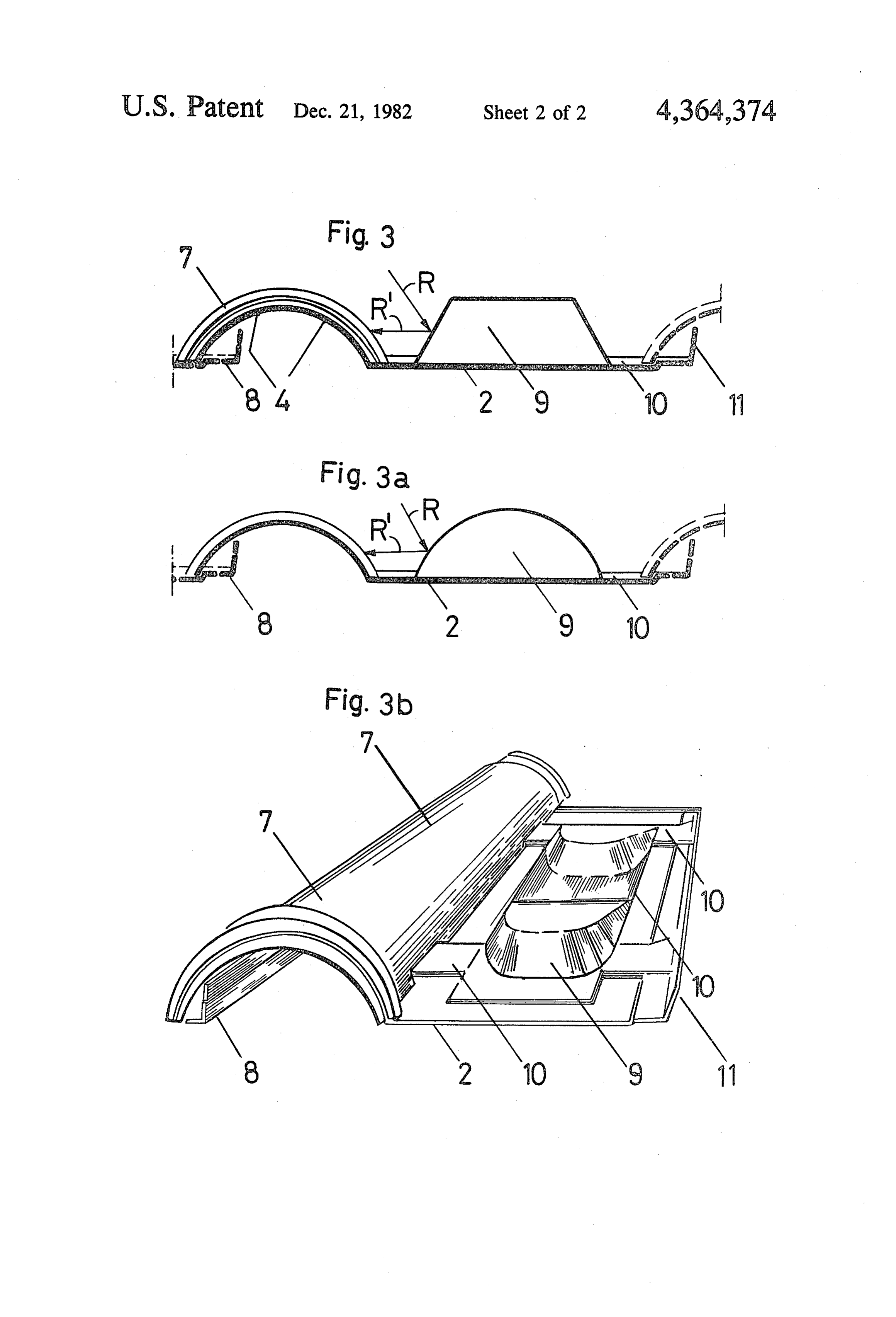
slightly differing variants of a first embodiment in metal Also, the number of throats can be increased, espe of a panel according to the invention; and cially in the case of a panel with a large surface. FIGS. 3, 3a and 3b show three slightly differing vari To avoid reflections, the external surface of the trans ations of a second embodiment. 45 parent cap, which can be of a synthetic resin, is rough FIG. 1 shows a transverse section of the panel: the ened and/or irregular while the outer surfaces of the tile 2 provides raised heat-collecting portion 4. protuberances may be so configured as to reflect the In raised portion 4 is inserted tube 5 retained by clip sunrays toward the tube as shown by the arrows R, R' spring 6 secured to the panel. Transparent cap 7 en in FIGS. 1, 1a, 3 and 3a.
closes from above the elevated portion and overlies at 50 Modifications are possible as follows: one end the following cap (not shown). The next tile 8 (a) Protuberances 9 may be formed truncated coni is shown in broken line. At 9, there is shown a pyrami cally or as spherical caps or in such a way as to present dal protuberance while at 10 are shown air conduits portions of their external surface perpendicular to the interconnecting 4 and 9. sunrays and to serve as supports for maintenance or in FIG. 2 shows a slightly modified panel in perspec 55 such a manner as to reflect sunrays toward tube 5. tive. The numbering of the same parts is identical to that (b) The tile may have two or more tubes for fluid to of the preceding figure. There is shown at 11 the lateral be heated, with corresponding transparent caps 7. edge overlain in its turn by the next tile (not shown). (c) Along its edges the tile may have channels and FIG. 3 shows another embodiment of the invention, flanges 8, 11 which permit removing it by displacing it without throat 3 and without tube 5 but with raised 60 lengthwise of the plane of the slope without having to portion 4 and transparent cap 7. The protuberances 9 move the adjacent tiles.
are preferably of pyramidal form, or in the form of (d) The tile can be applied to a panel of insulating spherical caps (FIG. 3a) or are partially truncated coni material and nailed on the surface of the roof lining by cal (FIG. 3b). The hot air below protuberances 9 is means of nails which pass through suitable eyeholes in carried by conduits 10 to raised heat-collecting portion 65 the tile and the insulating panel. 4 and thence to an air-liquid heat pump (not shown). (e) Raised portion 4 can be upwardly open so that the The portion of the panel referred to as a tile is compa tube 5 is seated and retained in the panel while being rable to a conventional ceramic tile while having protu visible from above, said tube being blackened, and fins 5 or protuberances of the panel serving to retain the tube ing a blackened base disposed upwardly so as to receive 5. solar radiation on a large surface. The cross section of (f) Raised portion 4 can be downwardly open such the tube 5 can in fact be anything desired, even having that the tile is applied onto the tube 5 and the latter is the cross section of a mushroom with a large head ex invisible from above. 5 posed to solar radiation.
(g) The tile can have cavities disposed in its surface (o) The pyramidal, truncated conical, spherical cap turned toward the sun and can have a concave, spheri shaped or other Without departing from the scope of cally capped, pyramidal or truncated conical shape. the appended claims as those skilled in this art will (h) Each tube 5 can be fixed in the tile by a cement or readily understand.
substance having good thermal conductivity. O What is claimed is:
(i) The panel can be partially or completely com 1. Solar energy absorptive panel for covering roofs, posed of several materials disposed in layers, the exter comprising a tile (2) having at least one downwardly nal layer being transparent. opening raised portion (4) which collects heat, a trans (j) Elemental panels can be interconnected and dis parent cap (7) that covers, insulates and protects the posed as conventional tiles with the same aesthetic ef raised portion, the tile having at least one protuberance fect so that the raised portions for the tubes will be (9) defining a downwardly-opening cavity, said protu continuous from the bottom to the summit of the incline berances and raised portion being interconnected of the roof, thereby to permit insertion of tubes inter least one conduit (10) permitting circulation of the by at connected endwise in conventional collector tubes and air to integrate all the surface of the roof into the solar contained in said protuberance so as to transport heat energy collecting equipment. toward said raised collector portion (4), said protuber (k) Panels which are associated and form the cover ance (9) being so shaped as to reflect the sunrays toward ing can be slightly elevated above the support surface, the raised collector portion.
each elemental panel having, toward its base, projecting 2. Panel according to claim 1, and at least one up portions which serve to space the panels from the sup 25 wardly opening spring clip (6) in said raised portion (4), port and which serve to facilitate heat exchange be and a metallic tube (5) seated in said spring clip and tween the tile and the fluid circulating beneath it. through which flows the fluid to be heated. (1) In the space between the assembly of panels and 3. Panel according to claim 1, in which the protuber the support surface can circulate air whose heat is recu ances (9) have the form of pyramids, truncated cones, or perated as by an ordinary air-liquid heat pump. 30 spherical caps so as to present portions of their external (m) Several panels can be interconnected in such a surface perpendicular to the sunrays and to serve as way as to form a unit facilitating emplacement of the support for the feet of workers during maintenance. assembly. 4. Panel according to claim 1, in which the external (n) The transverse section of the tube 5, instead of surface of the transparent cap is roughened and/or being circular, can be polygonal, square, rectangular, 35 irregular so as to prevent reflection. trapezoidal, semi-circular or triangular, each tube hav k s k
Provenance
- Collection
- Patents citing this work
- Pages
- 5
- Method
- pdftotext (the PDF's own text layer) + pdftoppm 300dpi page scans
- Patent office record
- patents.google.com →
- Source
- Google Patents citing-documents table
- Assignee
- Elioform Ag
- Published
- 1982-12-21
- Transcribed from
- patentimages.storage.googleapis.com →