

patent · US4372291A
Solar heat exchanger
8 February 1983
Text
Page 1bibliographic recordscan →
United States Patent (19)
Schwartz
54). SOLAR HEAT EXCHANGER
(76) Inventor: David M. Schwartz, Washington,
(51) Int. Cl. ................................................. F24 3/02 (52) U.S. C. .................................... 126/443; 126/417; e 126/438; 126/442
4, 124,020 1 1/1978 Noble ... ... 126/901 X 4,136,670 1/1979 Davis .................................. 26/440 4, 153,042 5/1979 Tragert .. ... 126/901 X 4, 186,724 2/1980 Nelson ...... ...... 26/443 4,237,868 12/1980 Overton .............................. 126/443
e - un was www.wrw as u was a wasnuwa w w a raw as w uwasaki wa war aww.
Primary Examiner-Larry Jones
A Solar heat exchanger for vaporizing virtually all the liquid entering the exchanger. The solar heat exchanger Of the invention is comprised of a metal tube, a feedwa ter inlet tube of much smaller diameter located within the metal tube and a transparent glass envelope enclos ing the metal tube. The annular space between the inner surface of the glass envelope and the outer surface of the metal tube is evacuated to pressure of 10-6 torr. A vapor outlet pipe is provided at one end of the ex changer. A feedwater inlet pipe extends from the oppo site end of the exchanger within and for approximately the length of the interior of the metal tube. In use in coming feedwater is pumped through the feedwater pipe and sprays outwardly through small spray orifices onto the hot inside surface of the metal tube, which converts it to steam.
16 Claims, 7 Drawing Figures
Drawings
Page 2drawing sheetscan →
Page 3drawing sheetscan →
Page 4drawing sheetscan →
Page 5scan →
smaller opening is provided at the opposite end of the
SOLAR HEAT EXCHANGER metal tube for insertion of a feedwater inlet pipe. The feedwater inlet pipe is located near the inner side wall
BACKGROUND OF THE INVENTION surface of the metal tube and opposite the steam outlet 1. Field of the Invention pipe. The feedwater inlet pipe extends into the interior The present invention relates to a solar type heat space length of the metal tube traversing approximately the of the interior space of the metal tube.
exchanger for converting incoming liquid to hot vapor. The feedwater inlet pipe is provided with small water 2. Description of the Prior Art spray holes along the length of the feedwater pipe. The In conventional prior art solar heat exchangers, a 10 small orifices are spaced uniformly along the pipe sur feed liquid entering the exchanger is normally either face and are in close proximity to each other. Each heated by sunlight energy to produce a non-boiling orifice hole runs completely through the side wall sur liquid at higher temperature or a percentage of the entering liquid is vaporized and the remainder accumu face providing a fluid outlet means therethrough from the interior of the feedwater pipe. As water is pumped lates and passes from the exchanger as a liquid. In the 15 through the feedwater pipe, the water passes through first type of solar heat exchanger commonly referred to as an indirect solar exchanger, the non-boiling liquid the spray orifices. The pressure of the water causes the must be passed to a second (non-solar) conventional water to spray out from the orifices and impact against heat exchanger in which heat energy is transferred the hot inside surface of the metal tube whereupon the indirectly from the hot non-boiling liquid to another 20 water is completely vaporized before it reaches the liquid such as water to vaporize the second liquid, so as bottom of the chamber. Thus, better heat transfer to the to produce steam or other useful vapor. The disadvan liquid is obtained by spraying the liquid against the hot tage of this particular conventional type of system is inside surface of the metal tube than would otherwise that additional (non-solar) type indirect heat exchangers occur if the liquid was simply passed into the tube inte are required, thus adding to the cost and complexity of 25 rior space designated as the steam chamber. The wet the sytem. On the other hand solar heat exchangers of ting action of the inside metal tube surface by the spray the second type commonly referred to as insitu type means of the present invention permits virtually all the exchangers disclosed in the prior art normally have a incoming water to be converted to steam so that essen disadvantage of bulky design and lower heat transfer tially no liquid water pool accumulates within the ex rate per unit tube surface area generally attributable to changer. A sensing means within the metal tube interior the greatly enlarged steam chamber required to accom 30 space, i.e. within the steam chamber, is provided to modate the boiling liquid and steam produced within regulate the flow of incoming water.
the exchanger. Another disadvantage of this latter type The present invention therefore provides an effective of solar heat exchanger is that in view of the reduced means for impacting the incoming feed liquid against heat transfer rate only a portion of the incoming liquid 35 the inside heat transfer surface of the steam chamber is converted to vapor within the exchanger. The uncon wetting the surface with a thin film thereby increasing verted portion accumulates to form a liquid pool within the rate of heat transfer to the liquid. This feature cou the exchanger and excess liquid must be removed.
The present invention overcomes these disadvan pled with the location of the feedwater inlet tube in relation to the steam outlet pipe and size of the steam tages of the prior art solar heat exchangers by providing chamber compact means for increasing the rate of heat transfer to enhancedinsteam relation to the feedwater inlet pipe produces production per unit heat transfer sur the liquid passed into the exchanger so that virtually all face area and permits incoming liquid is converted to steam or useful vapor liquid to be convertedvirtually all the incoming feed within the solar exchanger itself without need for addi residual liquid pool to accumulatewithout to vapor within allowing a the steam tional (non-solar) heat exchangers. 45 chamber.
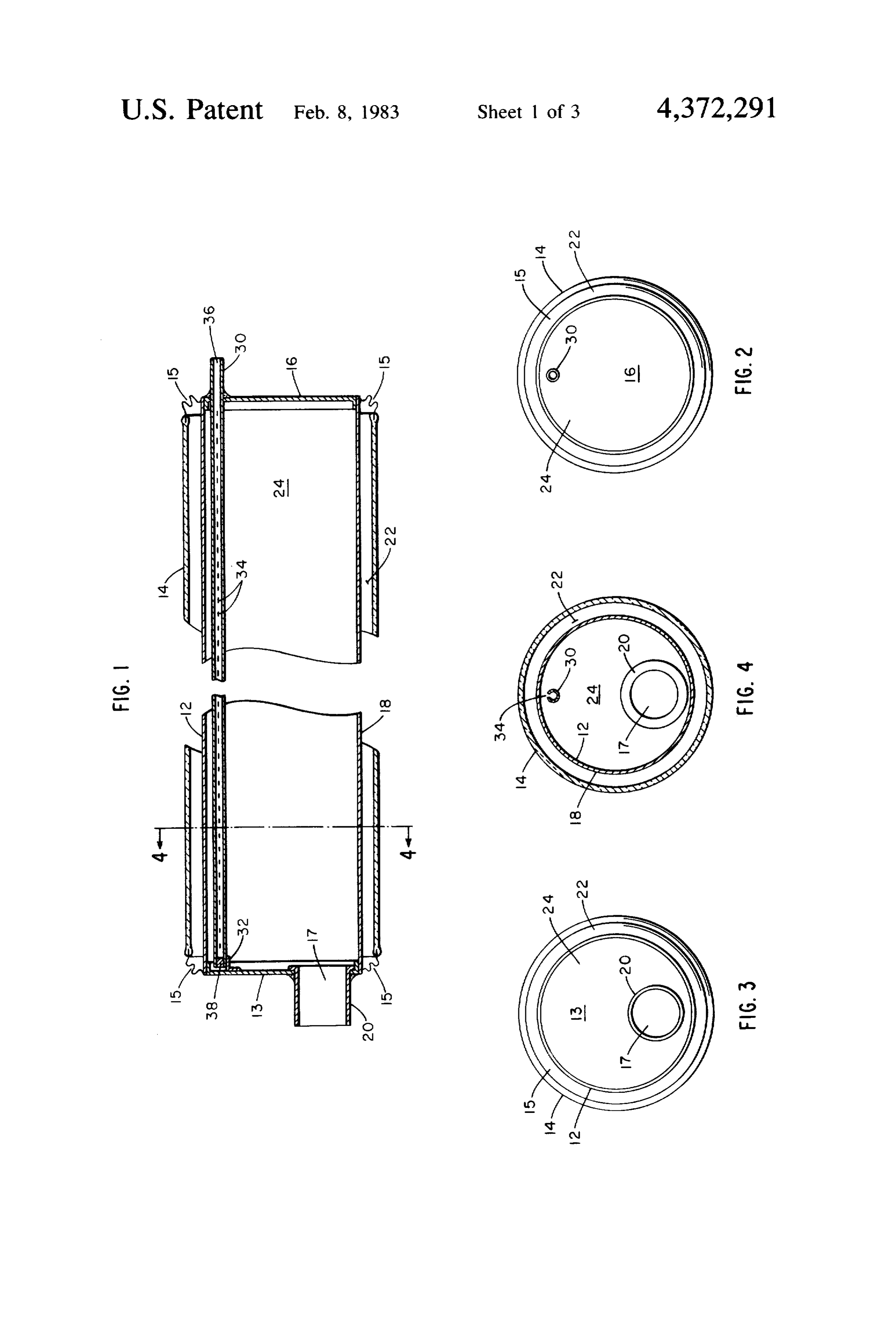
SUMMARY OF THE INVENTION BRIEF DESCRIPTION OF THE DRAWINGS It is a principal object of the present invention to FIG. 1 is a sectional elevation view of a solar heat provide a compact solar heat exchanger for vaporizing exchanger embodying the invention. a liquid by utilizing sunlight energy without resort to FIG. 2 is an end view looking from the right of FIG. external heat sources. 50
It is also an object of the invention to provide a solar FIG. 3 is an end view looking from the left of FIG. 1. heat exchanger of compact design for converting water to steam within the solar exchanger itself without resort 4-4 of 4FIG.
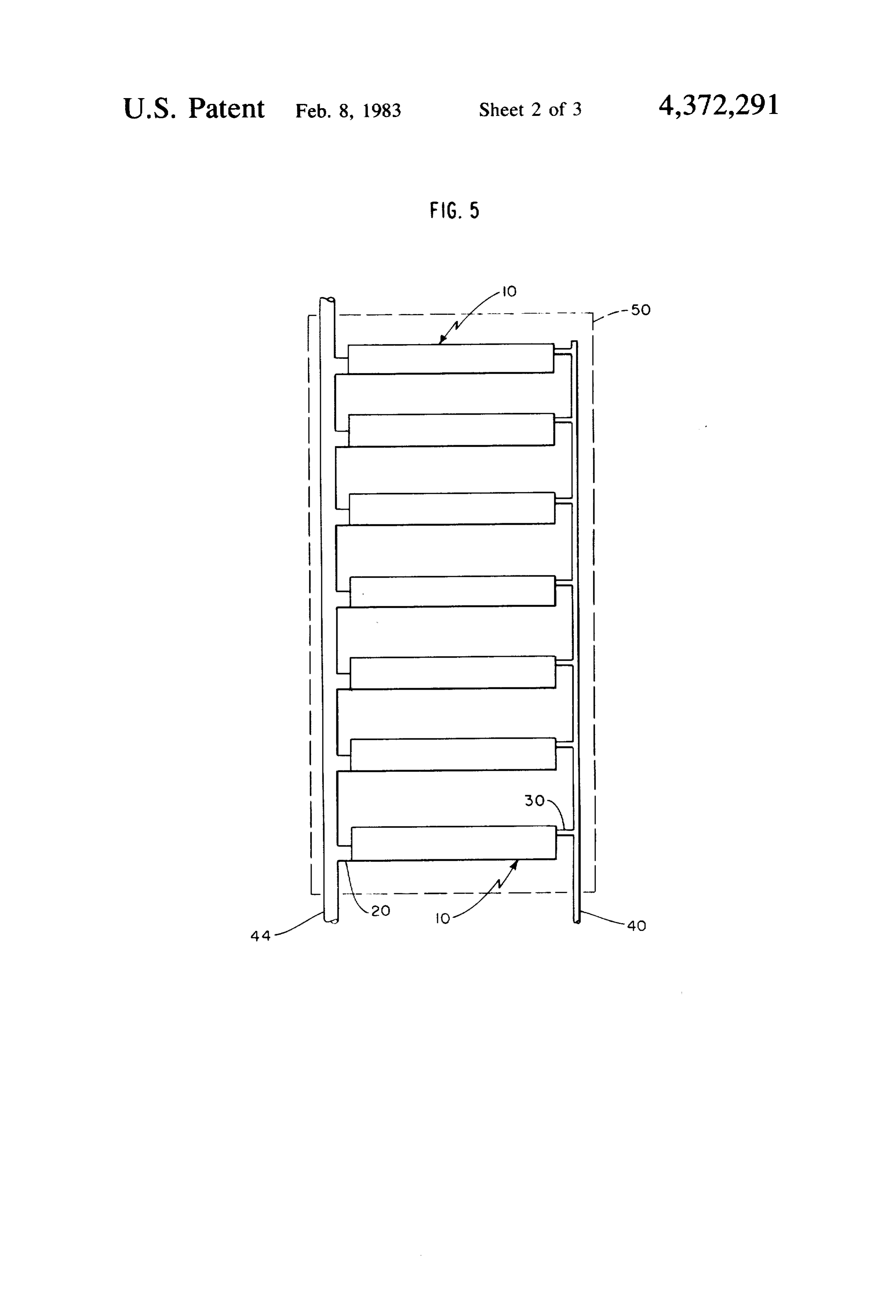
FIG. is a sectional side view taken along the line to additional heat exchangers or other heat transfer 55 FIG. 5 is a plan view of one panel comprising a plu eaS rality
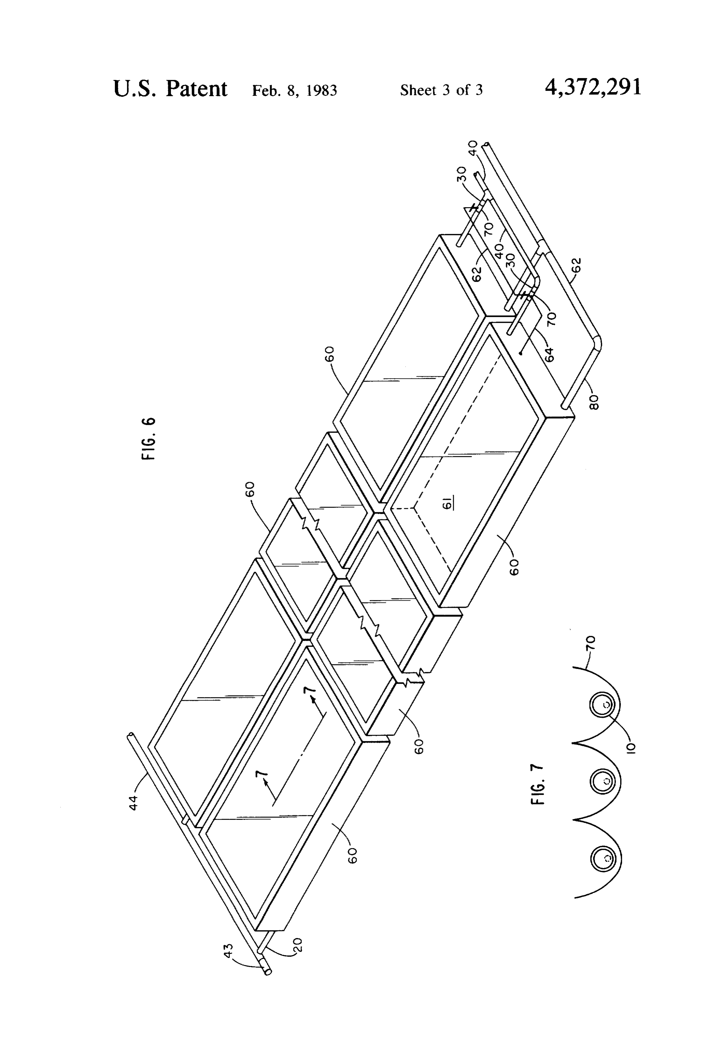
It is an object of the invention to provide a solar heat tion. of individual solar heat exchangers of the inven exchanger which converts virtually all incoming water FIG. 6 is an isometric view of an array comprised of to steam without accumulation of a liquid pool within a plurality of panels.
the exchanger. FIG. 7 is a sectional view taken along the line 7-7 of The solar heat exchanger of the invention is com FIG. 6.
prised of a metal tube, a feedwater inlet tube of much smaller diameter located within the metal tube and a DESCRIPTION OF THE PREFERRED transparent glass envelope enclosing the metal tube. EMBODIMENTS The metal tube is closed at each end. An opening is 65 A preferred embodiment of the solar heat exchanger provided at one end of the metal tube for affixing a steam outlet pipe in communication with the interior of of the invention is illustrated in FIG. 1. The steam solar exchanger 10 is comprised of a metal boiler tube 12, a the metal tube. The steam outlet pipe is located approxi feedwater inlet tube 30 of much smaller diameter lo mately tangential to the side surface of the metal tube. A 6 cated within the metal tube and a transparent glass Bellows 15 are sealed to metal tube 12 by a conventional envelope 14 enclosing the metal tube 12. The metal tube glass to metal iron sealing alloy such as "Kovar' or "52 is constructed preferably of stainless steel coated with a Alloy'. The inner and outer peripheries of the bellows suitable heat absorbtion coating such as black tungsten are longitudinally displaced from one another to better or black chrome on nickel. The metal boiler tube 12 is accommodate both differential radial and linear expan comprised of cylindrical side surface 18, a closed front sion of the metal and glass tubes. Preferably the outer metal end cap 13 and a closed rear metal end cap 16. periphery of the bellow is sealed in a glass to metal seal The interior of tube 12 bounded by end caps 13 and 16 to the glass tube 14 and the inner periphery of the bel and side wall surface 18 defines a steam chamber 24, low is sealed to the metal tube 12 as disclosed in the The front metal end cap 13 is provided with an opening O above cited U.S. Pat. application, Ser. No. 891,210 filed 17 located nearly tangential to the end cap circumfer 3/29/78.
ence as best illustrated in FIG. 3. A steam outlet pipe 20 In application sunlight heat energy passes through is placed within opening 17 and welded to end cap 13 so the transparent glass tube and is absorbed by the coated that one end of the steam outlet pipe rests approxi metal tube surface 18 thereby raising the temperature of mately flush against the inside surface of end cap 13 as 15 the tube surface to about 600 F. without the use of illustrated in FIG. 1. The end cap 16 is provided with a mirrors or light concentrators. The vacuum annular small opening 31 near the circumferential edge of cap space 22 prevents convective heat from escaping from 16, nearly tangential to the metal tube side wall surface the metal tube surface and the selective coating on the 18. The openings 17 and 31 are preferably displaced as metal surface minimizes heat loss by infrared radiation. far as possible from each other as best illustrated in FIG. If light concentrating means such as mirrors or lenses 4. are employed in addition to the evacuated annular The feedwater tube 30 is comprised of a straight pipe space, the temperature of the metal tube surface 18 may preferably of type 304 stainless steel construction hav reach to about 1200F. As water at about 50 to 1500 psia ing an open end 36 and a closed end 38. The feedwater pressure or other suitable fluid is pumped through feed tube 30 is provided with small holes or spray orifices 34 25 water tube 30, the fluid passes through the spray orifices along the length of the tube. The small orifices approxi 34. Water emanating from spray orifices 34 impacts mately 0.005 inches to 0.050 inches in diameter are against the inside metal wall surface of metal tube 12 spaced uniformly along the tube surface about 0.1250 whereupon it is converted to saturated steam. The inches to 0.250 inches apart in close proximity to each steam passes from the interior chamber 24 through other. Each small spray orifice may be made by simple 30 steam outlet pipe 20 and may be utilized in any service drilling, saw cutting or laser burning of small holes requiring low pressure steam approximately in a range through the tube 30 surface. between 20 to 200 psia.
Each orifice hole runs completely through the wall A conventional immersion sensing device (not surface providing a fluid outlet means therethrough shown) within the chamber regulates the flow of feed from the interior of tube 30. The tube 30 may be located 35 water through inlet tube 30 by controlling a variable within the metal boiler tube 12 by inserting the closed feedwater valve. Virtually all the feedwater, i.e., at least end 38 of tube 30 through opening 31 and aligning tube 99.0% of the feedwater entering tube 30 and chamber 30 approximately parallel to tube side surface 18. A 24 is converted to steam in chamber 24. Thus, virtually bracket 32 affixed to the inner surface of end cap 13 is no liquid pool accumulates within chamber 24. The provided to secure the closed end 38 of the feedwater increased wetting effect of water sprayed under pres tube. Bracket 32 is aligned with opening 31 and placed sure through orifices 34 and impacting against the hot sufficiently away from the circumferential edge of the inside metal tube wall surface 18 coupled with the elon end cap 14 so that the feedwater tube rests approxi gated design of chamber 24 in relation to inlet tube 30 mately parallel to the metal tube side wall surface 18. permits increased heat transfer to occur than in conven The feedwater tube surface is no closer than about 0.060 45 tional solar collector designs and virtually all of the inches to the metal tube side wall surface 18. The open incoming feed liquid is converted to vapor. The disad end 36 of the feedwater tube extends at least 0.50 inches vantage in conventional solar heat exchangers which through opening 31. The feedwater tube 30 may be permit a residual liquid pool to accumulate within the welded to the peripheral edge of opening 31 to provide chamber 24 is prevented. In view of the increased heat a permanent water tight seal securing the tube 30 to end 50 transfer obtained by employing the design of the present cap 16. The preferred location of the feedwater tube 30 invention a higher liquid to vapor conversion rate is relative to the circumferential edge of end cap 16 is best obtained than in conventional solar heat exchangers for illustrated in FIG. 2. the same metal surface area 18 available for heat trans The glass envelope 14 encloses metal tube 12. The fer.
envelope 14 is preferably a transparent glass tube hav 55 A plurality of solar heat exchangers 10 may be ar ing an inside diameter about 0.250 to 0.80 inches larger ranged in parallel to form one solar collector panel. A than the outside diameter of metal tube 12 so that an typical solar panel comprised of seven solar heat ex annulus 22 of about 0.250 inches in width is formed changers 10 of the present invention is illustrated in around the metal tube. The annulus is defined by the FIG. 5. The solar exchangers depicted in FIG. 5 have metal tube outer surface and the glass envelope inner the inlet feedwater tube 30 connected to a common surface. The annulus space 22 is illustrated in FIGS. 1 feedwater inlet manifold 40 and similarly the steam through 3. The annulus space 22 is evacuated to a pres outlet pipe 20 emanating from each solar exchanger is sure of about 10-6 torr. Bellow seals 15 preferably of connected to a common steam outlet manifold 44. Such the type and construction disclosed in allowed U.S. Pat. design reduces the amount of piping needed both to application, Ser. No. 891,210 filed 3/29/78 are provided 65 carry water to the solar exchangers and to carry prod along the circumferential edge of each end of the glass uct steam from them. Also compacting a plurality of tube 14. The bellows 15 are of metal construction pref. heat exchangers in a common space provides for better erably of ASTM 103 phosphor bronze or stainless steel. utilization of finite volume of space available and ex 7 posed to sunlight. A container 60 having a transparent ence (AT) in a range of about 50 F. to almost 400' F. cover 61 preferably of tempered low-iron glass trans between the tube metal 12 surface temperature and the parent material is provided to house each panel 50 com above saturated steam temperature. For example, with the prising a plurality of solar exchangers 10. The contain stated size dimensions and a tube metal 12 surface ers 10 each having a plurality (panel) of solar exchang temperature of about 600 F., about 0.05 ounces wt. per ers therein may be arranged in side by side pattern de minute of water at 50 psia (sat. temp. 281". F.) may be picted in FIG. 6 to form an array of solar exchangers. converted to saturated steam with virtually no residual The panel of solar heat exchangers preferably employ liquid pool accumulating within steam chamber 24. 2X magnification non-imaging concentrating mirrors An example of the operation of the preferred embodi positioned at the base of each container 60 and partially 10 ment of the invention wherein the individual solar ex circumventing each solar heat exchanger within the changers are arranged in panels (FIG. 5) and the panels panel as best illustrated in FIG. 7. The use of non-imag grouped to form an array (FIG. 6) is given as follows: ing concentrating mirrors permits the tube metal sur An array comprised of 77 panels, with each panel face 18 to reach a temperature as high as 1200' F. under comprising 7 solar heat exchangers of the present inven average sunlight conditions of 275 BTU/ft2. 15 tion coupled to 2.0X non-imaging mirrors is arranged as The array of exchangers may be provided with com illustrated in FIGS. 5 and 6. Thus, the array is com mon feedwater inlet manifold 30 and common steam prised of 539 solar heat exchangers. The array of panels outlet manifold 44 as illustrated in FIG. 6. An inlet cover a surface area 57 feet in length and 44 feet 2 feedwater tube 30 connected to common manifold 40 inches in width. The exposed surface area 61 of each may be arranged to supply the plurality of solar heat 20 panel to sunlight is approximately 26 square feet. There exchangers within each panel. Each feedwater inlet fore, the total exposed surface area of the entire array of manifold 30 is provided with a valve 70 and immersion panels is about 2,000 feet. Each solar heat exchanger sensing wire 64 connected to one solar exchanger cham conforms to the foregoing preferred embodiment de ber 24 per panel. The sensing wire 64 and valve 70 are scription. Each solar heat exchanger is comprised of a thus adapted to control the rate of water to each panel. 25 stainless steel metal tube 12 having a length of about 48 Any small amount of condensate which may be present inches and inside diameter of about 1 inches encased in within steam outlet pipe 20 may be removed from the a transparent glass tube 14 having an inside diameter of system by condensate return line 80 connected to each about 2 inches and a feedwater inlet pipe of about steam outlet pipe. inch inside diameter and a steam outlet pipe of inch Although the size dimensions for each solar heat 30 inside diameter. The feedwater pipe is constructed of exchanger, e.g., metal tube surface area available for type 304 stainless steel and has a 0.015 inch wall thick heat transfer, steam chamber size and flow rate of in ness. The metal tube 12 and glass tube 14 are sealed by coming water may vary somewhat and yet be within bellows 15. If concentrator mirrors of 2.0X magnifica the scope of the present invention the following specifi tion are used, then under average sunlight conditions of cations have been found to permit particularly favor 35 275 BTU/FT2, a tube metal 12 surface operating tem able results: It has been determined that a particularly perature of about 1200' F. can be reached in each solar suitable design results when the solar exchanger of the exchanger. Water (or other suitable heat transfer liquid) invention is comprised of a metal tube 12 having an is pumped into the feedwater inlet pipe at about 50 psia inside diameter of about 1 inches encased in a transpar pressure and at about 90 F. at a rate of about 0.345 lbs/hr. per exchanger. Virtually all, i.e., greater than ent glass tube having an inside diameter of about 2:
inches, a feedwater inlet pipe about inch inside diame 99% of the incoming water, is converted to steam ter and a steam outlet pipe of about inch inside diame within the interior of the metal tube 12, i.e., within the ter. The feedwater pipe is preferably constructed of chamber 24 of each solar exchanger. Thus, the array of the present example occupying a type 304 stainless steel of 0.015 inches wall thickness. A suitable design length for the metal tube 12 having the 45 total area of about 2500 feet? and comprising 539 solar aforementioned size dimensions may be about 48 inches, heat exchanger tubes converts approximately 186 The metal tube 12 is preferably constructed of type 304 lbs/hr. of water at 50 psia pressure to saturated steam at about 50 psia (sat. temp. 281 F.) without the use of any stainless steel having a wall thickness of 0.040 inches. other heat source other than average sunlight condi Thus, the ratio of steam chamber 24 volume to metal surface area 18 of this preferred design is in a ratio of 50 tions of 275 BTU/FT2. The steam may then be used for one-fourth the metal tube diameter or 0.44 in/in2. It has heating purposes or industrial use, for example, in the been found that a solar heat exchanger of design illus other process of canning vegetable or in making paper or trated in FIGS. 1-4 as described in the preferred em temperature uses where steam at the above-described rate, bodiment and having the above-stated size dimensions 55 Although and pressure is desirable. permits a metal surface temperature of about 600' F. to with referencethetopresent invention has been described use of water as the heat transfer me be reached without employing mirrors or light concen dium it should be understood that a variety of other heat trators and will permit conversion of about 0.173 transfer medium such as Fluorocarbons or ammonia lbs/hrs. of water at 50 psia to saturated steam. If light may be used instead.
concentrators or mirrors are used with a magnification 60 Also, although the present invention has been de factor of 2,0X the metal surface 18 can reach a tempera ture as high as 1200' F. permitting conversion of 0.345 scribed with reference to a preferred embodiment it lbs/hr. of 50 psia water to saturated steam for a solar sibleshould be appreciated that variations of design are pos heat exchanger of the invention having the above-stated Therefore, without departing from scope of the invention. dimensions. Without the use of mirrors or other concen it is not intended that the invention be lim trators it has been determined that under average sun 65 ited to the preferred embodiment described. Rather the light conditions of 275 BTU/FT, the present preferred scope of the invention to be determined by the scope of embodiment having the above-stated dimensions may theWhat claims and equivalents thereof. is claimed is:
operate satisfactorily with a range in temperature differ
Page 8scan →
1. A solar heat exchanger for vaporizing within the 4. A solar heat exchanger as in claim 1 wherein the exchanger virtually all feed liquid heat transfer medium vapor outlet opening is located nearly tangential to the which enters the exchanger by utilizing solar light en inside wall surface of the metal boiler tube. ergy as the heating source, said solar heat exchanger 5. A solar heat exchanger as in claim 4 wherein the comprising: vapor outlet opening has a diameter of about inches a closed metal boiler tube wherein vaporization of and the heat exchanger includes an outlet pipe of ap feed liquid entering the exchanger occurs, said proximately the same diameter as the outlet opening metal tube coated with heat absorbent coating and affixed to the circumferential edge defining said vapor having an inlet opening for admitting the feed liq O outlet opening.
uid into the metal boiler tube and an outlet opening 6. A solar heat exchanger as in claim 1 wherein the for passing the vaporized product from the metal metal boiler tube has an inside diameter of approxi mately 1 inches and the transparent glass tube has an boiler tube, a transparent glass tube enclosing the metal tube and inside 7. A diameter of about 2 inches.
solar heat exchanger as in claim 1 wherein the forming an annular space between the glass tube 15 length of the metal boiler is approximately 48 inches. and the metal boiler tube, said annular space evacu 8. A solar heat exchanger as in claim 7 wherein the ated to vacuum pressure, and wall thickness of the metal boiler tube is about 0.050 a spray tube of small diameter relative to the diameter inches.
of the metal boiler tube, said spray tube located 9. A solar heat exchanger as in claim 1 wherein the within the metal boiler tube and having a plurality metal boiler tube and the spray tube are constructed of of spray orfices in close proximity to each other stainless steel.
placed along the length of the spray tube, one end 10. A solar heat exchanger as in claim 1 wherein the of said spray tube being in communication with metal boiler tube is constructed of copper. said inlet opening of said metal boiler tube, said feed liquid entering said exchanger at a pressure 25 liquid feed enteringexchanger 11. A solar heat as in claim 1 wherein the the exchanger is subcooled water at sufficient to produce a continuous spray of said a pressure of about 50 psia and the vapor product is feed liquid through the spray orifices of said spray tube, said spray continuously impacting against the saturated steam at about 50 psia pressure. 12. A solar heat exchanger as in claim 1 wherein the inside surface of said metal boiler tube to improve water entering the heat exchanger is at a pressure of the rate of heat transfer to the feed liquid so that 30 about 50 psia and a temperature of about 70 to 220 F. virtually all the liquid entering the metal boiler 13. A solar heat exchanger as in claim 1 wherein the tube is converted to vapor within said metal boiler metal boiler tube outer surface is coated with black tube. chrome on nickel, 2. A solar heat exchanger as in claim 1 wherein the 14. A solar heat exchanger as in claim 1 including spray tube is open at the inlet end and closed at the 35 non-imaging concentrating mirrors at least partially opposite end, has a length approximately equal to the circumventing the transparent glass tube. length of the metal boiler tube and is located in close 15. A solar heat exchanger as in claim 14 operating at proxmity to the inside wall surface of the metal boiler a metal boiler tube surface temperature of about 1200 tube. F. under average sunlight conditions. 3. A solar heat exchanger as in claim 2 wherein the 16. A solar heat exchanger as in claim 1 operating at spray tube is approximately inch in diameter and the a metal boiler tube surface temperature of about 600 F. spray orifices therein are approximately 0.0125 inches in under average sunlight conditions. diameter and spaced about 0.20 inches apart.
Provenance
- Collection
- Patents citing this work
- Pages
- 8
- Method
- pdftotext (the PDF's own text layer) + pdftoppm 300dpi page scans
- Patent office record
- patents.google.com →
- Source
- Google Patents citing-documents table
- Assignee
- Schwartz David M
- Published
- 1983-02-08
- Transcribed from
- patentimages.storage.googleapis.com →