

patent · US4383891A
Device for desalting brackish water, and a conditioning method and device relating to said desalting device
17 May 1983
Text
Page 1bibliographic recordscan →
United States Patent (19)
Clavier
(54) DEVICE FOR DESALTNG BRACKSH
WATER, AND A CONDITIONING METHOD
AND DEVICE RELATING TO SAD
DESALTING DEVICE
75 Inventor: Philippe Clavier, Marly Le Roi,
France Assignee: Spie-Batignolles, Puteau, France
Related U.S. Application Data 63 Continuation-in-part of Ser. No. 70,498, Aug. 28, 1979,
51 Int. Cl. ............................................... B01D 3/02 U.S. Cl. ...................................... 202/234; 159/15;
2,803,591 8/1957 Coanda et al. ........................ 159/15
4,141,798 2/1979 Grosse ................................. 202/234
FOREIGN PATENT DOCUMENTS
Primary Examiner-Frank Sever
Attorney, Agent, or Firm-Fleit, Jacobson & Cohn
A device for desalting sea or brackish water by means of solar energy essentially comprises two adjacent ca nals or equivalent systems fed with seawater or brackish water and a greenhouse-type structure placed over one of the canals for evaporating the water. A fresh-water condensing and collecting structure is adapted to com municate with the greenhouse structure and is largely immersed in the water of the other canal which per forms the function of a cold source for the condensing Structure. - 1.
12 Claims, 21 Drawing Figures
Drawings

Page 2drawing sheetscan →
Page 3drawing sheetscan →
Page 4drawing sheetscan →
Page 5drawing sheetscan →
Page 6drawing sheetscan →
Page 7drawing sheetscan →
Page 8drawing sheetscan →
Page 9drawing sheetscan →
Page 10scan →
establishing a communication between each canal and
DEVICE FOR DESALTING BRACKISH WATER, the aforementioned feeder canal. AND A CONDITIONING METHOD AND DEVICE It is already a known fact that seawater contains RELATING TO SAID DESALTING DEVICE approximately 4.5% by weight of salt (density 1.03) but could contain up to 26 % before being saturated. It is
This application is a continuation-in-part of my appli thus possible to obtain fresh water by evaporation of cation Ser. No. 070,498 filed on Aug. 28th, 1979, now seawater without any attendant formation of salt depos U.S. Pat. No. 4,292,136. its as long as the seawater employed is renewed before The invention relates to a device for desalting seawa its salinity exceeds the critical value. It must neverthe ter or brackish water using solar energy, as well as to a 10 less be ensured that the temperature maintained within method and a device for conditioning the atmosphere of the evaporation canal is sufficient to obtain a useful a greenhouse in conjunction with said desalting device. partial vapor pressure. By reason of the fact that the It is known to evaporate brackish water by employ available solar energy is limited, the quantity of sea or ing solar radiation with a view to obtaining fresh water, brackish water to be processed must not exceed require especially for irrigation purposes. To this end, masses of 15 ments. It is for this reason that periodic trapping and water are exposed to sunshine with or without an opti renewing of water are necessary in order to achieve a cal focusing structure in orde to obtain evaporation. higher yield.
The vapor is retained within the enclosure and con The cold source provided by the second canal men densed on the enclosure walls. The problem of efficient tioned above is simply the consequence both of natural condensation is not satisfactorily solved. 20 evaporation of the seawater which acts as a regulator Further problems arise in the particular case in which and also of re-radiation at night.
solar energy is utilized in conjunction with brackish According to a second aspect of the invention, the water for the purpose of conditioning premises or a method for conditioning the atmosphere of an enclosed room designated hereinafter as an enclosed area, and area and especially a greenhouse utilizes solar energy especially a greenhouse. 25 and essentially consists in focusing the sun's rays on a The solar radiation admitted into the greenhouse mass of water located within the enclosed area so as to must in fact be sufficient to cause evaporation which in cause at least partial evaporation of the water and in turn produces a suitable degree of atmospheric humid passing through the enclosed area a predetermined flow ity and a quantity of condensed fresh water which is of water which is subjected to focused solar radiation in sufficient for irrigation of the soil. But the heat thus 30 order to remove from the enclosed area part of the heat introduced into the greenhouse is the cause of a temper generated within said area by the solar radition. ature rise which often proves unacceptable. Correla It is thus found possible to reconcile two objectives tively, in areas in which solar energy is utilized, the which are usually contradictory: - - greenhouse must be protected against low night temper that of obtaining the desired output of fresh water; atures. 35 that of obtaining within the enclosed area a desired . A first aim of the invention is to provide a device for temperature, which is unrelated to the aforemen desalting brackish water, especially in which reconden tioned flow of water.
sation of evaporated water is carried out both economi Preferably, the reheated water which has been re cally and efficiently and makes it possible to obtain high moved from the enclosed area is then circulated within yields of fresh water. said area during the night in order to compensate for the A further aim of the invention is to provide a method effects of low night temperatures. Provision is advanta and a device for conditioning the atmosphere of an geously made for an optical focusing structure on one enclosed area in such a manner as to secure the advan face of the enclosed area which is oriented in the direc tages mentioned in the foregoing. tion of maximum height of the sun during the daytime According to a first aspect of the invention, the de- 45 and the angle of slope of said structure is varied accord vice for desalting sea or brackish water by means of ing to the seasons of the year.
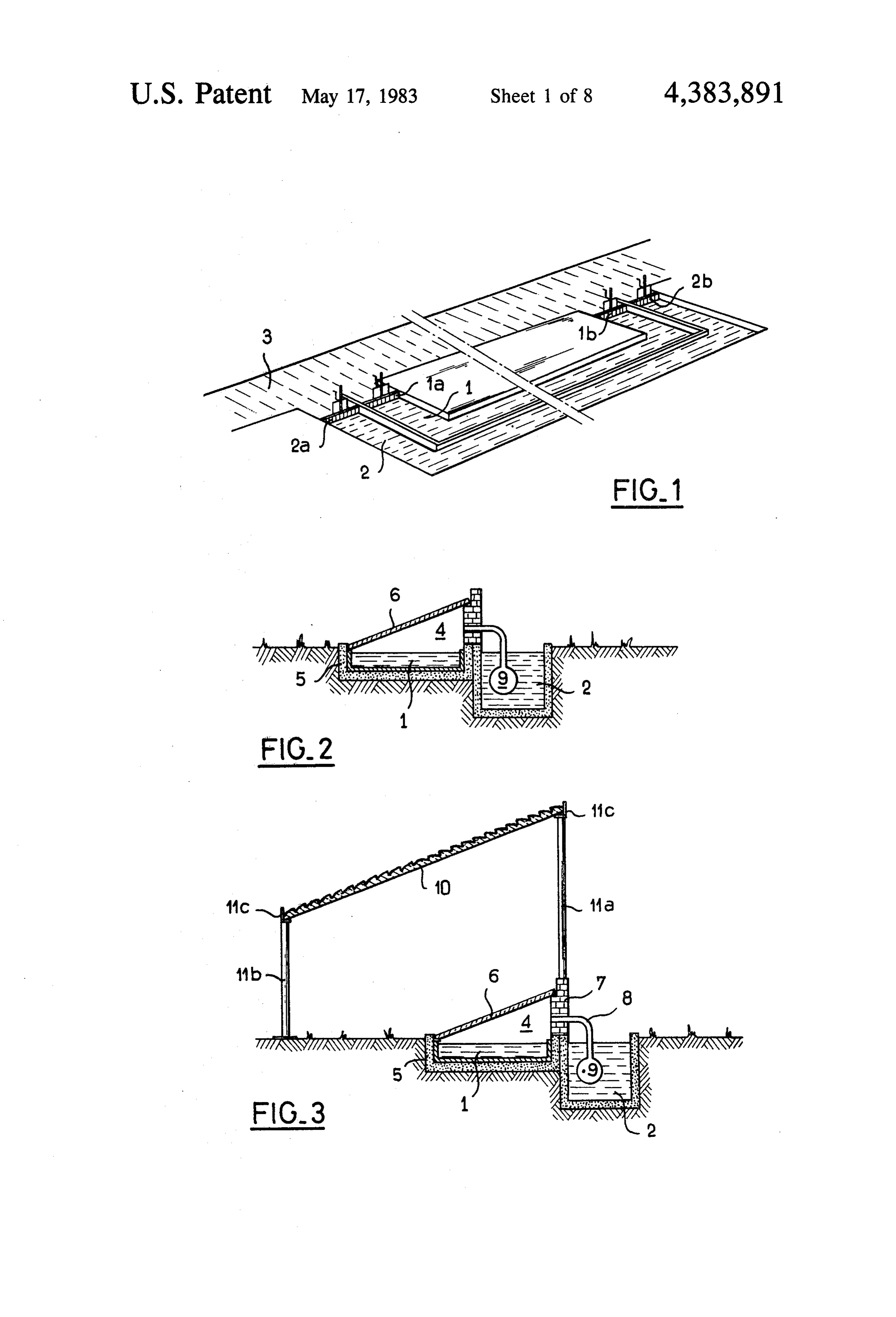
solar energy essentially comprises two adjacent canals If no allowance is made for diurnal variations of incli or equivalent systems fed with seawater or brackish nations of the sun but only for seasonal variations, the water, a greenhouse-type structure placed over one of mechanism for producing a displacement of said struc said canals for evaporating the water, and a fresh-water 50 ture is considerably simplified. condensing and collecting structure adapted to commu . . According to a third aspect of the invention, the nicate with said greenhouse structure and mainly im- . device for conditioning the atmosphere of an enclosed mersed in the water of the other canal which performs area and especially a greenhouse comprises at least one the function of a cold source for said condensing struc optical structure which serves to focus solar energy and ture. 55 is placed on one enclosed-area face which is exposed to Preferably, a structure for optical focusing of solar the sun, an enclosure for containing a mass of water radiation is associated with the greenhouse structure located within the solar-radiation focusing zone, and and can form different embodiments which are both means for circulating a flow of coolant water which simple and effective as will become apparent hereinaf. passes through the focusing zone and is discharged to ter. 60 the exterior of the enclosed area. It is necessary to permit both trapping and renewal of These and other features of the invention will be the sea or brackish water of at least the evaporation more apparent upon consideration of the following canal. Thus a device for desalting water according to description and accompanying drawings, wherein: the invention will also preferably include another canal FIG. 1 is a perspective view showing the layout for or equivalent structure running parallel to the canals 65 the two canals of the device placed along a feeder canal; mentioned above and used for feeding said canals with FIG. 2 is a transverse sectional view of the two canals seawater or brackish water. The aforesaid trapping and equipped to provide the desalting action according to renewing means will in this case consist of sluices for the invention;
Page 11scan →
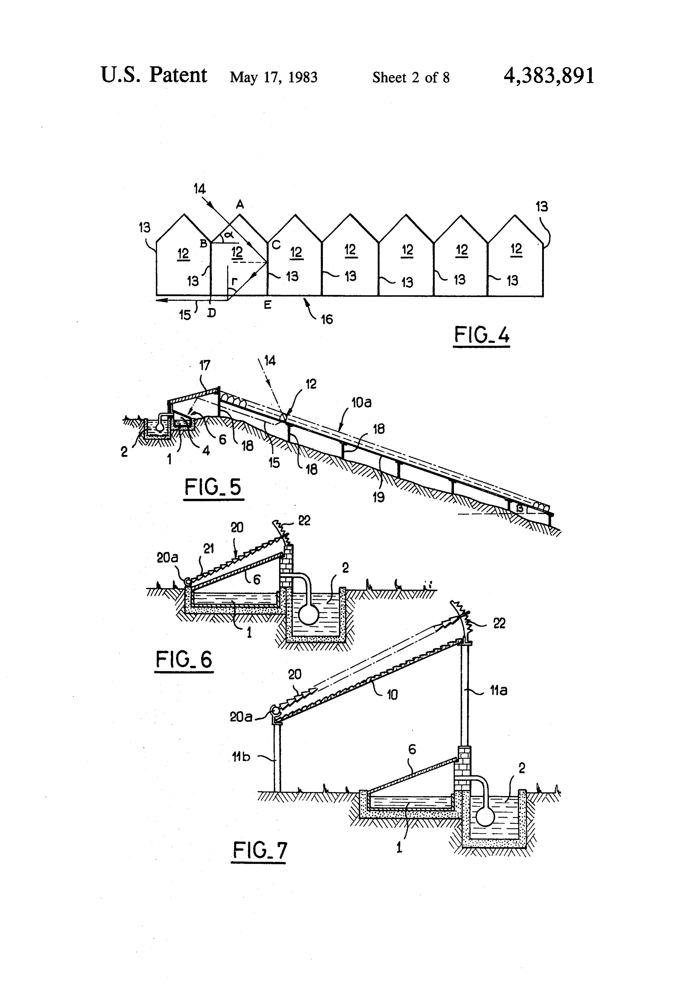
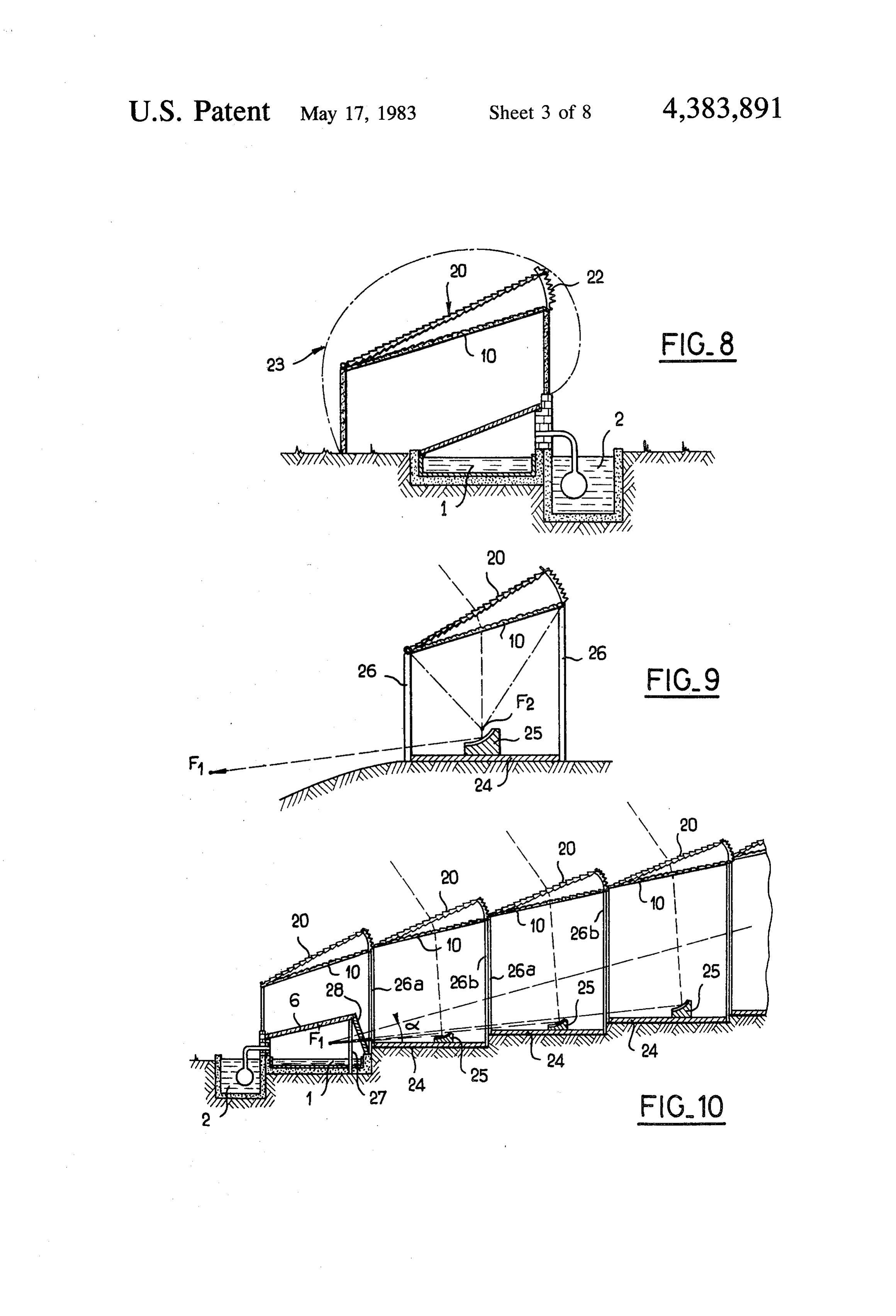
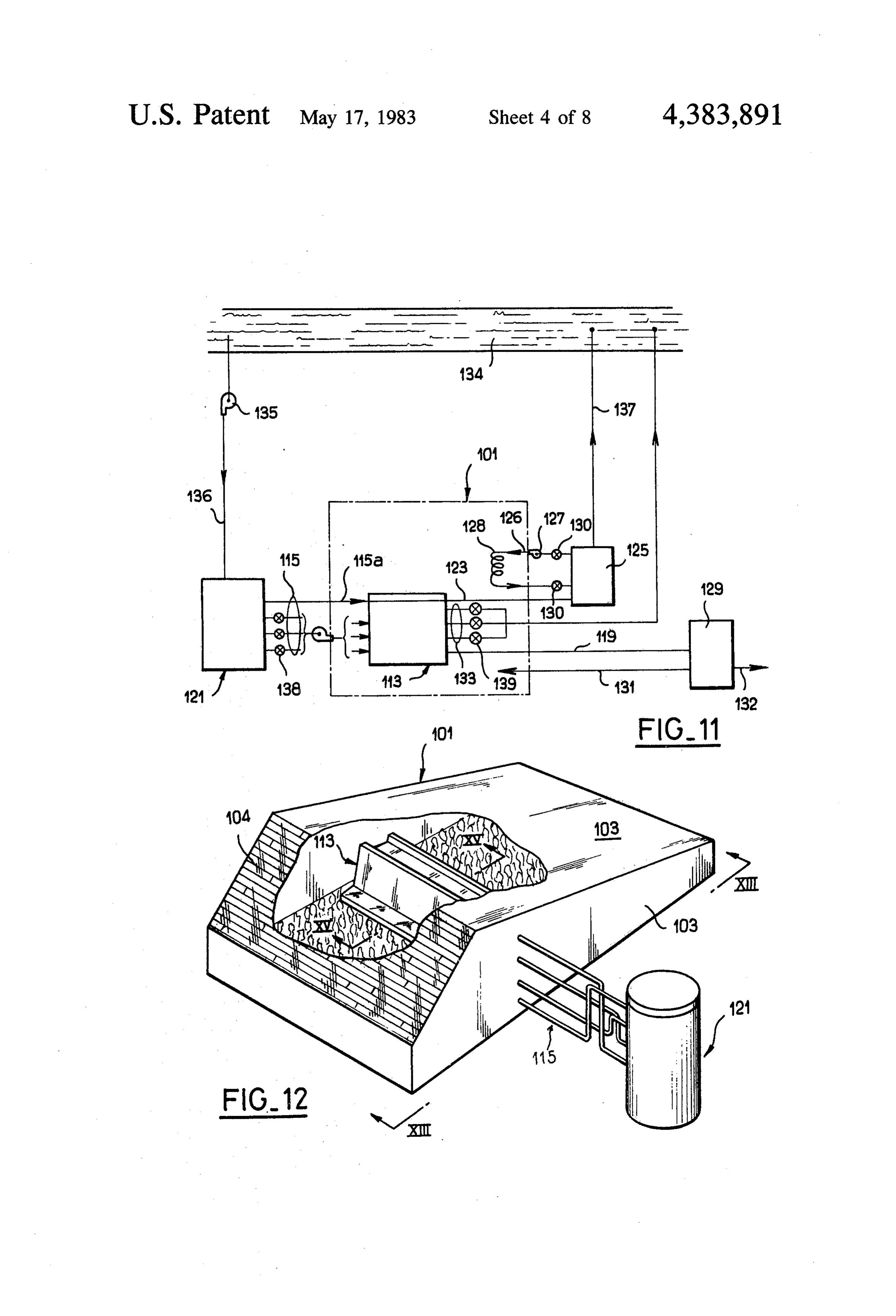
FIG. 3 is a transverse sectional view of an alternative 2 (for instance at the bottom) so as to form a condensa embodiment of the aforesaid device, which increases tion structure. The condensed fresh water is capable of the output; flowing within the pipe 9 under the action of gravity to . . FIG. 4 is a transverse sectional view of a panel made a storage tank (not shown) and of accumulating within up of prisms for focusing the sun's rays; 5 this latter or alternatively of flowing through said pipe FIGi. 5 is a transverse sectional view of a desalting to a series of smaller storage tanks which are placed at device provided with a solar energy focusing structure intervals along its length and are capable, for example, which makes use of panels such as those shown in FIG. of performing the function of constant level tanks at the 4; . . . . . . . . . . . head of underground irrigation ducts, in accordance ;: FIG.6 is a transverse sectional view of an alternative O with arrangements provided in particular in the process embodiment of a device of the type shown in FIG. 2; designated as BIP by the French Company known as iFEG.7 is a transverse sectional view of another alter Bertin.
native embodiment of a device of the type shown in The canal 2 has an open top so that the seawater FIG. 3; . . . . . . . . . . . contained therein remains at a temperature defined by FIG 8 is a transverse sectional view showing a vari 15 the ambient temperature and the evaporation which it ant of the preceding embodiment; produces. The canal capacity can be chosen so as to FIG. 9 is a transverse sectional view of another struc minimize the water temperature under the environmen ture for focusing solar energy; tal conditions which are encountered. If so desired, the FIG. 10, is a transverse sectional view of a desalting wall 7 can be fitted with any additional screen in order device which makes use of structures of the type shown to protect the canal 2 against the sun's rays. in FIG. 9; A plant of this type makes it possible to obtain 3 cubic FIG. 11 is a general arrangement diagram showing meters of fresh water per day and per kilometer of canal the circulation of the water within a device for condi in the case of a canal 1 having a width of 1 meter. As a tioning the atmosphere of a greenhouse according to basis of reference in the field of agricultural irrigation, 1 the invention; 25 liter/second/hectare per sunshine hour is required for ; FIG. 12 is a general view in perspective showing a flood irrigation, namely about 2 liters/day/m2. A more greenhouse equipped with a device of this type; up-to-date sprinkler irrigation system (such as the BIP FIG. 13 is a sectional view taken along line XIII-X- process mentioned earlier, for example) makes it neces III of FIG. 12; . . . . v. sary to employ only 30% of this quantity, namely 0.6 FIG, 14 is a view in elevation of the reservoir for the 30 liter/day/m2. The device herein described accordingly storage of brackish water; permits irrigation of 5 m2 per-meter of canal. The device FIG. 15 is a sectional view taken along line XV-XV would also be capable of meeting the fresh water re of FIG. 12 and showing the evaporator; quirements of one person per meter of canal. FIG. 16 is a view taken along line XVI-XVI of A method adopted with a view to obtaining better FIG. 15 and showing the evaporator; 35 results consists in focusing solar energy. FIG. 3 shows I. FIGS. 17 to 19 illustrate alternative embodiments of the system of FIG. 2 to which there has been added a the device for focusing solar radiation; solar energy focusing device fabricated from panels 10 FIGS. 20 and 21 illustrate alternative embodiments of of transparent material each having a molded external the conditioning device. . . . . . face (or internal face or even both faces) so as to form a The canal layout of a desalting device-shown in FIG. 40 Fresnel lens which focuses the sun's energy inside the 1 makes. provision for two canals 1 and 2 linked by greenhouse 4.
ordinary manually, operated sluices 1a, 1b, 2a, 2b, to a Panels of this type can be made from plastics, for canal 3 or to a pipe fed with seawater or brackish water. instance from methacrylic resins, and formed into a The pressure drop along the canal 3 should be sufficient cylindrical Fresnel lens by molding. The grooves pro to cause seawater to flow along the canals 1 and 2 sim 45 viding the lens effect extend horizontally in a direction ply by opening the head sluices 1a and 1b and the foot parallel to the canal 1. The slope given to the panels 10 sluices 2a and 2b. Closing of these sluices has the effect is the same as the slope given to the panes 6. It will thus of trapping the water within both canals 1 and 2. be ensured that the annual mean direction of the sun's The canal 1 is intended to be the heat source or water rays at noon will be at right angles to the panels 10. evaporation canal whereas the canal 2 is intended to be 50 During the daytime the sun's rays will remain more or the cold source for a structure on which fresh water less within a plane at right angles both to the panels 10 evaporated from the canal 1 is to be condensed. and to the vertical cross-section of the canals 1 and 2. In : As shown in FIG. 2, the bottom and sides of the canal this manner, focusing of the rays will continue to take 1 are provided with a radiation-absorbent coating (for place within the greenhouse 4.
instance a coat of black paint). The canal is embedded in 55 By reason of the fact that the distance between a a refractory layer made for instance of sand or bricks. panel 10 and a greenhouse 4 must be of the same order The canal is enclosed and topped by a transparent as the width of said panel 10 (which is the distance AB), pane 6 of glass, for instance, and placed slantwise either the height of the structure supporting the panel 10 may in order to ensure that the surface-of said pane is orthog become substantial, even though said support structure onal on the average to the sun's rays at noon (the angle 60 may be limited in principle to posts 11a, 11b braced by of slant of the pane varies with the latitude) or in order cross-members in the form of L-section bars 11c on to satisfy other conditions mentioned later. which the panels are brought to bear. A wall 7 which supports the higher end of the pane 6 The wall 7a between the two canals can be made is made of refractory material (such as bricks). higher, however, so that its shadow may thus protect The general arrangement described thus far consti 65 the canal 2 from the sun.
tutes a greenhouse structure over the canal 1. At night, it is advisable to unroll or place screens, * The wall 7 is pierced with holes for pipes 8 which awnings or any kind of protective sheet such as a tar connect the canal 1 to a pipe 9 placed within the canal paulin above the panes 6 in order to minimize losses by 12 radiation within the greenhouse. This could also be the losses through the screen and the losses through the done in the case of FIG. 2. . pane 6 when the solar rays do not strike the screen at A device of the type shown in FIG.3 permits irriga right angles. Such screens can be formed by molding tion of 25 m per meter of canal (assuming that the canal from plastic material and the same applies to the panels 1 has a width of 1 meter) or makes it possible to satisfy 10 which perform the function of a Fresnel lens. the fresh-water requirements of four to five persons per Arrangements can be made to support and maintain meter of canal. - the screens in position by means of a frame which en There is shown in FIG. 4 another device for focusing dows them with the necessary mechanical properties. splar energy which is of greater capacity. This device is As shown in FIG. 7, a screen 20 of this type can also also constructed in the form of panels. Each panel is 10 be used in conjunction with a panel 10 having the func made up of elongated cells 12 as shown in cross-section tion of a Fresnel lens (mounted as shown in FIG. 3) so in FIG. 4 and the vertical walls. 13 of said panels are that the sun's rays will continue to strike the panel 10 at metallized (made reflecting). The sun's rays at noon right angles throughout the year. - enter the transparent material of each cell at right angles In both the cases of FIG. 6 and FIG. 7, the angle of to the face BA. The face AC is at right angles to the face 15 slope of the pane 6 and/or of the panel 10 which constis BA so that it cannot interfere with the sun's rays which tutes a Fresnel lens will be chosen so, as to ensure that strike the next cell. The angle a made by the face BA the sun's rays at noon, on the longest day of the year, with the horizontal line BC is chosen so that the sun's will be at right angles to the pane 6 and/or to the panel rays 14 are refracted for the most part at the face DE, 10; at that time, it will be necessary to remove the along that face. Thus the angler must therefore corre 20 screen 20. During the rest of the year, when the sun at spond substantially to the Brewster conditions, which noon is lower in the sky, the screen will be used and means that, if n is the refractive index of the cell mate placed at an angle of slope which will always be larger rial, a =arcsin (1/n). Since the refractive indices vary than the angle given to the pane6.or the panel 10. only to a slight extent (between 1.4 and 1.6), it is appar FIG. 8 relates to a solution of the same type as the ent that a is of the order of 45 (which is the correct embodiment of FIG.7 but differs from this latter in size, value when n=1.414). particularly insofar, as the width of the panel 10 which Panels of this type consequently bend part of the solar constitutes a Fresnel lens is, for example, only twice the energy in a given direction 15 along their bottom-sur width of the pane 6. It is accordingly proposed in this face 16. . . v case that, instead of erecting wood frames or even FIG.5 corresponds to a layout of a desalting device 30 walls, the overall optical structure (by which is meant which employs the solar focusing means shown in FIG. the panel 10 and its support) can form a kind of casing 23 which can be transported either as a kit or pre-assem
After passing through the cells 12, the solar rays such bled. Thus, in the case of a canal having a width of 50 as the ray 14 are bent in a direction parallel to the bot cm, for instance, the dimensions of the casing will be of tom face of the panels 10a. Said rays then impinge upon 35 the order of one meter.
a reflecting roof (mirror) 17 and enter" . the canal 1 through the pane 6.
A reduction in size of the panel 10 which forms a
Fresnel lens can also lead to another device for focusing
The solar focusing device is supported above ground solar energy as shown in FIG. 9. This casing is such that by a very light structure comprising poles 19 intercon its dimensions can also be of the order of one meter, for nected by beams 19 which remain in the plane of the 40 example, and includes a floor 24 on which is mounted figure, thus avoiding the presence of beams parallel to an elliptic mirror 25. Thus the solar energy focused at the canals, which would intercept the rays bent as indi F2 by the panel 10 acting as a Fresnel lens and by the cated. .. . screen 20 is reflected from said elliptic mirror and refo The angle of slope (3 is chosen so as to ensure that the cused to a further focal point F1. solar rays are at right angles to the incident faces of the 45 Whereas the faces of the casing parallel to the plane cells when the sun is at the zenith. The slope would be of the figure can be full, the faces located at right angles zero in the case of rays which are inclined to the hori to the plane of the figure (at least the face directed zontal at an angle of 45°; the angle of slope is 15 in thetowards the focal point Fi) must be hollow so that the case of rays inclined to the horizontal at 60", and is 25 upright members designated by the references 26a, 26b in the case of rays inclined to the horizontal at 70. 50 usually consist of posts.
Refractory material 20 is placed behind the mirror 17 In the case of a device of this type, a certain degree of in order to form a screen and thus protect the green accuracy is necessary and the screen 20 must accord house against radiation losses within the canal 1 during ingly be considered as an essential element in order to the night. s ensure useful operation of the device throughout the Another solution for focusing solar energy as shown 55 year. In the event that the focal point F1 is intended to in FIG. 6 consists in compensating for the annual varia be located beneath the pane 6 within the canal 1, its tion in the sun's altitude by means of a screen 20 formed position can have dimensional variations of the order of of prisms 21. By following a precise calendar schedule, 50 cm which, over a range of 20 meters, results in a one can either change screens such as the screen 20 or in possible angular tolerance of less than 2'. other words make use of screens consisting of prisms 60 As shown in FIG. 10, a number of casings of the type having different apex angles, or adjust the angle of slope shown in FIG. 9 can accordingly be employed for the of the screen. To this end, arcuate mounts 22 can be purpose of focusing the solar energy collected over a attached to the wall 7 and provided with notches in very large surface area to a point F1 which is located which the screen can be engaged according to the de within the canal 1 beneath the pane 6. The shape of the sired angle of slope, said screens being pivotally 65 roof of the greenhouse over the canal 1 is somewhat mounted at 20a. The number of operations involving modified to permit entry of the sun's rays collected by changes of screens or changes of screen angles in the the casings. Thus the poles 27 which support the pane 6 course of a year can be computed, taking into account at intervals and are interconnected at their upper ends 13 also support another substantially vertical transparent receive the condensed water formed on the compart pane 28. Furthermore, the casings for focusing solar ment walls. Said gutters are connected to discharge energy are placed in such a manner as to ensure that no pipes 118 which are gathered into a single discharge casing obstructs rays which emanate from casings that manifold 119. In order to obtain satisfactory removal of are further away. condensates, the plates 116 and the gutter 117 are down The necessary precision for the device can be ob wardly inclined towards the evaporator wall nearest the tained at the factory before transportation to the site point of connection of the pipes 118 (as shown in FIG. location. To this end, the upright members 26a, 26b of 16).
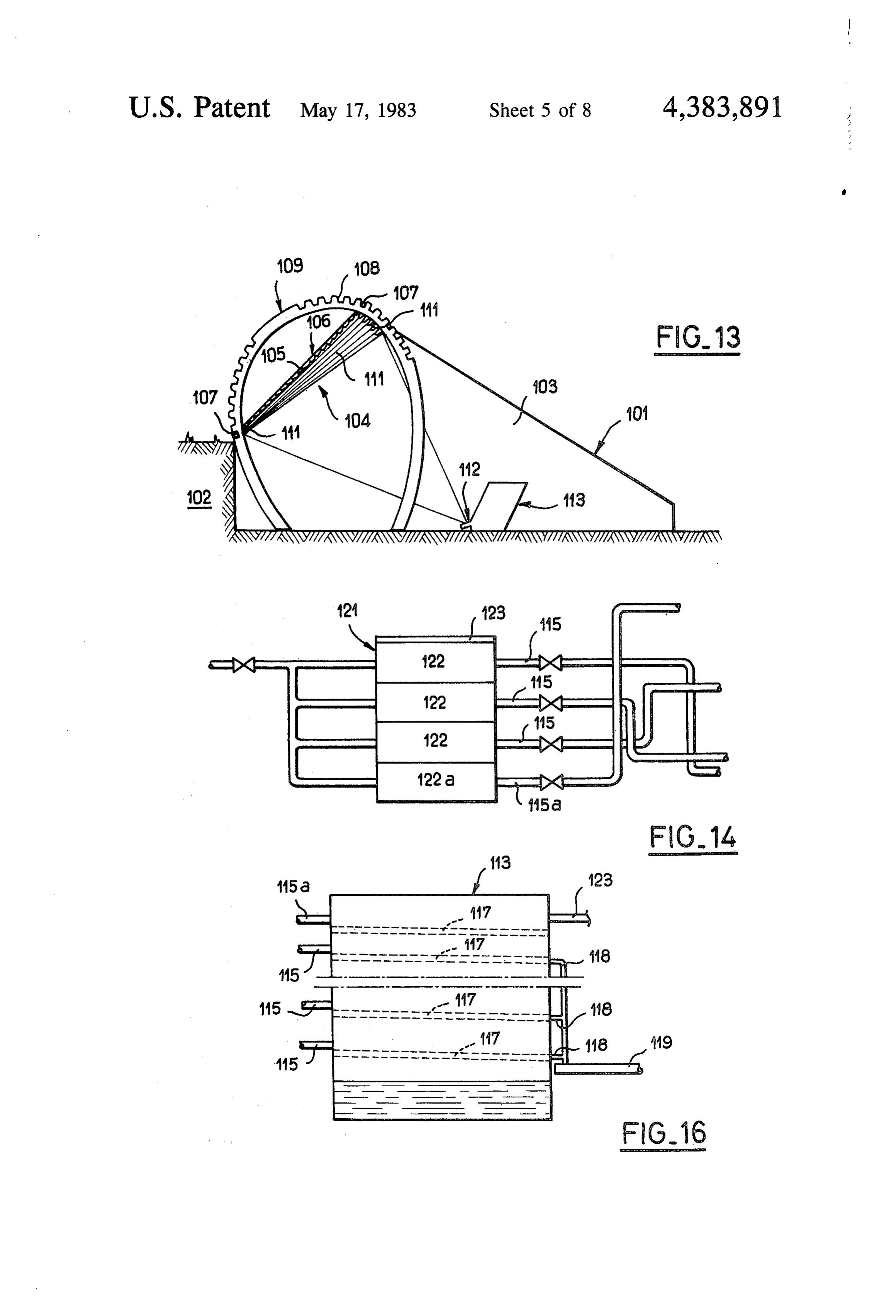
adjacent casings will be provided with notches or holes The pipes 115 which feed the compartments 114 are for screws or with any other means such that it would O connected to a tank 121 for the storage of brackish prove impossible to place the casings in relative posi water (as shown in FIGS. 11, 12, 14). Said storage tank tions which are different from the intended arrange is exposed to the sun and is divided into a predetermined ment. number of compartments 122 arranged in superposed The angle a for the rays entering the canal 1 can be of tiers. The top portion of the storage tank is covered the order of 20' and the number of casings which can be 15 with a removable transparent sheet 123 which can be placed along a direction at right angles to the canal, replaced at night by an opaque sheet. It is understood although limited, may easily reach 20. that, under these conditions, the temperature of the Referring now to FIGS. 11 to 21, a similar device for water stored within the successive compartments will desalting brackish water will now be described, the progressively decrease from the top to the bottom com desalting device being employed in conjunction with a 20 partment. The layout of the pipes 115 is such that the device for conditioning an enclosed area such as a water flows from the bottom compartments 122 of the greenhouse. storage tank 121 to the top compartments 114 of the A greenhouse 101 (as shown in FIGS. 12 and 13) is evaporator 113.
partially buried in the ground 102 and the side walls 103 In particular, the bottom compartment 112a which of said greenhouse are partly or wholly constituted by 25 contains water at the lowest temperature is connected transparent walls. One side wall 104 is oriented in the to the single top compartment 114a of the evaporator direction of maximum height of the sun during the day 113.
time at the geographic location considered, namely The operation of the evaporator 113 in conjunction towards the south in the northern hemisphere and with the feed system will now be explained. It will be towards the north in the southern hemisphere. 30 assumed that the brackish water has been stored during Said wall 104 comprises an optical focusing structure an entire day within the storage tank 121 and has been 106 formed by a cylindrical Fresnel lens 105 in order to subjected to differential heating as indicated in the fore focus the solar radiation at a point within the green going. During the following night, the brackish water house which will be defined hereinafter. has been protected against cooling during the night by In order to take into account the variations in said 35 means of the opaque sheet.
maximum height during the year, the structure 106 is The following morning, the compartments 114 of the adjustable. To this end, said structure is fixed on two evaporator are filled with a predetermined quantity of bars 107 which extend in the east-west direction and the water corresponding substantially to the quantity which ends of which are adapted to engage in notches 108 of may be evaporated during the day.
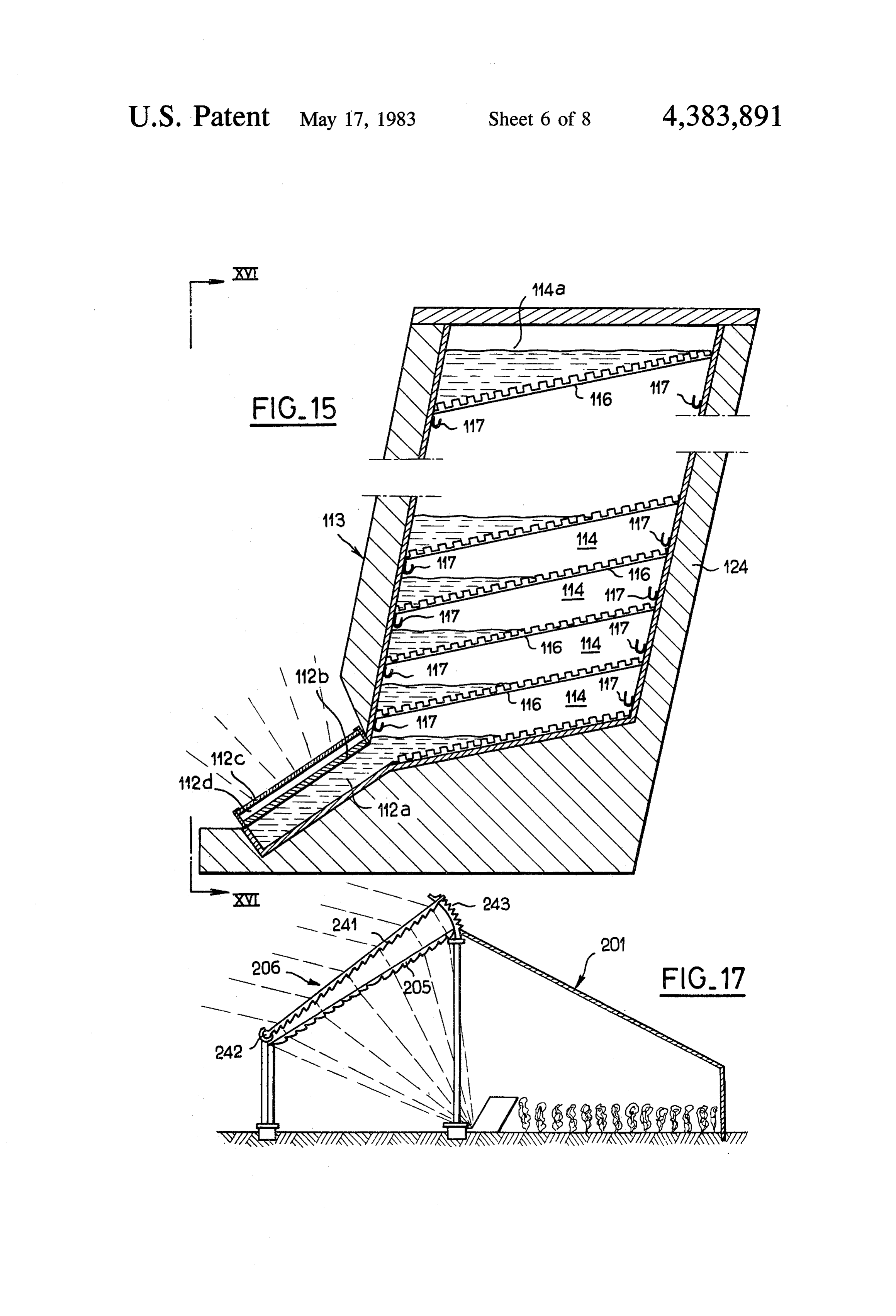
curved supports 109. It is apparent that, by making a 40 The bottom compartment which is adjacent to the suitable choice of notches 108, the orientation of the target 112 is heated to a relatively high temperature. structure 106 can be varied within the limits corre The water contained therein evaporates and condenses sponding to the variations in maximum height of the sun on the plate 116 which is placed above said bottom during the year. compartment and which is heated to a lower tempera In order to close the greenhouse 101 while taking into 45 ture, and yields its heat of condensation to said plate, account the mobility of the structure 106, the four sides thus heating the compartment located directly above. of the lens 105 are attached to the greenhouse 101 by The temperatures within the evaporator therefore de means of bellows seals 111. crease from the bottom upwards in a stepped sequence. The above-mentioned point of convergence of the The evaporator. 113 as a whole is naturally sur solar radiation is a target 112 located at the base of an 50 rounded by a heat-insulating packing 124, with the ex evaporator 113 (as shown in FIGS. 15 and 16). Said ception of the target 112.
evaporator has a certain number of compartments 114 The water within the top compartment 114a is not which are placed in superposed relation and to which a stagnant. On the contrary, a stream of cold brackish predetermined quantity of water is intended to be sup water which flows upwards from the bottom compart plied by means of pipes 115 at the beginning of the day. 55 ment 122a of the storage tank 119 is circulated continu The compartments 114 are separated from each other ously through the top compartment prior to discharge by plates 116 which are grooved in order to improve via a pipe 123.
heat transmission caused by condensation from one The presence of the differential-heating storage tank stage to the next. Said compartments are downwardly 121 therefore makes it possible to preheat the water to inclined towards that wall of the evaporator which is be evaporated in a stepped temperature sequence corre located nearest the target 112 (as shown in FIG. 15). sponding approximately to the sequence within the A bottom compartment is provided with an extension evaporator.
112a covered with an absorbent plate 112b so as to The pipe 123 for the discharge of brackish water constitute the target 112. Moreover, the plate 112b is which serves to cool the evaporator is connected to a surmounted by a pane 112c in which is trapped an air tank 125 for the storage of reheated brackish water, this layer 112d. tank being of a standard type and shown diagrammati Within each compartment, a gutter 117 is placed cally in FIG. 11. A closed-circuit pipe 126 is connected around the periphery of each compartment in order to to said storage tank 125 and fitted with a pump 127 for 14 supplying a circuit 128 which serves to heat the green These results are obtained with a remarkable econ house 101 and can be either isolated or put into service omy of means. In fact, although pumps have been men by means of cocks 130. tioned in the foregoing, it is endeavored to ensure that The fresh-water discharge pipe 119 is connected to a water circulates in particular under the action of grav storage tank 129 of standard type (as shown in FIG. 11) 5 ity. Similarly, valve equipment is minimized and need from which extend a pipe 131 for sprinkling the soil of consist only of valves 138 on the feed side of the evapo the greenhouse and a pipe 132 for normal water con rator and of valves 139 in the flushing-out pipes 133. sumption. Furthermore, the orientation of the optical focusing Provision is also made for pipes 133 (shown in FIG. 10 structure 106 remains unchanged during the daytime 11) which are connected in each case to one compart since the target 112 should be of sufficiently large area ment 114 of the evaporator 113 and serve to discharge to receive the focused energy at all hours. Although this the rinsing water employed for the removal of salt de is attended by slight imperfection in the collection of posits after evaporation. solar rays, the economy thus achieved in capital cost Referring mainly to the diagram of FIG. 11, the gen 15 and labor is substantial. It is only at different seasons eral operation of the installation described in the forego and over fairly long time intervals that this orientation ing will now be explained. is modified as a function of variations in height of the A reserve supply of brackish water is provided by a S.
watercourse 134. In the early morning, brackish water A numerical example of the method will now follow. is drawn from said watercourse by means of a pump 135 The numerical data given hereinafter relate to 1 square in order to fill the brackish-water storage tank 121 by 20 meter of collected solar radiation. means of a pipe 136. The thermal power collected over an area of 1 square After a full day of exposure to sunshine beneath the of meter is 800 watts. Postulating a mean daily efficiency transparent sheet 123, the water has heated differen does 84% in the case of the optical focusing device (which tially within the different compartments 122 of the stor 25 matelynot675 follow the sun in its height variations), approxi W remain available on the target.
age tank. Said tank is then covered with an opaque sheet In practice, the heat-absorbing surface of the target is in order to prevent cooling during the night.
The following morning, the brackish water is trans coveredto with a glass plate which provides an air layer in ferred from the compartments 122 of the storage tank order prevent losses by convection. This results in losses by conduction of approximately 175 W. The 121 into the compartments 114 of the evaporator 113, 30 useful power which therefore remains is 500 W corre each compartment 114 being intended to receive the sponding to an energy of 14.4X 10°joules during eight quantity of water which is intended to evaporate during hours of daylight.
the daytime. The tank 121 is then re-filled with brackish This energy serves to heat and evaporate the water water in order to prepare the cycle for the following within the evaporator 113. Assuming that the evapora day, 35 tor has seven evaporation compartments 114, that the The water which lies stagnant throughout the day water within the target is heated to 90° C. and that the time within the compartments 114 evaporates under the coolant water is at a temperature of 20 C., the rate at action of the solar radiation which is focused by the which fresh water is produced by condensation is 25 structure 106 onto the target 112 and is then recon liters per day.
densed under the action of the cold source constituted It is usually acknowledged that indoor cultivation by the stream of brackish water which flows continu calls for irrigation of 0.6 liter per day and per square ously through the top compartment 114a. meter of cultivated ground area. If the entire quantity of This stream of brackish water is thus reheated, then fresh water produced is employed for irrigation pur stored in the tank 125 in order to reheat the surrounding poses, it is therefore possible to cultivate 42 square me atmosphere of the greenhouse during the following 45 ters per square meter of collected solar radiation, which night by means of the circuit 128. At the end of the is considerable. It will therefore be possible in many night, the water is discharged into the watercourse 134 cases to employ part of the fresh water for other pur through a pipe 137. poses.
Fresh water is continuously collected by means of the The walls 103 of the greenhouse are not exposed to pipe 119, stored within the tank 129, then recirculated 50 direct solar radiation, with the result that the tempera via the pipe 131 for irrigation of the greenhouse or via ture remains at a moderate value of the order of 30 C. the pipe 132 for any other purpose. Should this temperature tend to rise, it would only be At the end of the day, the compartments 114 of the necessary to increase the rate of flow of cold water evaporator 113 practically contain nothing except salt. through the greenhouse in order to remove the excess A certain quantity of water is drawn from the storage 55 thermal energy, this being achieved by employing the tank 121 and injected into said compartments in order to closed circuit 128, for example.
driveout the salt by flushing, the product of this flushing The thermal energy of 14.4x 10⁶ joules extracted by operation being discharged to the watercourse 134 via the cold water stream of the evaporator is stored in the the pipes 133. form of hot water within the tank 125. The invention therefore makes it possible to carry out Calculation shows that, in the case of a sevenstage both the production of fresh water and climate control evaporator, the quantity of coolant water which is nec of the greenhouse. In fact, the greenhouse walls 103 are essary for a period of eight hours is approximately 100 protected against direct radiation of the sun. In regard cubic meters. Such a quantity can readily be stored and to the heat introduced as a result of direct radiation of the water is in fact at a temperature of 30' C. the sun, this heat is partly or wholly removed by the 65 Recirculation of the water during the night hours (14 stream of water which flows through the compartment hours, for example) makes it possible to heat the air 114a. The degree of humidity is controlled by setting from 10 C. to 20 C., thus effectively compensating for the irrigation flow rate at the requisite value. cooling during the night.
Page 15scan →
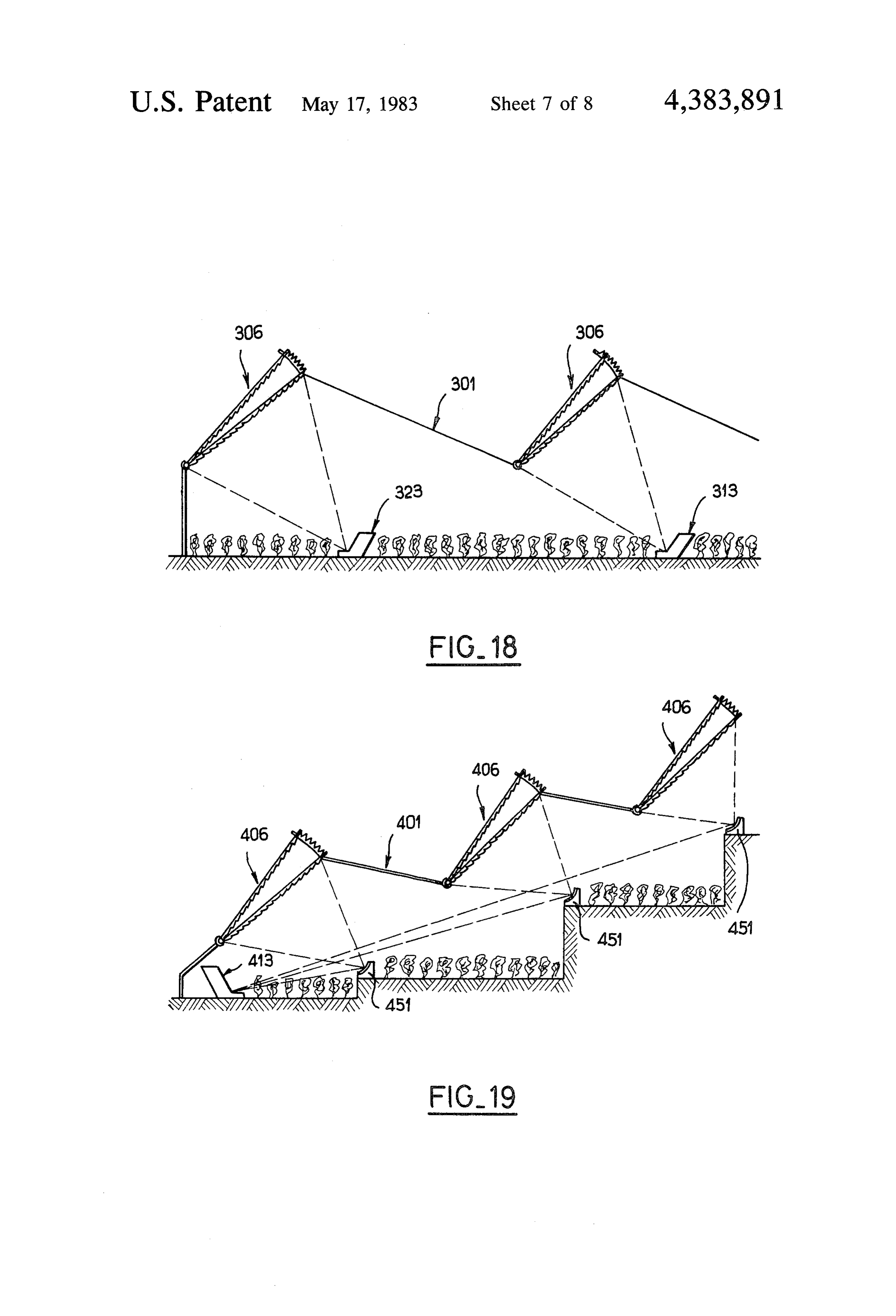
As described earlier and as shown in FIG. 17, an extracting means and for discharging the coolant alternative form of construction of the focusing struc liquid to the exterior of the enclosed space so that ture 206 may be devised. Thus a stationary lens 205 is the coolant liquid is heated during its passage associated with a system of prisms 241 which is capable through the enclosure to thereby enhance conden of displacement about a pivot 242 and can be adjusted sation of the evaporated water and remove the by means of a toothed rack 243 in order to carry out a energy of the intercepted solar energy and transfer variable deviation of the solar radiation, depending on same to the exterior of the enclosed space. the season. This structure is more costly but avoids the 2. An apparatus according to claim 1, wherein said use of bellows elements. apparatus comprises means exterior of said enclosed If the greenhouse 301 is intended to have very sub space for storing the heated coolant liquid after dis stantial ground dimensions, provision can accordingly 10 charge from the enclosed space, means for re-circulat be made for a number of focusing structures 306 (as ing said heated coolant liquid in a closed circuit within shown in FIG. 18), each structure being adapted to the enclosed space, and a system of switching valves for cooperate with an evaporator 319. opening said re-circulating means. In accordance with an arrangement contemplated in 3. An apparatus according to claim 2 or 1, wherein the foregoing, each focusing structure 406 can be the wall means includes a wall forming said optical adapted to.cooperate with a common evaporator 413 by means, said wall forming an optical focusing structure causing all the rays focused by means of mirrors 451 to orientable in the direction of maximum height of the sun converge towards a single evaporator 413. during the daytime.
The method according to the invention can also be 4. An apparatus according to claim 3, wherein the carried into practice by means of simplified devices. 20 optical means comprises a system of prisms, and adjust Referring to FIG. 20, a greenhouse 501 comprises a ing means certain number of focusing structures 506 which are with respectfortovarying the angle of slope of said system the horizontal.
similar to those described in the foregoing and serve to 5. An apparatus according to claim 1, wherein the focus the solar radiation on a corresponding number of optical means comprises a Fresnel lens. open canals 561 in which a stream of brackish water circulates. The evaporation produced within the canals 25 tem6. of An apparatus according to claim 5, wherein a sys prisms is placed in front of the Fresnel lens.
has the effect of humidifying the atmosphere of the greenhouse. The soil is accordingly humidified partly apparatusapparatus 7. An according to claim 1, wherein said comprises a predetermined number of optical by hygroscopy from the moist atmosphere and partly focusing structures, each structure being equipped with by water in the liquid state resulting from recondensa a mirror located at the focal point and oriented so as to tion on the greenhouse walls 503 which are not directly deviate the focused energy towards the enclosure exposed to solar radiation. .
In a more highly improved embodiment (shown in which contains the mass of brackish water. 8. An apparatus according to claim 1, wherein the
FIG 21), a transparent sheath 671 is arranged above the enclosure containing the brackish water comprises an canal 661 and forms two lateral canals 672 for collecting evaporation enclosure having a predetermined number the freshwater which has recondensed on the internal 35 of compartments placed one above the other and each wall of the sheath. Underground ducts, 673 distribute this water for the purpose of irrigation of the green intended to contain a predetermined quantity of brack house. . . . ish water, the bottom compartment being located so as In these simplified embodiments, no provision is to receive the focused solar energy, a circulation canal made for collecting fresh water for general use. for the coolant liquid being located in the top compart Conversely, the embodiments described in the fore 40 providingment, said means for circulating including means for a separate supply of brackish water to each going are not solely applicable to greenhouses but can serve to condition all types of enclosed areas, premises compartment, said heat extracting means including con or rooms and especially workshops while at the same densation means for condensing the evaporated water time providing a supply of fresh water. within each compartment, and said collecting means What is claimed is: 's : . 45 including means for collecting and discharging the con 1. Apparatus comprising means for decreasing the densed water to a fresh water storage tank.
rate of temperature increase in an enclosed space while 9. An apparatus according to claim 8, wherein a obtaining purified water from brackish water including: brackish water storage enclosure exterior of said en wall means for defining an eclosed space; closed space is provided for supplying the enclosure optical means for intercepting solar energy impacting 50 and comprises at least two compartments, and wherein on a portion of said wall means and for focusing the one of said compartments is exposed to solar radiation intercepted solar energy in a focused region within and connected to lower compartments of said enclosure ... the enclosed space so as to prevent uncontrolled whilst another of said compartments is not exposed to heating of the enclosed space by the intercepted solar radiation and connected to upper compartments of solar energy; . .. 55. said evaporation enclosure.
an enclosure totally encompassed within the enclosed 10. An apparatus according to claim 9, wherein the space and containing brackish water, a portion of storage enclosure is provided with a removable opaque the brackish water lying in the focused region so sheet.
that the energy of the intercepted solar energy is 11. An apparatus according to claim 8, wherein the imparted to and heats the brackish water to cause fresh water storage tank is connected to a canal system evaporation therefrom; for irrigating the soil of the enclosed area. heat extracting means within said enclosure for con 12. An apparatus according to claim 1, wherein said tacting and condensing evaporated water; apparatus comprises a predetermined number of optical collecting means for collecting condensed water and focusing structures, each structure being equipped with for removing the condensed water from said enclo an elliptic mirror, one focus of which being located at a sure; and 65 focal point of said focusing structure, and the other means for circulating coolant liquid from a source focus of which being located in the area of said enclo exterior of said enclosed space through said enclo sure containing the brackish water. sure in heat exchange relationship with said, heat k . . x sk
Page 16scan →
United states patent and trademark office
Certificate of correction
Patent no
Dated
INVENTOR(S) : Philippe Clavier it is certified that error appears in the above-identified patent and that said Letters Patent is hereby Corrected as shown below:
on the title page assignee should read -- (73) Assignee: Spie-Batignolles, Puteau, France, a part interest --.
eigned and scaled this
Fourteenth O ay of August 1984
Seal
Attest:
Gerald j. mossinghoff
Attesting Officer Commissioner of Patents and Trademarks
Provenance
- Collection
- Patents citing this work
- Pages
- 16
- Method
- pdftotext (the PDF's own text layer) + pdftoppm 300dpi page scans
- Patent office record
- patents.google.com →
- Source
- Google Patents citing-documents table
- Assignee
- Spie-Batignolles
- Published
- 1983-05-17
- Transcribed from
- patentimages.storage.googleapis.com →