

patent · US4388917A
Triangular solar collector
21 June 1983
Text
Page 1bibliographic recordscan →
United States Patent (19)
(54) TRIANGULAR SOLAR COLLECTOR
Inventor: H. Richard Shea, Jr., 440 Walker
Rd., Great Falls, Va. 22066
51 Int. Cl.................................................. F24J 3/02 52 U.S. C. .................................... 126/450; 126/429;
4,061,129 12/1977 Wilson ............................ 126/436X 4,067,316 1/1978 Brin et al. ... 126/449 X 4,088,266 5/1978 Keyes...... ... 126/449 X 4,138,061 2/1979 Besack .... ... 126/436 X 4,207,868 6/1980 Peterson .. ... 126/436 X 4,257,396 3/1981 Reinert ................................ 126/449
4,294,228 10/1981 Kruger et al. ...................... 126/430 4,304,223 12/1981 Novinger ........................ 126/449 X Primary Examiner-Larry Jones
Attorney, Agent, or Firm-Leitner, Palan, Martin & Bernstein
A solar collector is provided having a substantially triangular-shaped housing defined by a base and a pair of converging side walls. The housing of the collector includes an outlet adjacent the top of the housing, an inlet, a central area and a pair of outer end areas. The problem of stagnation of air in the outer end areas is solved by providing barrier means adjacent the side walls for creating air ducts connecting the outer end areas to the outlet. The intake air is distributed along the base of the collector by an inverted T-shaped air distrib utOr means.
17 Claims, 6 Drawing Figures
Drawings
Page 2drawing sheetscan →
Page 3drawing sheetscan →
Page 4scan →
having a base and a pair of converging side walls. The
TRANGULAR SOLAR COLLECTOR housing includes absorbing means to absorb the incident solar radiation. The front of the housing is covered by a
BACKGROUND OF THE INVENTION panel which allows the radiation to enter the collector. This invention relates to solar heating by convection An air distributor means having an inverted T-shape is and, more particularly, to a triangular-shaped solar used to distribute the intake air along the base of the energy collector. collector. The problem of stagnation in the outer end The concept of using the sun as the source of energy areas is solved by providing a barrier adjacent the side in a heating system is well known. This type of system 10 walls of the collector. In particular, this barrier creates involves collecting incident solar radiation, transferring air ducts which connect the outer end areas to the outlet this radiation into heat energy, and then using the heat of the collector. The ducts prevent the rising air in the energy to heat the inside of a building. The solar radia central area from cutting off the movement of air from tion is collected by a solar collector which typically is the outer end areas to the outlet of the collector. The air installed on the roof or in a window of the building. One ducts include a number of spaced apertures along their common type of prior art solar collector utilizes an is lengths as well as airfoils adjacent these apertures. This absorbing material placed within the collector to collect structure provides for a "venturi-effect' which en the incident solar radiation. The air within the collector hances the air flow out of the collector after the air is then heated by the absorber and delivered to the ducts become heated. The housing includes a connect inside of the building with the aid of a blower. Such a ing plate disposed between the converging side walls system is seen in U.S. Pat. No. 4,100,914. Another com- 20 which includes ports for both the inlet and outlet of the mon prior art collector is the "convection' collector, collector. An air space is provided between the absorb wherein the natural convection currents caused by the ing means and the panel such that the heated air may heating and cooling of the air are utilized to circulate more readily flow through the collector. the air. This type of collector is seen in U.S. Pat. No. The air distributor means includes an air distributor 4,135,490. The natural convection collector offers some 25 conduit having an inlet in the connecting plate, a T-joint advantages over the blower-type collector in that it is attached to the conduit adjacent the base, and horizon generally simpler in design, and doesn't utilize electric tally-lying air tubes extending along the base from the ity.
A problem arises, however, when a substantially Tjoint. their
The air tubes, which include exhaust ports at ends, are each surrounded by a sleeve. A port and triangular-shaped natural convection collector is used. 30 a longitudinal slot are provided in the top of each sleeve In particular, the convection currents will move the air to distribute the air along the base of the collector. The in the central area of the collector since the heated air located there will rise to the relatively cooler air inside port has a large cross-sectional area relative to the lon gitudinal slot and is adjacent the exhaust port in the air the building. However, as the hot air in the central area tube. This structure insures that the outer end areas are rises and exits the outlet of the collector, it cuts off the 35 not suffocated by the central area "grabbing up' the movement of air from the outer end areas of the collec intake air before it reaches the end areas.
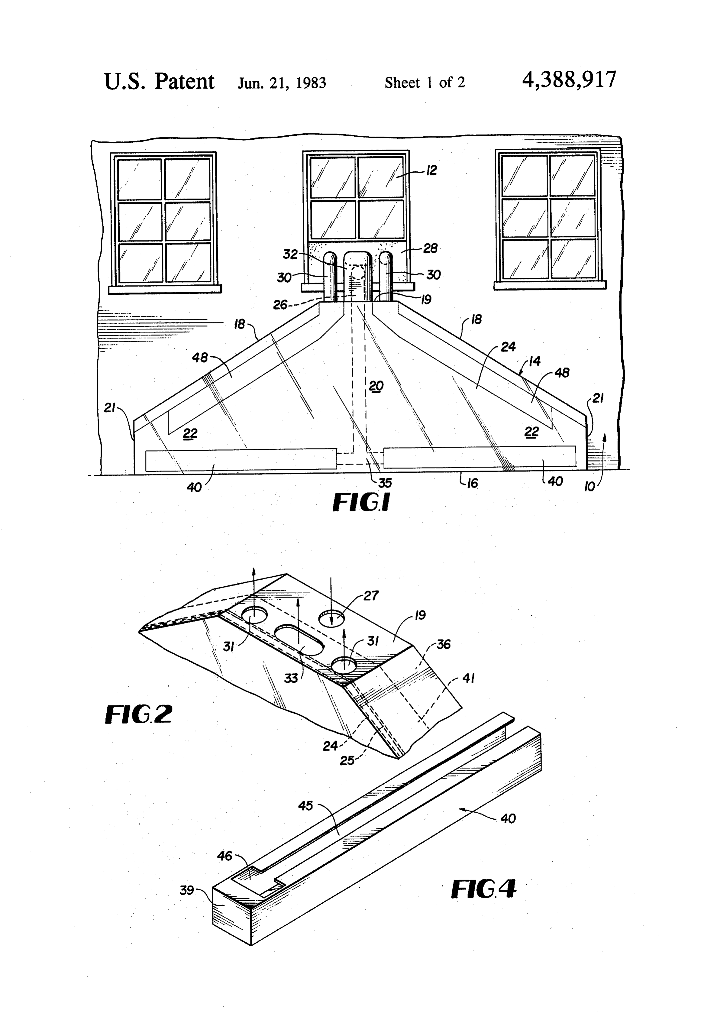
tor to the outlet. More specifically, the air in the outer end areas will not blend with the rising air from the BRIEF DESCRIPTION OF THE DRAWINGS central area since this air is moved by a relatively strong air current which serves to shear the weaker air cur- 40 FIG. 1 is a front view of the collector disposed rents in the outer end areas. This shearing effect causes against a building.
2 is a perspective view of the top of the collec stagnant air pockets to be formed in the outer end areas, tor showing various inlet and outlet ports and the direc which raise the operating temperature of the collector tion of air flow.
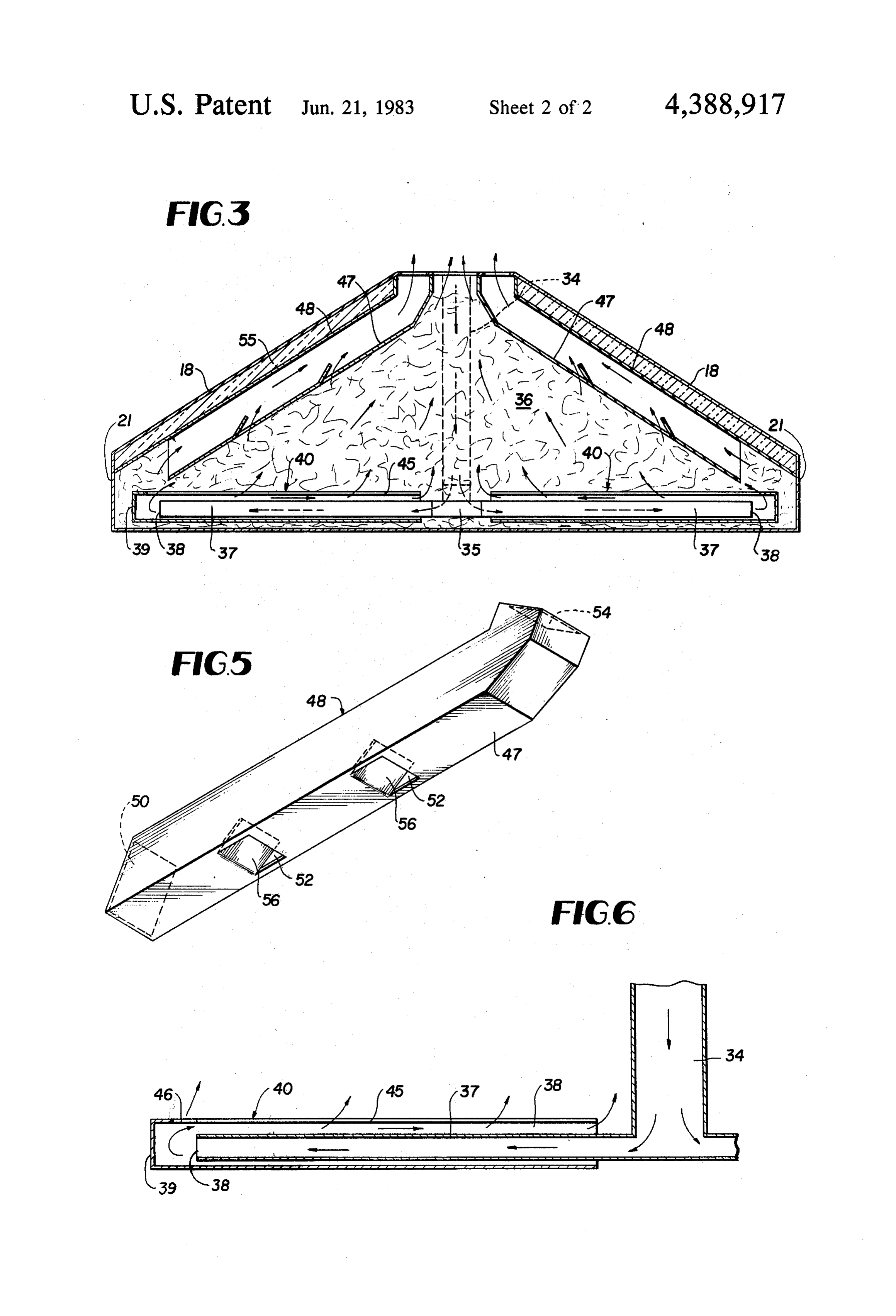
and result in greater heat loss and inefficiency.
Many prior art solar collectors are also uneconomical 45 FIG. 3 is a front view of the interior of the collector in that they require permanent installation on the roof showing the details of the novel structure. or in the window of the building. In particular, it is shown FIG. 4 is a perspective view of one of the sleeves often necessary for the user to physically modify the in FIG. 3.
structure in order to effectively install the collector. FIG. 5 is a perspective view of one of the air ducts These modifications are often extremely costly and 50 shown in FIG. 3.
burdensome. FIG. 6 is a flow schematic showing the air flow through the air distributor means in FIG. 3.
Summary of the invention
Description of the preferred
It is therefore an object of the present invention to EMBODIMENT provide a substantially triangular-shaped solar energy 55 collector of the convection type wherein there is no FIG. 1 shows a portion of a building 10 which in stagnation of air in the outer end areas of the collector cludes a window 12. The collector 14 of the present during any portion of the collector's operating cycle. invention is designed to be disposed against the side of It is another object of the invention to provide a the building 10. The base 16 of the collector 14 rests substantially triangular-shaped solar energy collector 60 against the ground or a suitable foundation thereon. which is designed to be disposed exterior a building, Such a foundation may be made of wood or cement. adjacent a window thereof, and which requires no mod As seen in FIG. 1, the collector 14 has a substantially ification of the building for effective installation. triangular-shaped housing defined by the base 16 and It is a further object of the present invention to pro side walls 18 which converge at a connecting plate 19. vide a collector of the type described which may be 65 The side walls 18 and the base are joined by the end simply produced in modular kit form. walls 21. It is important to the present invention that These and other objects are attained by providing a end walls 21 are relatively short in length compared to collector with a substantially triangular-shaped housing the base 16 such that the collector has a substantially 5 triangular-shape. The collector housing includes three rial 36, such as fiberglass. This material, which is black distinct areas; a central area 20, and a pair of outer end ened to increase its absorption characteristics, prefera areas 22. The central area 20 is defined by the volume of bly covers the interior back and end walls of the collec the collector which lies beneath the connecting plate tor. As best seen in FIG. 2, a layer of air 41 is thus 19. The outer end areas 22 include the remainder of the provided between the absorbing material 36 and the collector's volume. The housing of the collector 14 may transparent panels 24 and 25. This structure is advanta be made out of any suitable rigid material, such as metal geous since the fiberglass, although porous, offers some or hard plastic. The front of the collector is covered by resistance to air flow. The use of the air layer 41 allows a panel 24, which is made from any suitable solar trans the convection currents to move the heated air more parent material, such as glass or plastic. This panel al 10 readily out of the collector. Also, if the collector was lows the incident solar radiation to pass into the interior completely filled with the absorbing material, it would of the collector 14, where it can be absorbed. In the quickly become clogged due to the inherent filtering preferred embodiment of the invention, two transparent characteristics of the fiberglass.
panels are used to prevent heat loss. These panels are Referring back to FIG. 3, the air distributor conduit secured together near the base 16 of the collector by 5 34 is connected to two horizontally-lying air tubes 37 any suitable means. The upper edge of the inner panel adjacent the base 16 by T-joint 35. This joint brings 25 rests against the outlet ports of the collector as seen together the air tubes. Exhaust ports 38 are provided in in FIG. 2 such that a tapered air pocket is formed be the air tubes 37 at their ends. The air tubes 37 lie within tween the panels. This pocket traps any solar energy rectangular-shaped sleeves 40, which are preferably which might otherwise be dissipated to the exterior of 20 made of metal and painted black to improve their heat the collector through conduction. absorption characteristics. The end 39 of the sleeve 40 is It is an important feature of the present invention that spaced from the exhaust port 38 and causes the incom the collector 14 be readily connectable to the building ing air to turn 180 without substantially impeding the 10 for operation. In particular, FIG. 1 shows the air air flow. As seen in FIG. 4, each sleeve 40 includes a pipes which collect the cooler air from within the build 25 longitudinal slot 45 and a port 46 in its top surface. The ing and redistribute the air heated by the collector. As port 46 is adjacent an end wall 21 and has a large cross seen in FIG. 1, a plate 28, which is preferably made of sectional area relative to the longitudinal slot 45. The foam rubber insulation, is provided to fit in the partially slot 45 and port 46 insure that the outer end areas 22 are opened window 12. The air within the building is col not suffocated by the central area "grabbing up' the lected by first air pipe 26, which has an inlet in plate 28 30 intake air before it can reach the outer end areas. and an outlet at the connecting plate 19. As seen in FIG. The above structure defines an inverted T-shape 2, the building air travels through an intake port 27 which allows the cool intake air to be distributed along provided in the connecting plate 19, and flows to the the base 16 of the collector. The blackened metal interior of the collector where it can be heated. Simi sleeves, which may also be cylindrical in shape, serve to larly, the air heated by the collector is distributed into 35 preheat the intake air as it travels along the base 16 of the building by second and third air pipes 30 and 32 the collector.
having inlets in connecting plate 19 and outlets in plate According to another important feature of the pres 28. Second air pipes 30 distribute the heated air from ent invention, a barrier 47 is provided adjacent the side outlets 31 in the connecting plate 19, which are con walls 18 for creating air ducts 48 as shown in FIG. 3. nected to the air ducts 48 along the sides of the collec These air ducts serve to connect the outer end areas 22 tor, to the plate 28. The third air pipe 32 distributes the to the distinct outlets 31 in the connecting plate 19 to heated air from the outlet port 33 in the connecting prevent stagnation of air in the outer end areas when the plate 19, which is connected to the central area 20 of the heated air in the central area rises and cuts off the circu collector, to the plate 28. The outlet ports 31 and 33 lation from the outer areas. As best seen in FIG. 5, each define an outlet in the connecting plate 19 through 45. one of the air ducts 48 includes an inlet port 50 adjacent which air heated by the collector passes. The intake the base 16, a number of spaced apertures 52 in the port 27 in the connecting plate 19 defines an inlet in the barrier 47, and an outlet port 54 fluidly connected to an housing. Although the connecting plate is explicitly outlet 31 in the connecting plate 19. Referring back to shown, the outlet of the collector may be taken from FIG. 3, the side walls 18 have a double panel construc any convenient location adjacent the top of the housing. 50 tion wherein the space between the panels is filled with Also, the inlet of the collector may be disposed in any insulation 55 to prevent heat loss. The ducts 48 are convenient area of the housing. To prevent heat loss, preferably made of blackened metal for increased absor the air pipes 26, 30 and 32 may be enclosed in an insu bency of solar radiation. This structure, along with the lated housing. use of the insulating material 55 in the side walls 18, It should be evident that the above structure provides 55 allows the ducts to store heat during peak hours of a simple, yet efficient method for connecting the solar operation, this heat being released later when the col collector to the building 10. This structure does not lector begins to cool down.
require any modifications to the existing building such Referring back to FIG. 5, airfoils 56 may be provided as is common in many prior art collectors. The use of adjacent the apertures 52 for creating a "venturi-effect' the plate 28 and the various air pipes allows the home 60 in the air flow through the air ducts. In particular, as the owner to install or disconnect the collector with a mini ducts heat up, air moves through at a higher velocity. mum amount of effort. As the air passes around the air foils a back pressure is FIG. 3 shows a more detailed view of the collector created which pulls in more air from below the ducts structure of the present invention. An air distributor 48. This structure thus enhances the circulation of air conduit 34 is connected to the intake port 27 in the 65 throughout the housing after the air ducts become connecting plate 19 to bring the intake air into the col heated.
lector housing. This conduit, which is preferably made The operation of the solar collector of the present of a plastic material, is embedded in an absorbing mate invention will now be explained with reference to the 6 figures described above. Assuming that the air ducts 48 installed with no modification to the existing structure. are not present, the air in the central area will be heated, In view of the above description, it should be seen that rise and exit the collector through the outlet port 33. the several objects of the invention are achieved and This air will then pass through the third air pipe 32 and other advantageous results attained. into the building. Simultaneously, the cooler air from 5 Although the invention has been described and illus within the building will be drawn into the collector via trated in detail, it is clearly understood the same is by first air pipe 26 and the air distributor conduit 34. How way of illustration and example only and is not to be ever, as the heated air rises, it shears the movement of taken by way of limitation. The spirit and scope of the air from the outer end areas of the collector and thus present invention are to be limited only by the terms of stagnation occurs in the outer end areas 22. 10 the appended claims.
To solve this problem, the barrier 47 is provided What is claimed:
adjacent side walls 18 of the collector for the purpose of 1. A solar collector comprising: creating air ducts which connect the outer end areas a substantially triangular-shaped housing having a and the outlet of the collector. In particular, the air base and a pair of converging side walls such that ducts 48 present a barrier to the rising air in the central 15 the width of said housing decreases further from area 20 such that this air cannot shear the movement of said base, said housing including an outlet adjacent air from the outer end areas. The use of the distinct the top of said housing, an inlet, a central area outlet ports 31 in the air ducts 48 allow the outer end generally beneath said outlet, and a pair of outer areas to be connected to the collector outlet without the end areas each spaced apart generally horizontally air within the ducts being subjected to the shearing from said central area;
effect of the rising air from the central area. absorbing means in said housing to absorb incident Once the air in the outer end areas 22 begins to move solar radiation;
up the air ducts 48, it is further heated by the hot air a panel of solar transparent material, said panel being below the air ducts. This is accomplished by the flow of secured to the front of said housing for allowing this air through the spaced apertures 52 in the barrier 25 said incident solar radiation to pass through said 47. The barrier prevents further stagnation when the air panel to be incident upon and absorbed by said rising through the apertures would otherwise tend to absorbing means;
shear the air from the outermost end areas of the collec air distributor means for distributing cool air from tor, by always providing a connection between all por said inlet along said base of said housing; and tions of the outer end areas of the outlet. 30 barrier means inclined from the vertical and adjacent The ducts begin to heat up during the peak hours of said converging side walls for creating air ducts operation due to their blackened surfaces and the adja connecting said outer end areas to said outlet to cent absorbing material 36. The air foils 56 help create prevent stagnation of air in said outer end areas. a "venturi-effect' in the ducts 48 to enhance the flow of 2. A solar collector as defined in claim 1 wherein each heated air out of the collector during this time. Specifi 35 of said air ducts includes an intake port adjacent said cally, as the ducts heat up, the air velocity also rises. As base, a number of spaced intake apertures in said barrier the air passes over the foils 56, a back pressure is devel means along the bottom surface thereof, and an outlet oped which pulls in more air from below the air ducts port at said outlet.
48, thus improving circulation. Any residual heat stored 3. A solar collector as defined in claim 2 wherein each in the air ducts during these peak hours is released when 40 of said air ducts further includes air foils adjacent said the collector begins to cool down. This feature insures spaced intake apertures and interior of said air ducts to that the building will continue to be heated for some create a venturieffect in said air ducts to enhance the air time after the sun has set. flow out of said outlet after said air ducts contain heated As the heated air flows out of the air ducts 48 and into a.
the building via second air pipes 30, more cooler air is 45 4. A solar collector as defined in claim 1 wherein said drawn into the collector. This air is distributed along air distributor means has an inverted T-shape such that the base of the collector by the T-shape distributor the horizontally extending member thereof extends means seen in FIG. 3. In particular, the air travels along said base.
through the air distributor conduit 34, the T-joint, the 5. A solar collector as defined in claim 4 wherein said horizontally-lying air tubes 37, and is released from the 50 inverted T-shape air distributor is disposed such that the exhaust ports 38. The air released from these exhaust vertically extending member of said inverted T is con ports is distributed along the base 16 of the collector by nected to said inlet and air entering said inlet is distrib the port 46 and the longitudinal slot 45 in the sleeve 40, uted in said solar collector from the ends of said hori and then heated by the absorbing material 36. The struc zontally extending members of said inverted T. ture of the port 46 and the longitudinal slot 45 serves to 55 6. A solar collector as defined in claim 1 which fur insure that the outer end areas receive a readily avail ther includes a connecting plate disposed between said able supply of intake air. This function can best be seen converging side walls; wherein said inlet and said outlet in FIG. 6. In particular, the structure requires that the are disposed in said connecting plate. intake air make a 180 turn to flow along the sleeve. 7. A solar collector as defined in claim 6 wherein said This turn reduces the speed of the air. Also since the outlet includes distinct outlet ports connected to said air port 46 has a large cross-sectional area relative to the ducts and said central area.
longitudinal slot 45, more air will flow out of the port 8. A solar collector as defined in claim 1 wherein said 46. This structure, in conjunction with the reduction of absorbing means is a fiberglass material which is black the air velocity, provides air to the outer end areas at all ened to improve the absorption characteristics of said times. 65 material.
It should be evident that a substantially triangular 9. A solar collector as defined in claim 8 wherein said shaped solar collector has been provided which is easy absorbing means is disposed throughout said central and to manufacture, has few internal parts, and is readily outer end areas.
Page 7scan →
10. A solar collector as defined in claim 1 wherein an 14. A solar collector comprising: air space is provided between said absorbing means and a substantially triangular-shaped housing having a said panel such that heated air may more readily flow base and a pair of converging side walls, said hous out of said outlet and a second panel of solar transparent ing including an outlet adjacent the top of said material is secured in front of said panel adjacent said air housing, an inlet, a central area, and a pair of outer space. end areas;
11. A solar collector as defined in claim 2 wherein absorbing means in said housing to absorb incident said barrier means and air ducts are parallel to and insu solar radiation;
lated from said converging sides and plural outlet ports a panel of solar transparent material, said panel being are provided at said outlet such a distinct outlet port for 10 secured to the front of said housing for allowing air heated in said central area is provided separate from said incident solar radiation to pass through said said air duct outlet ports. panel to be absorbed by said absorbing means; and 12. A solar collector comprising: air distributor means for distributing cool air from a substantially triangular-shaped housing having a said inlet along said base of said housing, said air base and a pair of converging side walls, said hous 15 distributor means having an inverted T-shaped and ing including an outlet adjacent the top of said comprising an air distributor conduit having an housing, an inlet, a central area, and a pair of outer intake port at said inlet, a T-joint attached to said end areas; conduit adjacent said base, horizontally-lying air absorbing means in said housing to absorb incident tubes extending along said base from said T-joint, solar radiation; 20 and a sleeve disposed around each horizontally a panel of solar transparent material, said panel being lying air tube for distributing the air from the ex secured to the front of said housing for allowing haust ports along said base.
said incident solar radiation to pass through said 15. A solar collector as defined in claim 14 wherein panel to be absorbed by said absorbing means; and each sleeve includes a port and a longitudinal slot in the air distributor means for distributing cool air from 25 top surface of said sleeve, said port being adjacent the said inlet along said base of said housing, said air junction of said base and said side wall and having a distributor means having an inverted T-shape such large cross-sectional area relative to said longitudinal that the horizontally extending member of said slot to insure that said outer end areas receive a readily inverted T lies substantially parallel to said base. available supply of air.
13. A solar collector as defined in claim 12 wherein 30 16. A solar collector as defined in claim 14 wherein said air distributor means comprises an air distributor said sleeves are painted black for preheating the intake conduit having an intake port at said inlet, a T-joint 31.
attached to said conduit adjacent said base, and horizon 17. A solar collector as defined in claim 14 wherein tally-lying air tubes extending along said base from said said sleeve is closed at the end adjacent said exhaust T-joint from which air is distributed into said absorbing 35 port for redirecting s:the air toward said central area.
Provenance
- Collection
- Patents citing this work
- Pages
- 7
- Method
- pdftotext (the PDF's own text layer) + pdftoppm 300dpi page scans
- Patent office record
- patents.google.com →
- Source
- Google Patents citing-documents table
- Assignee
- Shea Jr H Richard
- Published
- 1983-06-21
- Transcribed from
- patentimages.storage.googleapis.com →