

patent · US4398529A
Solar heating wall
16 August 1983
Text
Page 1bibliographic recordscan →
United States Patent (19) 4,398,529 Schoenfelder (45) Aug. 16, 1983 (54). SOLAR HEATING WALL 4,273,102 - 6/1981 Anthony ............................. 126/435 76 Inventor: James L. Schoenfelder, 128 E. FOREIGN PATENT DOCUMENTS Washington St., Iowa City, Iowa 2395469 2/1979 France ................................ 126/436
21 Appl. No.: 313,294 Primary Examiner-James C. Yeung Attorney, Agent, or Firm-Zarley, McKee, Thomte, 22 Filed: Oct. 21, 1981 Voorhees & Sease Int. Cl.................................................. F24J 3/02 (57) ABSTRACT 52 U.S. C. .................................... 126/436; 126/435; A solar heating wall including a water pipe circulation 126/448; 126/450; 126/400; 52/220; 52/612; system having a plurality of separate tubes, each formed 52/807 as a loop, connected between a water supply and a 58 Field of Search ............... 126/422, 430, 435, 436, return. The separate tubes are arranged in a single verti 126/437, 400, 450, 442, 448, 452, 432; 165/10, cal plane at the approximate center of the wall. The 48 S, 18; 52/220, 221, 807, 612 wall is formed within a frame which is packed with a (56) References Cited material suited for use as a thermal reservoir, such as
series of horizontally disposed cross supports on one 4,037,583 7/1977 Bakum et al. ....................... 126/435 surface of the wall and a series of vertically disposed 4,069,973 1/1978 Edwards .... ... 126/430 cross supports on the opposite surface. A pressure relief 4,125,108 11/1978 Porter et al. ... 126/436 valve may be provided between the water supply to the 4,132,074 1/1979 Wendel .......... ... 126/400 separate tubes and the water supply to the building or 4,147,300 4/1979 Milburn, Jr. ... 26/400 4,187,831 - 2/1980 Eubank .......... 126/400 structure containing the solar wall, so that the solar wall 4,194,496 3/1980 Carlson .......... 126/430 can be adapted for use with a city water system. 4,241,782 12/1980 Schoenfelder. ... 126/400 4,257,481 3/1981 Dobson ............................... 126/436 6 Claims, 4 Drawing Figures
A/27ar Aeyaver ver, 34 % M2a 72 awse
Aessure aazelay lawe
Drawings
Page 2drawing sheetscan →
Page 3scan →
The exterior surfaces of the cross supports lie flush
SOLAR HEATING WALL with the exterior edges of the main frame. The frame, except for the cavity, is filled with concrete which
BACKGROUND OF THE INVENTION serves as a thermal reservoir. Two spaced lifting lugs Circulating water systems have been used in the past 5 are set in the concrete at the top of the frame. A solar in active solar heating systems to transfer solar energy collector which receives incident sunlight is connected into concrete floor slabs. However, if a concrete floor to a solar storage unit which stores thermal energy, and slab is used to cover a basement, a great deal more awhich is placed in the structure's water system between pressure reducing valve and the inlet to the circulating support for the floor is needed than with a conventional 10 tubes.
wood floor. This, in turn, increases the expense of the pressureThe pressure reducing valve limits the water supplied to the structure to 30 psi.
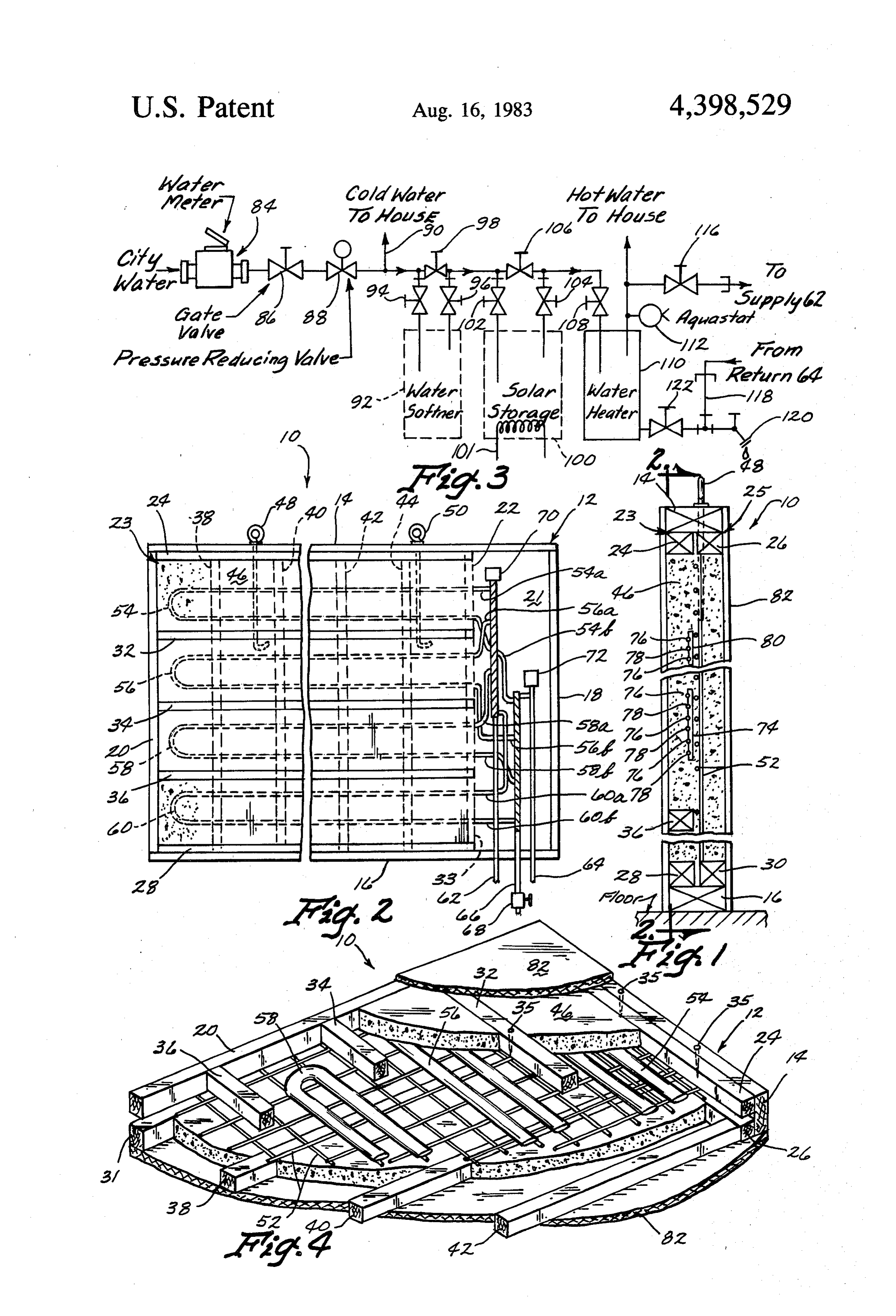
structure employing a slab floor. Further, because the concrete floor serves as a thermal reservoir to facilitate BRIEF DESCRIPTION OF THE DRAWINGS thermal conduction and radiation to the surrounding air, the surface area of the floor exposed to and in 15 FIG. 1 is a shortened sectional view of the solar heat contact with the surrounding air is an important factor ing wall.
in determining the rate of heat transfer. A heating sys FIG. 2 is a shortened sectional view of the solar heat tem which provides more surface area of the thermal ing wall taken along line 2-2 of FIG.1. reservoir in contact with the air within the building to FIG. 3 is a schematic of the plumbing system con be heated than is afforded in floor heating systems, is 20 nected to the solar heating wall. thus desirable. Furthermore, prior solar water circulat ingFIG. 4 is a partial perspective view of the wall show portions broken away.
ing heating systems have used a piping system separate from the potable water system of the building, thus DESCRIPTION OF THE PREFERRED increasing the cost of the solar system. EMBODIMENT
Accordingly, it is an object of the present invention 25 to provide an improved water circulating solar heating The numeral 10 generally refers to a solar heating system for a commercial or residential structure. wall of this invention. The basic structure of wall 10 is It is a further object of the present invention to pro two rectangular frames 23, 25 which are formed of vide a water circulating solar heating system which conventional 2X2 stock. Frame 23 is formed by a side maximizes surface area in contact with the living space 30 member 20, a top horizontal member 24, a bottom hori within a structure. Zontal member 28, and three interior horizontal mem It is a further object of the present invention to pro bers 32, 34,36. There is no vertical member at the right vide a water circulating solar heating system which is hand side as viewed in FIG. 2 of frame 23. Immediately adapted to use potable water supplied through city below frame 23 is a mesh reinforcing wire 52 which water systems. 35 rests on top of frame 25.
It is a further object of the present invention to utilize Frame 25 is comprised of an upper horizontal men the walls of a residential or commercial structure as the ber 26, a lower horizontal member 30, outer vertical thermal reservoir in a circulating, solar water heating side members 31, 33, and interior vertical members, 38, system. 40, 42, and 44. Thus frame 23 includes horizontal mem It is a further object of the present invention to pro bers 24, 28, 32, 34, 36 whereas in contrast frame 25 vide a frame for a concrete wall which is economical includes only vertical members 38, 40, 42, 44. Horizon and affords good support. tal members 24, 2834, 36 of frame 23 are secured in It is a further object of the present invention to pro place by nails 35 which extend downwardly into the vide a solar wall structure which can be easily con frame 25 below so as to secure frames 23, 25 together. structed by personnel at the building site. 45 An outer rectangular wall frame 12 is formed by It is a further object of the present invention to pro securing an upper plate 14 and a lower plate 16 in cover vide a solar wall structure which is economical in manu ing relation over the top members 24, 26 and the bottom facture, efficient in use, and strong in construction. members 28, 30 of interior frames 23, 25. Plates 14, 16
Summary of the invention
are preferably of twice the thickness of frames 23, 25.
50 Furthermore, plates 14, 16 protrude beyond the right
A water circulating, solar heating system is shown on hand edge (as viewed in FIG. 2) of frames 23, 25. Plates the drawings and utilizes a solar heating wall. The wall 14, 16 are interconnected by a stud 18 to form a rectan frame includes on one side a four member rectangular gular cavity 21.
main frame with horizontally disposed, evenly spaced Interior frames 23, 25 are filled between vertical sup cross supports along one face of the main frame. On the 55 port member 22 and vertical member 20 with a material other face of the frame are vertically disposed, evenly 46 which can be packed therein and is substantially solid spaced cross supports. or will form into a substantially solid mass. Preferably A series of separate water circulation tubes formed this packing material 46 is concrete. Extending through into single loops lies in single vertical plane in the frame. frame member 14 are two lift lugs 48 and 50 which lie in Each separate tube extends from a supply pipe (which is a vertical plane in the approximate center of wall 10. connected to the water source of the structure) to a rial Lugs 48 and 50 extend into and are set in packing mate return pipe (which is connected to the drain of the 46.
structure's water system). The separate loops are hori A series of separated water circulation tubes 54, 56, Zontally disposed and extend substantially along the 58 and 60 are formed into individual loops. Each tube entire length of the wall. The supply and return pipes 65 rests on top of mesh wire 52 (as viewed in FIG. 2) and for the separate circulation tubes are located adjacent extends horizontally from the cavity 21 into one of the one another in a cavity formed at one end of the wall's horizontal spaces formed between horizontal members frame. v. 32, 34, 36 of frame 23. The water circulation tubes are 4 all disposed in the same vertical plane adjacent and coming from the city water supply. Thus, the potable parallel to the reinforcing wire mesh 52. water is preheated while in the storage unit. One end of each separated water circulation tube, i.e., After solar storage unit 100, another inlet valve 108 the intake end identified as 54a, 56a, 58a and 60a, re joins the plumbing to water heater 110. An aquastat 112 spectively, is connected to a water supply pipe 62 as is connected to the water heater outlet pipe 114. Pipe shown in FIG. 2. Similarly, the return end of each 114 leads to the various hot water taps in the structure, water circulation tube, i.e., 54b, 56b, 58b and 60b, re as well as to supply 62 by way of valve 116. Pipe 118 spectively, is connected to the same system return pipe connects to return 64 and leads to drain 120. Drain 64 by way of drain pipe 66. Drain valve 68 on drain pipe valve 122 leads from the base of the water heater to 66 and air vents 70 and 72 atop supply pipe 62 and O drain 120. Thus, the present system utilizes the struc return pipe 64, respectively, complete the water circula ture's potable water supply and supplements the struc tion piping within main frame 12. ture's water heating system.
The tubes used are currently commercially available The cold water line may be placed before or after the under the trade designation SolaRoll, and are sold by pressure reducing valve 88. Similarly, the relative posi Bio-Energy Systems, Inc. of Ellenville, N.Y. Each tube 15 tions of the other valves may be varied so long as the includes a plurality of tubes (usually 6) which are joined water heater and the solar storage tank are located after together by flexible plastic. FIG. 1 illustrates how these pressure reducing valve 88.
tubes appear in section, but FIGS. 2 and 4 illustrate the In operation, valve 116 is simply opened to allow tubes schematically rather than in full size. water heated by water heater 110 and solar storage unit The cross sectional view shown in FIG. 1 is a true 20 100 to enter supply 62, thus filling circulation tubes 54, representation of the preferred embodiment. In particu 56, 58 and 60. Primarily by conduction, heat will be lar, circulating tube set 74 includes a cross-sectional transferred from the hot water within the circulation view of three identical supply tubes 76 and three identi tube to packing material 46. By conduction and radia cal return tubes 78 placed in the preferred compacted tion, the thermal energy within packing material 46 will position. Similarly, FIG. 1 shows a cross sectional, 25 be transferred into the air in contact with the exterior partial view of a second tube set 80 wherein two supply and interior surfaces of wall 10. The relatively large tubes 76 and one return tube 78 are shown. A suitable volume of the packing material 46 as compared to the covering material 82 (FIG. 4), such as sheet rock or volume of the water circulating through the various masonite, can be utilized to finish the exterior and inte circulating tubes, allows for the storage of much more rior surfaces of wall 10. 30 thermal energy than can be obtained within the circulat The construction of wall 10 is simple and can be done ing water at any given time. The packing material 46 by a carpenter during the construction of a house. The will radiate and conduct heat into the surrounding air at entire wood frame and wire mesh are built and assem a rate depending on the thermal conductivity of the bled on the floor. Next concrete is poured through the packing material 46 and the covering material 82, the wire mesh 52 until frame 25 is completely filled to the 35 movement of the surrounding air and the humidity in level of wire mesh 52. Then tubes 54, 56,58, 60 are laid the surrounding air, as is well known. The number of in place between the horizontal members 32, 34, 36 of solar walls utilized in a particular structure is, of course, frame 23. The tubes 54, 56,58, 60 are preferably pressur discretionary with the owner, however, it is clear that a ized prior to being covered with concrete. Concrete is much larger surface area containing circulating water then poured within interior frame 23 so as to completely 40 tubes can be placed in contact with the air within a cover tubes 54, 56, 58, 60. The wall may be lifted to a given structure by utilizing several solar walls as op vertical position by means of hooks 48, 50 and sheet posed to the use of a solar, circulating water, concrete rock 82 sheets can then be attached to both faces of the floor slab.
wall. Placement of cross supports 32, 34, and 36 perpendic FIG. 3 is a schematic of the plumbing located on the 45 ular to oppositely disposed cross supports 38, 40, 42, exterior of main frame 12 which connects to supply 62 and 50 provide support for the packing material 46 and return 64. From left to right in FIG. 3, water from when the wall 10 is flexed along either its height or its a supply such as city water (which would pass through width. If flexed along either direction, one or the other a water meter 84) leads to gate valve 86. A pressure sets of cross supports serves to assist main frame mem reducing valve 88 which reduces the water pressure 50 bers and cross beams of main frame 12 and reinforcing (which is typically 60 psi) to 30 psi is the next item in the mesh 52.
plumbing system. A cold water supply 90 is then con It is obvious that the dimensions and materials uti ventionally connected to the various cold water taps. lized in the construction of solar wall 10 can vary Water softener 92 is placed in the system and it in greatly. Copper tubing is preferred for supply pipe 62 cludes an intake valve 94 and outlet valve 96 as well as 55 and return pipe 64, but various materials will suffice. a bypass valve 98. Water softener 92 is followed by a Similarly, the number and shape of the various circulat solar storage unit 100 which receives water from inlet ing tubes is not crucial, but clearly it is preferable to valve 102. Outlet valve 104 permits water to be drawn have the largest possible surface area of circulating out of storage unit 100. Bypass valve 106 is positioned tubes in contact with the packing material 46 per unit between valves 102, 104. volume of water circulated therethrough. Further, Solar storage unit 100 includes a heat exchanger coil good thermal contact between the circulating tubes and 101 in the bottom thereof, and coil 101 is connected to the packing material is preferable. Other packing mate a solar collector (not shown) which collects heat from rial and materials for the frame of wall 10 can be utilized the sun. Coil 101 and the solar collector are connected with the only limitation being cost. If circulating tubes in a closed fluid system which uses glycol or other 65 of sufficient strength are utilized, it is possible for the suitable fluid to carry the heat from the solar collector pressure reducing valve to be deleted and a city water to heat exchanger 101. Exchanger 101 transfers heat to supply can then be directly fed to the solar plumbing the water in storage unit 100 which is potable water system. Further, the solar walls can be used in conjunc 5 tion with a circulating water, concrete floor slab, but one end to said vertical said member and extending additional support for the floor will then be needed. horizontally across said second rectangular frame. Many other variations within the scope of the claims 5. A water heating system comprising: will be obvious to those skilled in the art. a vertical wall formed at least partially from con It is clear from the above description that all of the crete;
above stated objectives are met by the present inven a water tube partially embedded within said concrete tion. wall and having an inlet end and an outlet end What is claimed is: extending outside said concrete wall; 1. A water heatable wall for a structure comprising: a water inlet pipe adapted to be connected to a source a first rectangular frame having a first upper horizon 10 of potable water;
tal frame member, a first lower horizontal frame a solar storage unit adapted to store heat received member, and a plurality of parallel vertical studs from a solar collection system; extending between said first upper and first lower a heat exchanger within said solar storage unit an frame members; connected to said inlet pipe so as to permit the a second rectangular frame having at least one verti 15 water from said inlet pipe to be heated by the heat cal side frame member and a plurality of horizontal within said solar storage unit; spaced apart parallel frame members extending a water heater connected to said heat exchanger so as across the width of said second rectangular frame; to receive preheated water from said heat ex said first and second rectangular frames having the changer and to further heat said water to a prede same size and being attached to one another in 20 termined temperature, said heater having a water superimposed relationship to form a wall frame outlet connection and a water return connection; having a thickness which comprises the combined means connecting said water outlet connection to thickness of said first and second frames; said inlet end of said water tube, and further con at least one elongated flexible water tube positioned necting said outlet end of said water tube to said in at least one of the spaces between said spaced 25 return connection of said water heater.
apart horizontal frame members of said second 6. A method for constructing a water heatable wall frame, said tube having an inlet end and an outlet comprising:
end extending beyond the outer rectangular edges of said second rectangular frame; forming a first rectangular frame having a first hori concrete filling the open areas within said wall frame 30 zontal upper frame member, a first horizontal bot so as to form a concrete wall having a thickness tom frame member, and a plurality of first vertical and shape of said wall frame; and frame members in spaced apart parallel relation; said water tubes, said vertical studs of said first frame, forming a second rectangular frame having at least and said horizontal members of said second frame one vertical side frame member and a plurality of being embedded within said concrete. 35 horizontal frame members in spaced apart parallel 2. A water heatable wall according to claim 1 relation to one another; . wherein an upper plate and a lower plate are attached to positioning said first frame in registered allignment the upper and lower edges of said wall frame, said plates over said second frame and securing the two to extending beyond one of the side edges of said wall gether;
frame, a vertical wall stud spaced from said one side 40 placing at least one flexible water tube within at least edge of said wall frame and interconnecting said upper one of the horizontal spaces between said horizon and lower plates so as to form a wall cavity adjacent tal members of said second frame; with the oppo said one side edge of said wall frame, said inlet and site ends of said water tube extending outwardly outlet ends of said water tube extending into said wall beyond the outer edges of said first and second cavity. 45 frames;
3. A water heatable wall according to claim 2 pouring concrete into the open spaces within said wherein a sheet of wire mesh material is positioned super-imposed registered first and second frames between said first and second frames and is embedded whereby said water tube, said first vertical frame within said concrete. members of said first frame, and said parallel hori 4. A water heatable wall according to claim 1 50 zontal members of said second frame will be em wherein said second rectangular frame comprises only bedded within said concrete, the opposite ends of one vertical said frame member, said horizontal frame said water tube extending outside said concrete. members of said second frame each being connected at w
Provenance
- Collection
- Patents citing this work
- Pages
- 5
- Method
- pdftotext (the PDF's own text layer) + pdftoppm 300dpi page scans
- Patent office record
- patents.google.com →
- Source
- Google Patents citing-documents table
- Assignee
- Schoenfelder James L
- Published
- 1983-08-16
- Transcribed from
- patentimages.storage.googleapis.com →