

patent · US4405299A
Burner ignition and flame monitoring system
20 September 1983
Text
Page 1scan →
United States Patent (19)
Serber
54 burner ignition and flame
Monitorng system
75 Inventor: Stephen L. Serber, New Hope, Minn.
(73) Assignee: Honeywell Inc., Minneapolis, Minn.
52 U.S. C. ......................................... 431/78; 431/25 58) Field of Search ........................ 431/25, 59, 74,78
3,385,648 5/1968 Quinn .................................... 431/59
4,298,335 11/1981 Riordan et al........................ 431/25 Primary Examiner-Carroll B. Dority, Jr.
Attorney, Agent, or Firm-Alfred N. Feldman
A fuel burner ignition system using a hot surface ignitor means as both an ignition element and as one element of a flame rectification sensor. The hot surface ignitor means ignites fuel issuing from a fuel burner, and also acts as the flame rod or sensing means of a flame detect ing System.
10 Claims, 2 Drawing Figures
Drawings
Page 2drawing sheetscan →
Page 3scan →
drawbacks in that a separate flame detection device is
BURNER IGNITION AND FLAME MONITORING required in addition to the ignitor itself. SYSTEM DESCRIPTION OF THE PRESENT INVENTION
CROSS-REFERENCE TO OTHER 5 The present invention is directed to a hot surface APPLICATIONS: ignitor type of system in which the hot surface ignitor The present invention has subject matter which re has a dual function. The hot surface ignitor is first used lates to the same technology as a pending application as an ignitor element, and then is deemergized. It is also Ser. No. 282,566 filed in the names of J. E. Bohan and B. placed inmeans a flame detection circuit as the flame rod or J. Hinton on July 13, 1981 entitled Interrupted Power 10 sensing mode of of a flame rectification system. In this operation, the ignitor is not only energized to
Hot Wire Gas Ignition Control System which is as signed to the assignee of the present invention. create the pilot flame, but is also used as a sensing or flame rod element in the detection system. This allows
BACKGROUND OF THE INVENTION for the simplification of the system wherein the same In recent years, due to the accelerating cost of fuels, 15 hot surface ignitor provides the function of igniting the it has become desirable to replace the conventional fuel, and the function of becoming part of the flame standing pilot used in gas furnaces with an interrupted rectification system to sense the existence of the flame at type of ignition system. In the past the standing pilot has the burner.
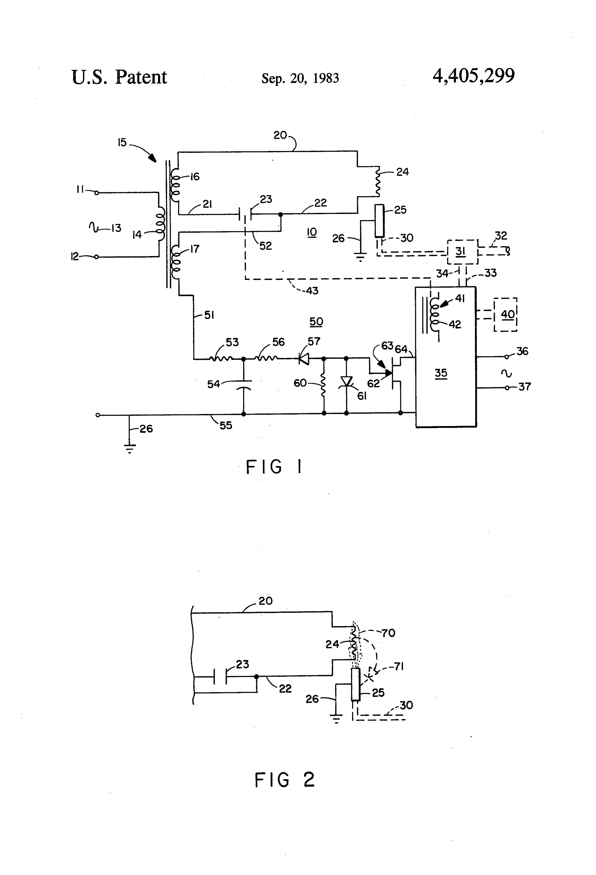
been the primary ignition source for gas furnaces. The 20 BRIEF DESCRIPTION OF THE DRAWINGS standing pilot was very reliable and was very inexpen sive to manufacture. In the days when gaseous fuels FIG. 1 is a schematic diagram of a complete burner were relatively cheap, the continuously ignited standing ignition and flame monitoring system, and; pilot used an insignificant amount of fuel, from a cost FIG. 2 is a representation of the flame rectification standpoint. In recent years the shortage of fuels and the 25 function when a flame exists.
acceleration of their cost has made the standing pilot DESCRIPTION OF THE PREFERRED undesirable in certain types of applications. In addition, EMBODIMENT a number of states have legislated that installation of fuel burning equipment can no longer include a standing A complete burner ignition and flame monitoring pilot in order to conserve fuels. This change in the 30 system is generally disclosed at 10. This system is ener status of the standing pilot has dictated that the standing gized at a pair of terminals 11 and 12 by an alternating pilot be replaced with some other type of ignition current indicated at 13 which supplies power to a pri SOCC. mary winding 14 of a transformer generally disclosed at The most common ignition source to replace the 15. The transformer 15 has two secondary windings 16 standing pilot has been a spark ignition source that and 17. The secondary winding 16 forms a first power typically uses a silicon controlled rectifier as the heart 35 source means for the system. The power source means of a relaxation oscillator for the generation of an igni 16 is connected by conductors 20, 21, and 22 in a series tion spark. While this type of equipment is generally circuit including an ignition control switch 23 and a hot reliable, and only moderately more expensive than surface ignitor means 24. The hot surface ignitor means other approaches, it has the drawback of generating 24 can be any type of hot surface ignitor such as a Ni both audible and radio frequency noises. The constant 40 chrome wire or a ceramic resistor having a negative arcing of a spark for generation of a flame at the pilot is temperature objectionable. At the same time this arcing causes the face ignitors coefficient. Both of these types of hot sur generation of radio frequency noises that are transmit It will be noted that when theinignitor are well known the electric ignition art.
control switch 23 ted in the normal power lines of a home and cause inter is closed that a series circuit is created from the first ference with other types of electrical equipment. For power source means 16 via the conductors these reasons, the spark ignition systems that are replac 22 to include the hot surface ignitor means20,24. 21, and ing the standing pilot systems have deficiencies which allows the hot surface ignitor means to be energizedThis and make them of limited value.
An attempt has been made to provide other types of when properly energized will heat to a fuel ignition ignition systems for burners to replace the spark type of 50 temperature
The hot for the system.
surface ignitor means 24 is placed adjacent a ignition systems. The most common replacement for the fuel burner 25 which spark ignition system is a hot surface ignition system 25 typically would beisthe grounded at 26. The fuel burner pilot burner of a gas furnace wherein an ignition element made of a high resistance and the fuel would typically be natural or liquid petro metal or of a high resistance ceramic is used. The high 55 leum vaporized gas. The present invention is not limited resistance element is energized from a source of poten tial and will glow or be raised to an ignition temperature to this type of a fuel burner structure, but is most typi cally applicable to this type of structure. The fuel for the fuel being used. The drawback of this type of a burner 25 would be connected by pipe 30 to a valve 31 system is that the hot surface ignitors have a relatively short life when used as an ignition element if kept con of fuel turn that in is connected to piping 32 that is the source to the burner 25. The valve 31 is connected by stantly energized. As such, it has become necessary to provide a short energizing period for the hot surface conductors 33 and 34 to a primary control means gener ignitor, and then a means separate therefrom to monitor ally disclosed at 35. The primary control means 35 is the existence of a flame, once one has been established. energized at terminals 36 and 37 from a convenient source of alternating current potential and in turn is
In the earlier cross-referenced application, which is 65 controlled assigned to the assignee of the present application, a by a condition responsive means 40. The system for energizing a hot surface ignitor and then condition responsive means 40 typically would be a monitoring the flame by a separate flame detection thermostat in a residential gas furnace installation. The arrangement is disclosed. This arrangement has certain primary control means 35 includes within it a switch 4 control means generally disclosed at 41. The switch At this same time the flame sensing circuit means 50 control means 41 includes a relay 42 which is mechani obtains a rectified signal across the flame 70 by means of cally linked at 43 to the ignitor control switch 23. the phantom diode 71. This rectified potential causes The burner ignition and flame monitoring system 10 the field effect transistor 63 to change its state and the is completed by a flame sensing circuit means 50 that is 5 primary control means 35 causes the relay 42 to open powered by way of a conductor 51 connected to an circuit the contact or ignition control switch 23. This alternating current power source means or secondary deenergizes the hot surface ignitor 24 so that it acts as a winding 17 of the transformer 15. The alternating cur flame rod rather than as an ignition element. The re rent power source means 17 is connected by a conduc moval of energizing power to the hot surface ignitor 24 tor 52 to the conductor .22 that is common with the 10 allows it to have an extended life over an ignitor which ignitor control switch 23. The conductor 51, which was constantly energized at an ignition temperature. Supplies power from the alternating current power The present invention has been disclosed in an ele source means 17 to the flame sensing circuit means 50, mentary form wherein the hot surface ignitor 24 is used supplies an alternating current potential to a resistor 53 both as an ignition element and as part of a flame rectifi that is coupled to ground by a capacitor 54. The ground. 15 cation sensor with the burner 25. A simple solid state is at the conductor 55 and is a common ground to the primary control and flame sensing circuit means has ground 26 of the burner 25. The flame sensing circuit been disclosed. This circuit means could be altered means 50 further has a resistor 56 that is connected extensively without varying from the scope of the pres through a diode 57 to a further resistor 60. The output ent invention. The present invention is defined solely by of the voltage across the resistor 60 is clipped by a zener the scope of the appended claims. diode 61 that is connected to a gate 62 of a field effect The embodiments of the invention in which an exclu transistor that is generally disclosed at 63. The source sive property or right is claimed are defined as follows: drain connections of the field effect transistor 63 are 1. A burner ignition and flame monitoring system connected between the ground 55 and an input point 64 adapted to control a fuel burner in response to a condi to the primary control means 35. The flame sensing 25 tion responsive means, including: hot surface ignitor circuit means 50 is a solid state flame rectification type means adapted to be mounted in proximity to said fuel of flame sensing circuit means. burner to ignite fuel issuing from said fuel burner; first The function of a flame rectification type of sensor is power source means connected to said hot surface igni well known in the art. When a flame exists with an tor means in series circuit with an ignitor control switch alternating current potential impressed across it, the to controllably energize said ignitor means to generate flame acts to conduct more current in one direction if an ignition temperature at said ignitor means; flame the polarity of the alternating current than in the re sensing circuit means adapted to be connected to and verse polarity. As such, the flame creates the equivalent operatively energized from alternating current power of a rectifier and this equivalence is used to sense the Source means concurrently with the energization of said presence or absence of a flame. Flame rectification type 35 hot surface igniter means; said ignitor means being con amplifiers are well known and the present embodiment nected to said flame sensing circuit means with said merely is an example of one arrangement that would flame sensing circuit means being responsive to the accomplish the use of a flame rectification signal from presence or absence of flame between said ignitor the combined hot surface ignitior means 24 and the means and said burner by said flame effectively rectify burner 25. The control signal between the point 64 and ing said alternating current power source means; pri ground is supplied to the primary control means 35 mary control means connected to said flame sensing which can be any type of solid state primary control. A circuit means and being responsive to the presence or number of such controls are currently marketed and absence of said flame at said burner; and switch control they respond to a flame rectification signal. They oper means operated by said primary control means to in ate a relay in response to the flame and a condition 45 turn operate said ignitor control switch to deenergize sensing means to in turn control a source of fuel. said hot surface igniter means when flame is sensed. In FIG. 2 the flame rectification function of the pres 2. A burner ignition and flame monitoring system as ent device is pictorially displayed. In FIG. 2 a flame 70 disclosed in claim 1 wherein said first and said alternat is disclosed as existing between the hot surface ignitor ing current power source means include two secondary means 24 and the grounded burner 25. When a potential 50 windings of transformer means adapted to be connected is supplied across the conductor 22 and ground 26 of an to a source of alternating current potential. alternating current type, a rectified current flows as is 3. A burner ignition and flame monitoring system as indicated by the phantom diode 71. disclosed in claim 2 wherein said ignitor control switch The disclosure of the present invention has been pro is a relay contact; and said switch control means in vided in a very elementary form wherein a simple flame 55 cludes a relay which operates said relay contact. rectification sensing circuit means 50 has been disclosed 4. A burner ignition and flame monitoring system as as controlling a primary control means 35 which re disclosed in claim 3 wherein said flame sensing circuit sponds to the condition control means or thermostat 40 means is a flame rectification type of flame sensing to control gas to a gas valve 31 which in turn supplies circuit.
gas to the burner 25 and the hot surface ignitor 24. 60 5. A burner ignition and flame monitoring system as When the condition control means 40 calls for the oper disclosed in claim 4 wherein said hot surface ignitor ation of the burner 25, the valve 31 is opened by the means is a resistor.
primary control means 35. Gas issues from the burner 6. A burner ignition and flame monitoring system as 25. At this same time the relay 42 is energized thereby disclosed in claim 5 wherein said resistor is a negative closing the contact 23 to supply a power source 16 to 65 temperature coefficient resistor. . . . the hot surface ignitor 24. The hot surface ignitor raises 7. A burner ignition and flame monitoring system as in temperature until an ignition point has been reached disclosed in claim 6 wherein said fuel issuing from said and the fuel issuing from the burner means 25 is ignited. fuel burner is a gaseous fuel.
Page 5scan →
8. A burner ignition and flame monitoring system as is a relay contact; and said switch control means in disclosed in claim 2 wherein said flame rectification cludes a relay which operates said relay contact. type of flame sensing circuit and said primary control 10. A burner ignition and flame monitoring system as disclosed in claim 9 wherein said flame sensing circuit means are solid state electronic circuit means. 5 means is a flame rectification type of flame sensing 9. A burner ignition and flame monitoring system as circuit.
disclosed in claim 8 wherein said ignitor control switch
Provenance
- Collection
- Patents citing this work
- Pages
- 5
- Method
- pdftotext (the PDF's own text layer) + pdftoppm 300dpi page scans
- Patent office record
- patents.google.com →
- Source
- Google Patents citing-documents table
- Assignee
- Honeywell Inc.
- Published
- 1983-09-20
- Transcribed from
- patentimages.storage.googleapis.com →