

patent · US4411490A
Apparatus for collecting, distributing and utilizing solar radiation
25 October 1983
Text
Page 1scan →
1 ? 2 ea 83. a 4 rc
United States Patent (19)
Daniel
(54) apparatus for collecting,
Distributing and utilizng solar
Radation
(76 Inventor: Maurice Daniel, 1733 19th St., N.W., Washington, D.C. 20009 (51) Int. C. ............ es ess 4 as s so a a G02B 5/14 (52) U.S. Cl. ............ asa eo a - ---a 350/96.10; 350/96.18;
(58) Field of Search a a wa w a 350/96. 10, 96.15, 96.16,
3,314,331 4/1967 Wiley ...................................... 88/24
4,198,953 4/1980 Power ............................. 350/258 X 4,292,959 10/1981 Coburn, Jr. ..................... 350/262 X 4,297,000 10/1981 Fries ......... ... 350/96.24 4,302,069 11/1981 Niemi ............................... 350/96.15
Foreign patent documents
55-53310 4/1980 Japan ................................ 350/96.18
Other publications
Nasa Tech Briefs, vol. 3, No. 2, Summer 1978, Edwards, "Optics for Natural Lighting," pp. 209-211.
Primary Examiner-John D. Lee
Assistant Examiner-Frank Gonzalez
Attorney, Agent, ur Firm-Sixbey, Friedman & Leedom
The apparatus for collecting, distributing and utilizing solar radiation includes a solar collection panel (24) having an array of solar gathering cells (1,37) which provide radiation to a light collecting unit (3, 4, 39). This light collecting unit (3, 4,39) provides radiation as a single beam to a lens system (5, 7) which provides a coherent beam to a lightpipe (8). This beam is then directed to use units such as a light to electricity con verter (100, 154), heat distributing elements (202, 213, 230, 244, 270) and light distributing elements (322,336,
20 Claims, 21 Drawing Figures
Drawings
Page 2drawing sheetscan →
Page 3drawing sheetscan →
Page 4drawing sheetscan →
Page 5drawing sheetscan →
Page 6drawing sheetscan →
Page 7drawing sheetscan →
Page 8drawing sheetscan →
Page 9scan →
developing a truly efficient solar collection and utiliza
APPARATUS FOR COLLECTING, DISTRIBUTING tion system. Generally speaking, an optical fiber is a AND UTILIZNG SOLAR RADATION long thin flexible coated rod or core of transparent material such as glass or plastic surrounded by a second
DESCRIPTION transparent material or cladding. The cladding material l. Technical Field has a lower index of refraction than the core material. The present invention relates to means for collecting Light travelling down the length of the core at shallow and utilizing solar energy and more particularly to angles with respect to the longitudinal axis of the core is means for collecting solar energy at a remote location O internally reflected at the core-cladding interface to and transmitting the energy so collected to a variety of effectively "trap' the light within the core material utilization devices. unit the light reaches the end of the optical fiber. It can 2. Background Art therefore be seen that optical fibers offer a convenient Recent interest in establishing public and private means for conducting sunlight from one point to an alternatives to the conventional use of fossil and nuclear other.
fuels for providing heat and power has focused exten 15 The optical solar energy converter disclosed in U.S. sively on the exploitation of solar radiation as a source Pat. No. 3,379,394, issued to Bialy on Apr. 23, 1968, of relatively inexpensive, renewable and non-polluting provides an early example of the use of optical fibers to energy. This interest in turn has led to new advances in receive and transmit solar radiation from a solar collec the art of collecting and utilizing solar radiation. Devel tion site to a thermoelectric unit. Additional examples - opment in the field of solar cell technology, for exam 20 of solar collectors with optical fiber networks can be ple, has made possible the realization of ever greater found in U.S. Pat. No. 3,780,722, issued to Swet on Dec. efficiencies in converting sunlight directly into electric 25, 1973; U.S. Pat. No. 4,026,267, issued to Coleman on ity. Numerous improvements have also been introduced May 31, 1977; and U.S. Pat. No. 4,174,978, issued to into systems such as those employing solar heat ex Lidorenko et all on Nov. 20, 1979. In spite of the many changers and solar boilers for extracting and applying 25 advantages to be gained from employing optical fibers the heat of solar radiation.
Notwithstanding the progress heretofore achieved, to gather and distribute solar radiation, however, the principal economies of size and cost available through most solar devices continue to suffer from several com mon yet serious limitations attributable to the fact that type notedfiber the use of optics are not realized in systems of the above. Specifically, all of the aforemen utilization of solar energy generally takes the form of in 30 tioned optical fiber solar situ utilization. The collection of solar radiation is gen separate optical fibers ordistribution optical systems rely upon bundles to distribute erally undertaken at an outdoor location, and most solar incident sunlight from each focal point or receiving devices are designed to perform their conversion or location on a solar collecting surface. A conventional heat transfer functions at the solar collection site. Thus, most solar devices are exposed to the deleterious effects 35 solar collecting panel having a large array of solar re ceiving devices, such as illustrated in FIG. of the of the elements. A particularly serious problem is cre previously cited Coleman reference, consequently re ated when sensitive and fragile solar cells are subjected quires a correspondingly large number of optical fibers to such exposure. The corrosive action of the weather or fiber bundles to conduct light from the collecting significantly interferes with the operation of solar cell arrays, and the consequent maintenance and replace 40 surface to the ultimate solar utilization device. The ment costs appreciably add to the overall expense of a attendant bulk, complexity and expense of transmitting solar cell conversion system. Additional problems arise devices having large numbers of fibers or optical bun when solar heat exchangers or solar boilers are in dles may, of course, prove prohibitive in many situa volved. If the heat exchanger or boiler is designed to tions, and it would be of obvious benefit to provide a furnish heat to a residential unit, the solar collector is 45 means for distributing solar radiation through a rela often mounted on the roof of the unit and the require tively small number of optical fiber bundles each having ment of close physical proximity between the collector a relatively small cross-sectional area. To this end, it is and the heat exchanger or boiler necessitates costly necessary to provide a means for concentrating solar reinforcement of the structural members of the roof in radiation received at a solar collection site prior to order to support the weight of the entire collection and SO transmitting the radiation to the utilization site. heat exchange system. Alternately, when the solar col Apart from systems designed to receive and distrib lector is located on the ground away from the residen ute solar radiation, much recent attention has been de tial unit to be heated, complicated piping and valve voted to the development and construction of practical mechanisms are needed to transport the heat exchange devices for utilizing solar energy. Solar battery-type medium from the collection site to heat radiators inside arrangements which convert sunlight directly into elec the unit. The expense of the entire collection and heat tricity are known, as evidenced by U.S. Pat. No. transfer system is again increased, while the process of 4,153,475, issued to Hider et all on May 8, 1979. Al transporting the heat exchange medium and the accorn though of obvious utility, arrangements of the type panying heat loss can lead to further costly inefficien disclosed in Hider et al are principally intended to func cies. In view of these disadvantages, a means for collect 60 tion through direct interaction with incide.ht sunlight. ing and transmitting solar energy from an optimum No provision has been made for adapting prior art solar collection location to a solar utilization device posi batteries or other solar utilization devices to receive tioned in a separate but optimum utilization location solar radiation indirectly from optical fiber distribution would greatly enhance the operational efficiency, finan systems arranged to transmit light from an optimum cial attractiveness and flexibility of a solar conversion 65 solar collection site to an optimum utilization site. On system. the other hand, light utilization devices which have The rapidly-growing field of fiber optics furnishes been constructed for use with prior art optical fiber perhaps the most promising solution to the problem of transmission systems, such as the light guide disclosed 10 in U.S. Pat. No. 4,017,150, issued to Imai on Apr. 12, incident solar radiation through optical windows into a 1977, or the terminal lens sets disclosed in the Edmund light gathering chamber. The light gathering chamber Scientific Co. catalog, page 59 (Spring/Summer 1979), in turn employs a plurality of conical mirrors to redirect have not been adapted to interface with solar radiation the solar radiation toward an optical entrance window, distribution systems. It is thus apparent that solar utili whereupon a light trap captures and removes the solar zation structures compatable with relatively simple, radiation from the light collection chamber. Light trav efficient and inexpensive solar collection and distribu eling through the light trap escapes via exit windows tion systems would prove of great value in a wide vari formed at the end of the light trap opposite the entrance ety of both industrial and residential settings. window and is subsequently focused by a lens system
DISCLOSURE OF THE INVENTION into a lightpipe for distribution to a remote utilization It is therefore a primary object of the present inven site.One type of utilization device takes the form of a tion to provide a practical means for gathering solar radiation at an optimum collection site and distributing light-to-electricity converter, wherein solar radiation radiation so gathered to an optimum utilization site. 15 received from a solar collection panel positioned at a It is additional object of the present invention to remote solar collection site is transmitted through a provide a means for gathering solar radiation at an light-emitting fabric overlying a plurality of solar cells. optimum collection site and concentrating the radiation The solar cells generate usable electricity from the solar so gathered to enable high intensity transmission of the radiation leaving the light-emitting fabric, which elec solar radiation through a relatively small number of 20 tricity may be removed from the light-to-electricity optical fiber bundles to a solar utilization device located converter and employed in conventional electric de at an optimum utilization site. vices. An alternative form of the light-to-electricity It is another object of the present invention to pro converter utilizes an optical tree-type structure in lieu vide a solar collection panel including at least one radia of a light-emitting fabric to distribute light received tion gathering cell for gathering solar radiation and a 25 from the solar collection panel to solar cells mounted light collection chamber in combination with a light within the converter. The optical tree structure includes trap for redirecting and removing the gathered solar a trunk portion with a plurality of branch portions radi radiation from the solar collection panel. ating therefrom.
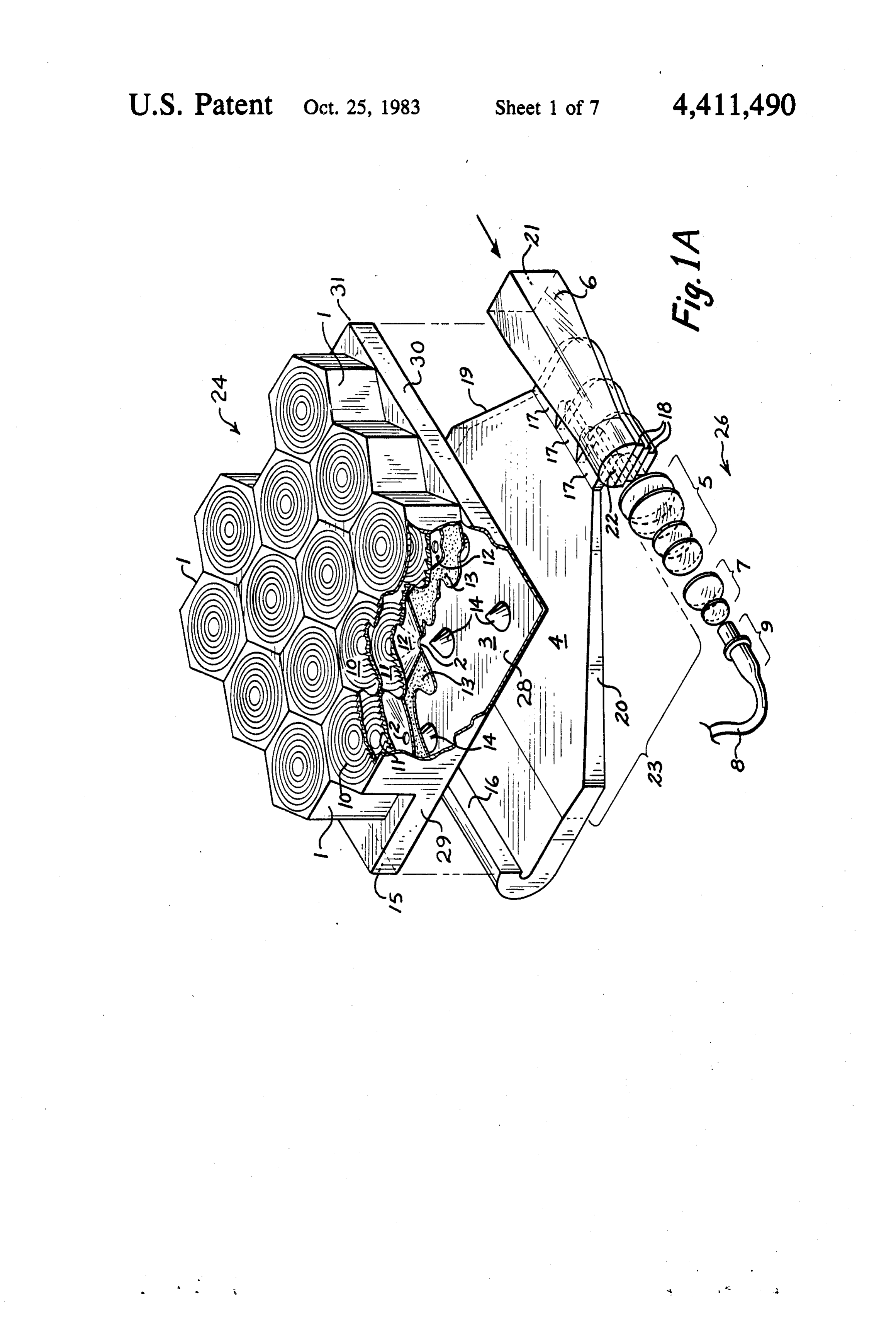
It is another object of the present invention to pro Additional solar utilization devices in the form of a vide a solar collection panel wherein the panel includes 30 solar welder which focuses infrared radiation to furnish a radiation gathering cell for gathering incident solar a point source of heat suitable for welding operations, radiation and a light collection chamber in combination heat distributing devices for uniformly distributing in with reflecting elements and a light trap for redirecting frared radiation as a general source of heat, and illumi and removing the solar radiation so gathered to a re nating devices for distributing visible radiation as a mote utilization site with a minimum of optical loss. 35 source of usable illumination are also disclosed. It is another object of the present invention to pro vide a variety of solar utilization devices for use in BRIEF DESCRIPTION OF THE DRAWINGS connection with a solar collection panel which gathers The various features, objects and advantages of the solar radiation at an optimum collection site and distrib present invention will become more apparent from the utes the radiation so gathered to the utilization devices. 40 following Brief Description of the Drawings, wherein It is still another object of the present invention to FIG. 1A is a perspective view of a solar collection provide a light-to-electricity converter which receives panel constructed in accordance with the present inven solar radiation from a remote solar collection site and tion;
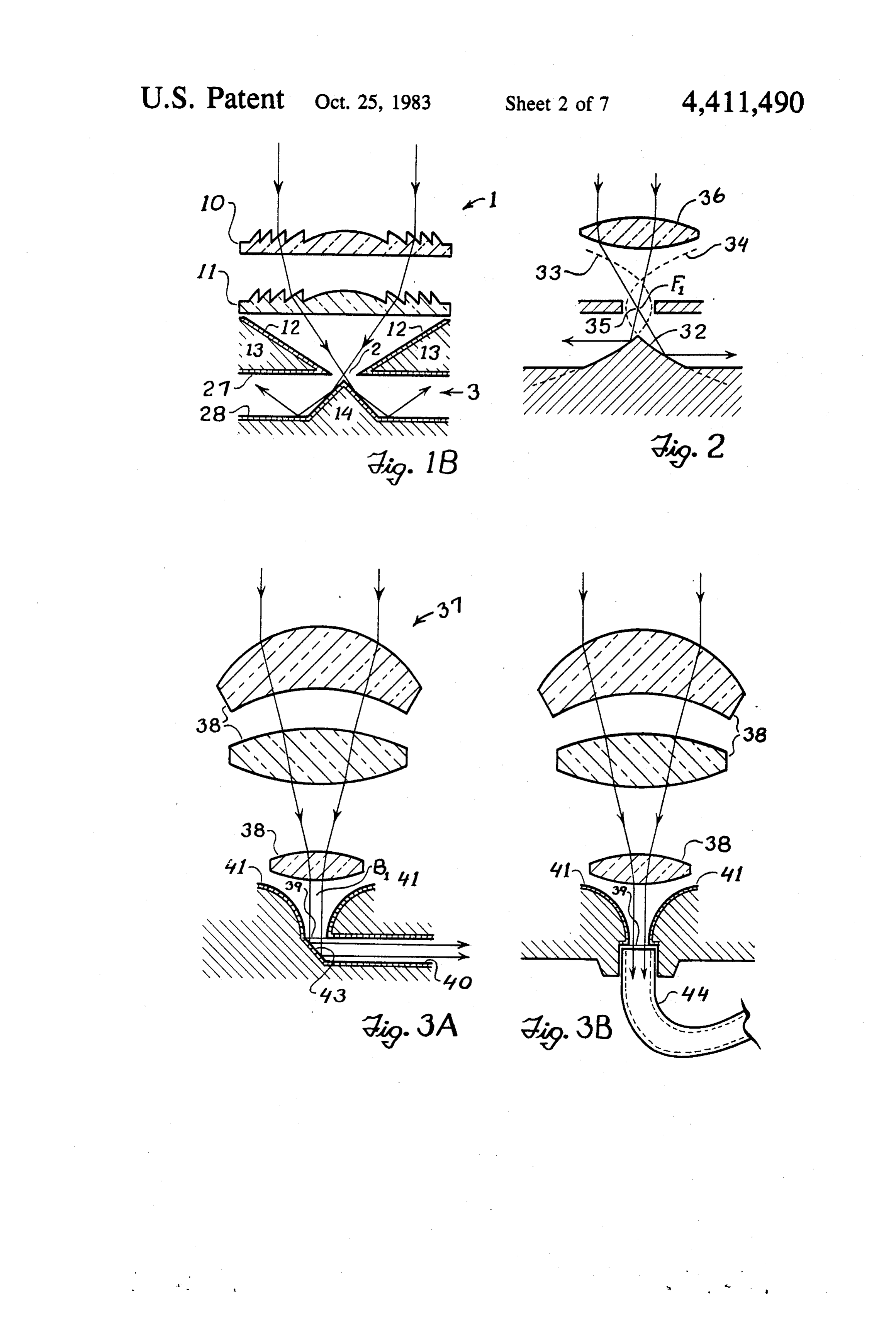
which thereafter converts the received solar radiation FIG. 1B is a cross-sectional view illustrating the placement of the lens elements of a solar gathering cell
It is further object of the present invention to provide relative to an a light-to-electricity converter which employs a light tion chamber optical window formed in the light collec of the solar collection panel illustrated in emitting fabric comprised of woven optical fibers to aid FIG. 1A; - in converting solar radiation gathered at a remote solar FIG. 2 is an alternative embodiment of a conical collection site into electricity at an optimum utilization 50 mirror for use in the light collection chamber of the site.
It is also an object of the present invention to provide solar collection panel illustrated in FIG. 1 B; a solar welder for converting solar radiation into pro FIG. 3A shows a modified solar gathering cell for use ductive heat energy suitable for use during welding in a solar collection panel of the present invention; operations. 55 FIG. 3B shows another modified solar gathering cell It is yet an additional object of the present invention for use in a solar collection panel of the present inven to provide a heat distributing element capable of receiv tion;
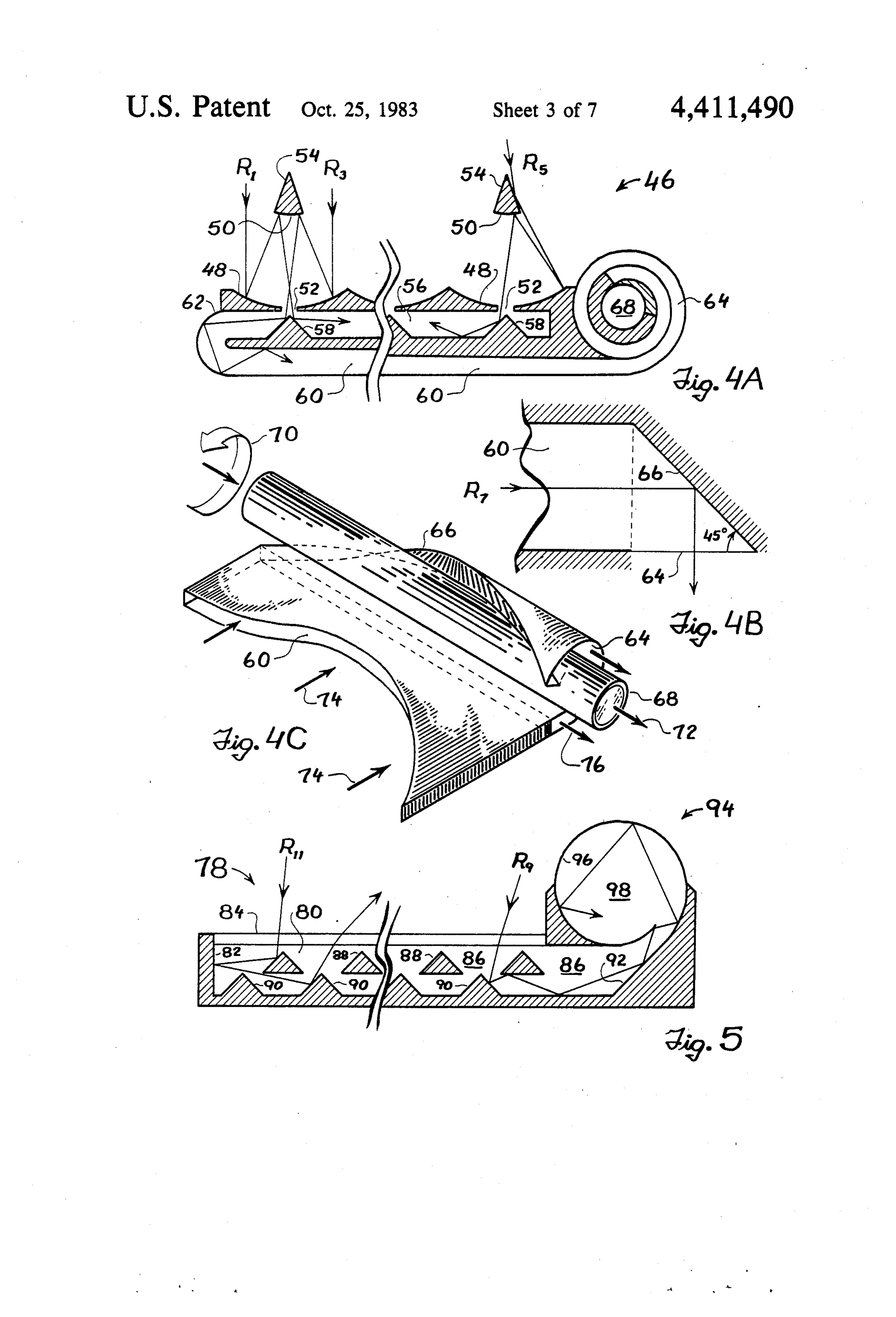
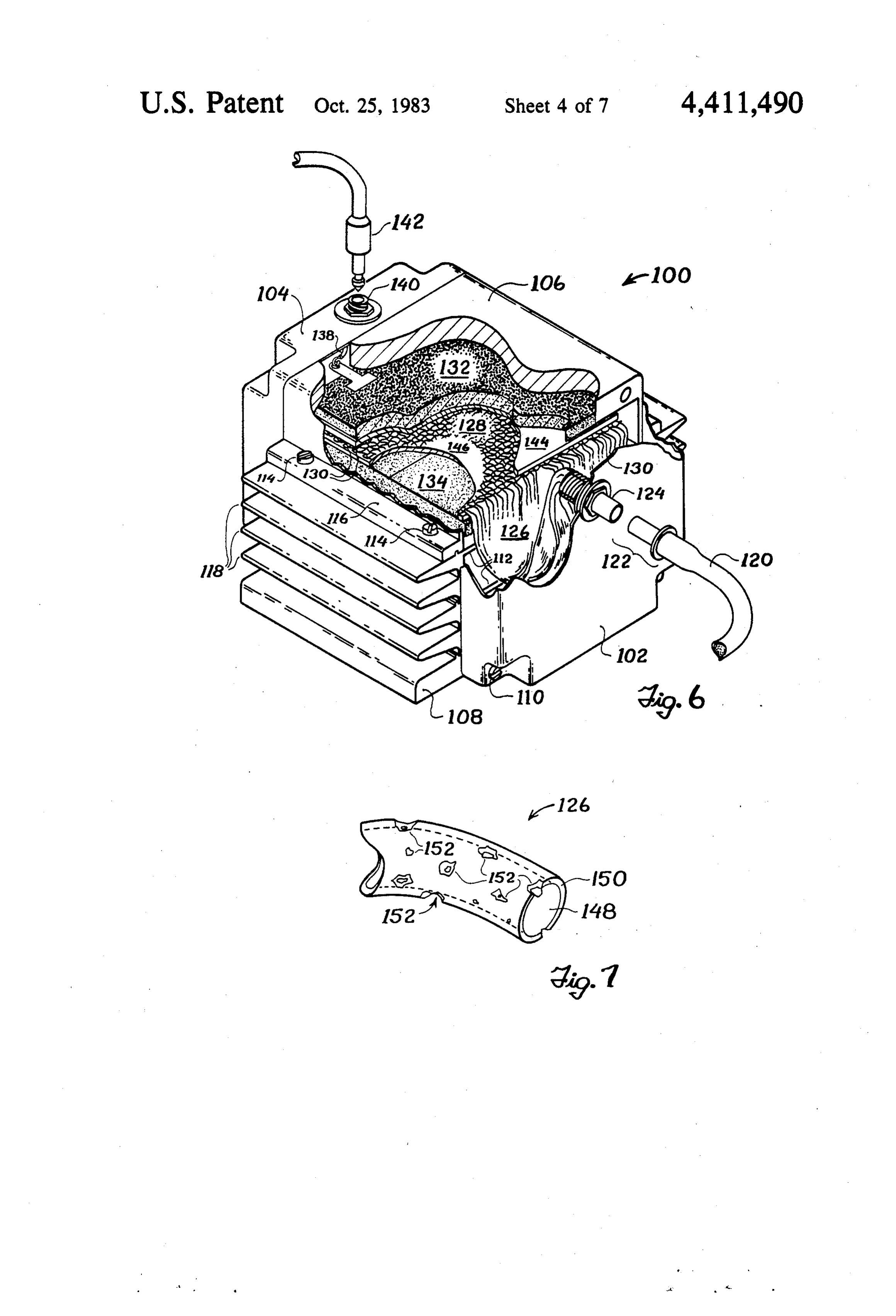
ing infrared radiation from a remote solar collection site FIGS. 4A, 4B and 4C illustrate an embodiment of an and distributing the infrared. alternative solar collection panel constructed in accor It is still another object of the present invention to 60 dance with the present invention; provide illuminating devices for receiving visible radia FIG. 5 is a cross-sectional view of another alternative tion from a remote solar collection site and for distribut embodiment of a solar collection panel constructed in ing the visible radiation so received in the form of us accordance with the present invention; able illumination. FIG. 6 is a perspective view of a light-to-electricity These and other objects of the present invention are 65 converter constructed in accordance with the present accomplished by a solar collection and utilization sys invention, wherein a light-emitting fabric is employed tem including a solar collection panel comprised of one to distribute light to solar cell arrays mounted within or more solar gathering cells which gather and focus the converter;
Page 11scan →
FIG. 7 is a detailed perspective view of a portion of two Fresnel lenses are necessary in order to minimize an optical fiber used in weaving the light-emitting fabric the distance required to focus solar radiation on win of FIG. 6; dow 2, and a small air gap preferably separates one lens FIG. 8 is a cross-sectional view of another embodi from the other. A six-sided pyramidal mirror 12 extends ment of a light-to-electricity converter constructed in from the edges of the inner Fresnel lens 11 and tapers to accordance with the the present invention, wherein an the edge of optical window 2. Pyramidal mirror 12 optical tree structure is substituted for the light-emitting serves to direct some of the sunlight improperly scat fabric of FIG. 6 as a means of distributing light to the tered away from the focal point of the Fresnel lenses solar cell arrays mounted within the converter; back toward the optical window. A plastic foam 13 or FIG. 9 is a detailed cross-sectional view of a modified O similar material may be used to fill and insulate the optical branch used in conjunction with the optical tree space between the top 27 of light collection chamber 3 of FIG. 8: and the lower surface of the pyramidal mirror 12. FIG. 10 is a side view of one type of heat distributing Again as illustrated in FIG. 1A, light collection element for radiating infrared heat in accordance with chamber 3 extends beneath solar gathering cells 1 and the present invention; S comprises a rectangular structure enclosed at the top FIG. 11 is a cross-sectional view of a heat-transfer 27, bottom 28 aid three sides 29, 30, 31 by a casing housing for use in conjunction with the heat distributing having highly reflective interior surfaces. A fourth side element of FIG. 10; 15 of light collection chamber 3 is open to permit light FIG. 12 is a cross-sectional view of a modified heat to escape therefrom. A plurality of conical mirrors 14 distributing element and heat-transfer housing for radi 20 are secured to the bottom 28 of light collection chamber ating infrared energy in accordance with the present 3 and are respectively positioned to receive solar radia invention; tion passing through the optical windows 2 from the FIG. 13 is a preferred embodiment for a solar heating corresponding solar gathering cells 1. Conical mirrors furnace wherein the heat distributing elements of FIG. 14, which in the preferred embodiment are formed with 11 are employed to supply heat for the operation of the 25 a 90° apex angle, have the effect of scattering incident furnace; - Solar radiation in a direction parallel to the top and FIG. 14 is a cross-sectional view of a solar welder for bottom planes of the light collection chamber. The solar converting infrared radiation into a point source of heat radiation scattered from the conical mirrors is subse for use during welding operations; quently reflected back and forth between the interior FIG. 15 illustrates one embodiment of a lighting fix 30 surfaces of sides 29, 30, 31 until escaping from light ture constructed to receive light from a remote solar collection chamber 3 at open side 15. Some light passing collection site in accordance with the present invention; through any given optical window 2 will initially scat FIG. 16 is a second embodiment of a lighting fixture ter off the conical mirror associated therewith only to constructed in accordance with the present invention be re-reflected from another conical mirror toward the wherein the lighting fixture is portable; and 35 top surface 27 of the light collection chamber. In such a FIG. 17 is a cross-sectional view of a recessed light case the light may escape through an optical window 2 ing fixture constructed in accordance with the present or simply reflect back and forth between the top 27 and invention for mounting in the ceiling panel of a home, bottom 28 surfaces of light collection chamber 3. In this store, office or other building. event optical loss will occur, but such loss can be mini
Best mode for carrying out the
mized through careful choice of the dimensions in
Invention
volved in constructing the solar collection panel com ponents.
The preferred embodiment for a solar collection Light escaping from light collection chamber 3 panel of the present invention will now be described in through open side 15 enters a rectangular optical en detail with reference to FIGS. 1A and 1B. The solar 45 trance window 16 formed at one end of light trap 4. As collection panel is indicated generally at 24 in FIG. A. previously discussed, light trap 4 is designed to remove Solar collection panel 24 includes an array of solar light from the light collection chamber. To this end, gathering cells 1 which gather incident sunlight, a light light trap 4 is fabricated from a single piece of optical collection chamber 3 which coherently redirects light grade plastic which is capable of channeling light from gathered by solar gathering cells 1, a light trap 4 which 50 rectangular entrance window 16 to a series of progres removes the redirected light from light collection sively elongated light guides 17 formed at the end of chamber 3, a lens system 26 which focuses and intensi light trap 4 opposite rectangular entrance window 16. fies the removed light, and a light pipe 8 which distrib Each light guide 17 has an exit window 18 through utes the intensified solar radiation to various solar utili which light can escape. The cross-sectional areas of the zation devices. For purposes of illustration, only four 55 exit windows 18 vary in proportion to the progressive teen solar gathering cells 1 arranged in a hexagonal lengths of the corresponding light guides 17 and all of pattern across the surface of solar collection panel 24 the light guides 17 may be bent, curved and stacked as are disclosed in FIG. 1A. In practice, however, each illustrated in FIG. 1A such that exit windows 18 verti solar collection panel of the present invention may con cally align to face lens system 26. Apart from rectangu tain hundreds of solar gathering cells arranged in any lar entrance window 16 and exit windows 18, all of the suitable pattern, and an actual solar collection device interior surfaces of the light trap are optically coated or may employ several such solar collection panels. processed to render the light trap highly reflective to Turning to FIG. 1B, it can be seen that each solar internal light. Thus, a substantial portion of the light gathering cell 1 consists of two Fresnel lens 10, 11 escaping through the open side 15 of light collection which receive solar radiation impinging upon the upper 65 chamber 3 is directed through light trap 4 to exit win surface of panel 24 and focus substantially all of the dows 18. If desired, the overall bulk of light trap 4 can solar radiation so received onto an optical window 2 be reduced by tapering the sides of the light trap as formed at the top 27 of light collection chamber 3. The indicated at 19 and 20.
Page 12scan →
Light leaving the exit windows 18 in light guides 17 solar collection panel matrixes may send thousands of passes through lens system 26 where a first series of watts of electromagnetic energy through a lightpipe lenses 5 reduces the angular divergence of the light to network, it may also be necessary to install safety shut form a coherent beam. A second series of lenses 7 re off switches at additional points within the various light ceives the coherent bean from lens series 5 and further channels and lightpipe trunk line. reduces the angular divergence of the light contained Numerous modifications to the solar collection panel therein to focus the beam through an optical coupler 9 of the present invention may be made for the purpose of and on into the end of lightpipe 8. Lightpipe 8, which increasing the efficiency and/or reducing the costs of comprises a bundle of optical fibers bound together and the solar collection process. For example, the solar surrounded by one or more protective coatings of gen 10 gathering cells 1 illustrated in FIGS. 1A and 1B include erally opague material, in turn serves to distribute light two Fresnel lens 10, 11 and a pyrmidal mirror 12, but from solar collection panel 24 to various remote solar other combinations of lenses and mirrors can be equally utilization sites. Both ends of the lightpipe are cut and effective. Simplified versions of the solar gathering cell polished to form flat, optically transmissive surfaces. may be constructed using only one Fresnel lens. In Where the flow of light along the lightpipe is generally 5 many applications, the pyrimidal mirrors 12 could be unidirectional, the flat optical surfaces may be referred entirely eliminated without substantial loss of light gath to as optical input and output windows in accordance ering efficiency. On the other hand, a more complex with the direction of light flow. An optical coupler such version of a solar gathering cell using three or more as optical coupler 9 is secured to each flat optical sur Fresnel lens could be fabricated to gather light ap face and serves to conduct light into or out of the ligh proaching the solar collection panel at non-vertical tpipe depending upon whether the flat optical surface is angles. The Fresnel lenses may be replaced by other functioning as an input or output window. Although focusing elements such as conventional lenses or grated hundreds or even thousands of optical fibers can be parabolic refractive indexed rod lenses to provide lens bound together in the lightpipe, the bundled fibers and systems capable of narrowing the angular dispersion of associated coatings are arranged such that the resulting 25 the collected sunlight focused through optical windows lightpipe exhibits some degree of flexibility. Lightpipes 2. Any of the lenses employed in the various lens sys can vary from one-eighth of an inch to over an inch in tems could be fabricated from transparent glass, plastic diameter. or other suitable optical material and all lenses lying in If desired, a light channel 6 for carrying light from the same plane in a solar collection panel can be molded adjacent solar collection panels (not shown) may be 30 in a single sheet. Baffles would then be placed between positioned atop the stacked light guides 17. Light leav the various solar gathering cells to prevent light col ing the transparent face 22 of light channel 6 is com lected by one cell from crossing over into the lens sys bined in lens system 26 with the light leaving exit win tem of an adjacent cell. The baffles could contain highly dows 18 and is likewise focused into optical coupler 9 reflective surfaces to form in essence, vertically stand and lightpipe 8. Light channel 6 is fabricated from a 35 ing mirrors between each layer of lenses. These mirrors solid piece of optical quality plastic and, in a manner would also serve as structural supports for keeping the analogous to light trap 4, contains surfaces highly re layers of lenses spaced at an optimum distance from one flective to interior light. A rear optical window 21 can another. The various solar gathering cells could addi be formed in light channel 6 to serve as a focal point for tionally be arranged along more than one light gather light beamed from the exit windows in the light trap of 40 ing surface in a solar collection panel, or the panel could an adjacent solar collection panel (not shown) through be shaped to form, a curved light gathering surface. an additional series of lenses (not shown) similar to lens A further variation in the construction of the solar series 5. Optical window 21, if employed, has a greater collection panel of the present invention can employ a cross-sectional area than the cross-sectional area of means such as a multiple layer interference film to split optical window 22. 45 light collected by the panel into physical and infrared The output of the solar collection panel 24 illustrated components. U.S. Pat. No. 3,314,331, for example, is in FIG, 1 is focused into a single optical coupler 9 and sued to Wiley on Apr. 18, 1967 and incorporated herein lightpipe 8. In practice, however, a plurality of solar by reference, discloses an interference film suitable for collection panels are usually mounted in a large rectan this purpose. The interference film is mounted within gular matrix arrangement on the roof of a building or 50 light trap 4 and the electromagnetic components de other solar collection site, and the simple optical cou rived therefrom are separately directed through indi pler associated with the last panel in each matrix row of vidual light guides and optical networks, each of which solar collection panels is replaced with an optical merge is similar to the light channel 6, lens system 26 and device. A lightpipe trunk line of much greater cross lightpipe 8 illustrated in FIG. 1. The optical network sectional area than lightpipe 8 can then be strung along 55 carrying visible radiation can supply light for interior the edge of the solar collection panel matrix between illumination in a residence or commercial building, the optical merge devices. Light transmitted through while the infrared optical network may be used to fur the light channels associated with each matrix row, building. nish radiant heat for a heating or hot water unit in the such as light channel 6, is then combined in the lightpipe trunk line via the optical merge deices with light re A more efficient means for forming a light collection ceived from the light channels of other matrix rows to chamber for use with the present invention may be seen form a single high intensity beam in the lightpipe trunk in FIG. 2. Each of the conical mirrors 14 secured to the line. Thereafter, the lightpipe trunk line distributes the bottom of light collection chamber 3, having 90 apex high intensity beam to solar utilization sites. In order to angles as illustrated in FIGS. 1A and 1B, is replaced by permit maintenance or installation work at various 65 a conical mirror 32 having non-linear reflective surfaces points in the light distribution network, optical "on-off" formed in the shape of parabolas when viewed in cross switches can be positioned at appropriate locations section. The parabolas, such as 33 and 34, have a center along the lightpipe network. Moreover, because large of focus F1 located at the center of the corresponding 13 optical window 35. A lens element 36 positioned above within the solar collection panel is eliminated and the optical window 35 is placed at a predetermined distance radiation gathering efficiency of the panel is corre from the optical window such that any light rays im spondingly enhanced.
pinging on lens element 36 are focused through point Where the simultaneous gathering of infrared, visible F1 and reflect from the parabolic sides of conical mirror 5 and ultraviolet radiation is desired, solar collection pan 32 in accordance with well-known geometrical formu els 46 as illustrated in FIGS. 4A, 4B and 4C can be las to continue along a perfectly horizontal path relative designed to use curved mirrors rather than lenses for to the floor of the light collection chamber. Thus, light gathering the radiation. Incoming radiation waves R1 losses due to reflection between the floor and the top of and R3 first strike a parabolic mirror 48 and are re the light collection chamber are minimized, and the O flected to a section of a spherical mirror 50 which fo light rays reaching the light trap at the edge of the light cuses the radiation waves through an optical window 52 collection chamber are collimated to a greater degree formed in the center of parabolic mirror 48. A conical than would otherwise be the case. mirror 54 caps the spherical mirror 50 to enable the The preferred embodiment of the solar collection gathering of radiation waves such as Rs which would panel illustrated in FIG. 1A combines a high light gath 15 otherwise be lost. Radiation passing through optical ering efficiency with relative ease of fabrication. A window 52 enters a collection chamber 56 similar to the more complex arrangement of components can never light collection chamber 3 in FIG. 1A and is reflected theless be employed to achieve a theoretical light gath from a conical mirror 58 similar to conical mirror 14 in ering efficiency approaching 100% for light incident at FIG. A. Conical mirror 58 acts to direct radiation from right angles to the panel surface. Turning to FIG. 3A, a 20 collection chamber 56 into a radiation trap 60 which solar gathering cell 37 utilizing a plurality of lenses 38 extends from one end 62 of solar collection panel 46 and collects solar radiation over a wide angular range and then curves underneath the solar collection panel to focuses the radiation so collected into a narrow vertical conduct radiation therefrom. As with light trap 4 in beam B with a minimum of angular dispersion. The FIG. 1A, radiation trap 60 may be fabricated from a narrow beam is passed through an optical window 39 single piece of optical grade plastic having an external and into a light collection chamber 40 which is uniquely coating of optically reflective material such that radia associated with solar gathering cell 37 and has a small tion traveling through radiation trap 60 from collection cross-sectional area relative to the cross-sectional area chamber 56 undergoes total internal reflection. The of light collection chamber 3 in FIG. 1A. Curved, mir internally reflected radiation escapes from the trap rored surfaces 41 on either side of optical window 39 30 through an exit window 64 at the end of solar collection may be employed to redirect radiation inadvertently panel 46 opposite end 62.
falling outside of beam B back through optical window As seen to best advantage in the plan view of FIG. 39. A 45 mirror 43 is positioned below optical window 4B, exit window 64 is parallel to the longitudinal axis of 39 at the end of light chamber 40. Beam B, together radiation trap 60. A mirrored surface 66 formed along with any incidental radiation redirected through optical 35 the end of radiation trap 60 at a 45° angle relative to exit window 39 by curved, mirrored surfaces 41, impinges window 64 serves to redirect radiation waves from the on 45 mirror 43 and is reflected in a horizontal direc interior of radiation trap 60 through exit window 64. tion without scattering. Light collection chamber 40 For example, a radiation wave R7 traveling in a direc serves as a light guide for conducting the horizontally tion parallel to the longitudinal axis of radiation trap 60 traveling radiation away from the solar gathering cell 40 is reflected by mirrored surface 66 and escapes radiation 37, and all of the interior surfaces of light collection trap 60 via exit window 64 in a direction generally chamber 40 are coated with a highly reflective material. perpendicular to the plane of the exit window. Refer As previously indicated, a light collection chamber is ring to FIG. 4C, the tip of radiation trap 60 containing individually associated with each solar gathering cell exit window 64 and mirrored surface 66 may be rolled 37. Consequently, a single solar collection panel con 45 about a lightpipe 68 as indicated by arrow 70 in order to structed using the solar gathering cells of FIG. 3A reduce the overall space necessary to accommodate the would contain a large number of light collection cham exit window. Lightpipe 68 functions to conduct radia bers such as light collection chamber 40. The individual tion from an adjacent solar collection panel (not shown) light collection chambers meet at the edge of the solar in the direction of arrow 72. Radiation traveling parallel collection panel, where they are all arranged to direct 50 to the longitudinal axis of radiation trap 60, as indicated light toward a lens system such as lens system 26 in by arrows 74, is reflected through exit window 64 by FIG. 1A. It can be seen that the use of lenses 38 and 45 mirrored surface 66 and generally exits trap 60 in the mirrors 43 in conjunction with individual light collec direction indicated by arrows 76. If desired, a lens sys tion chambers 40 substantially eliminates the scattering ten (not shown) may be used to merge the radiation of solar radiation within the solar collection panel, and 55 leaving exit window 64 with the radiation traveling hence essentially all of the light entering the panel may through lightpipe 68 in a manner analogous to the merg be gathered and made available for subsequent distribu ing of light from exit windows 18 and light channel 6 by tion to solar utilization devices. lens system 26 in FIG. 1A.
FIG. 3B illustrates a modification of the solar gather FIG. 5 illustrates another type of solar collection ing cell of FIG. 3A, wherein like elements are desig 60 panel 78 constructed without lens elements. Radiation is noted by like reference numerals. 45' mirror 43 and admitted to a collection chamber 80, the interior walls light collection chamber 40 of FIG. 3A are replaced by 82 of which are coated with a mirror-type substance, an individual optical fiber 44 which is coupled directly via a simple sheet of optical glass 84 having a relatively to the optical window 39. The various optical fibers low index of refraction. Collection chamber 80 is filled from each solar gathering cell are then merged to form 65 with a transparent optical grade material 86 having a a lightpipe for directing solar radiation from the solar relatively high index of refraction, and a series of coni collection panel to a utilization device. As is the case cal mirrors 88 are suspended within the optical material with the FIG. 3A embodiment, scattering of light 86. All external surfaces of the mirrors 88 are highly 14 reflective. In addition, a series of conical mirrors 90 cal fibers are segrated from one another for the purpose with highly reflective exterior surfaces are positioned at of transmitting light to respective LEC compartments. various intervals along the floor of collection chamber The individual optical fibers 126 of each grouping are 80. A tapered portion including an inclined, mirrored thereafter arranged within corresponding LEC com surface 92 is constructed at one end of the collection partment to form the warp of a piece of light emitting chamber, and terminates in a spiral shaped mirror 94 fabric 128, as disclosed in co-pending application Ser. having a highly reflective interior surface 96. Mirror 94 No. 007,592 filed Jan. 29, 1979 to the inventor of the encloses a cavity 98 which acts as a radiation trap for present invention. The woof of light emitting fabric 128 conducting radiation away from collection chamber 80 may be formed from optically inert fibers 130 if desired, and which may also be filled with a transparent, highly O but in any event fabric 128 is designed to radiate light at refractive optical grade material. One end of cavity 98 a uniform intensity across the entire fabric surface. Two may be capped with a flat mirror (not shown) lying in a Solar cell arrays 132, 134 respectively positioned above plane parallel to the plane of FIG. 5. The other end of and below light emitting fabric 128 function to convert cavity 98 is left uncovered to serve as an exit window light radiated from the fabric into electricity. Each solar for the radiation conducted therethrough. A radiation 15 cell array may be comprised of one or more conven wave such as R9 traveling toward solar collection panel tional solar cell elements which generate electrical cur 78 passes through optical glass 84 and is reflected back rent in response to incident solar radiation. Alterna and forth between conical mirrors 88 and 90 and the tively, solar cell arrays 132, 134 may utilize various reflective surface 96 of spiral shaped mirror 94 until combinations of photogalvanic cells, such as those dis leaving cavity 98 through the aforementioned exit win closed in U.S. Pat. No. 4,080,488 issued to Chen et all on dow. Due to the simplistic construction of solar collec Mar. 21, 1978 or U.S. Pat. No. 4,138,532 issued to Chen tion panel 78 it should be noted that an occasional radia on Feb. 6, 1979, to store as well as generate electrical tion wave such as R11 will enter collection chamber 80 energy. The current from each solar cell array is col only to be reflected back toward optical glass 84 at an lected at a terminal lug 136 and is conducted along an angle greater than the critical angle of the glass. Al 25 electrical lead 138 to a female electrical connector 140, though radiation wave R1 will thus be lost for useful The total electrical output from all of the LEC com purposes, if proper care is exercised in formulating the partments is removed from the LEC via a male connec dimensions of solar collection panel 78 this type of loss tor 142.
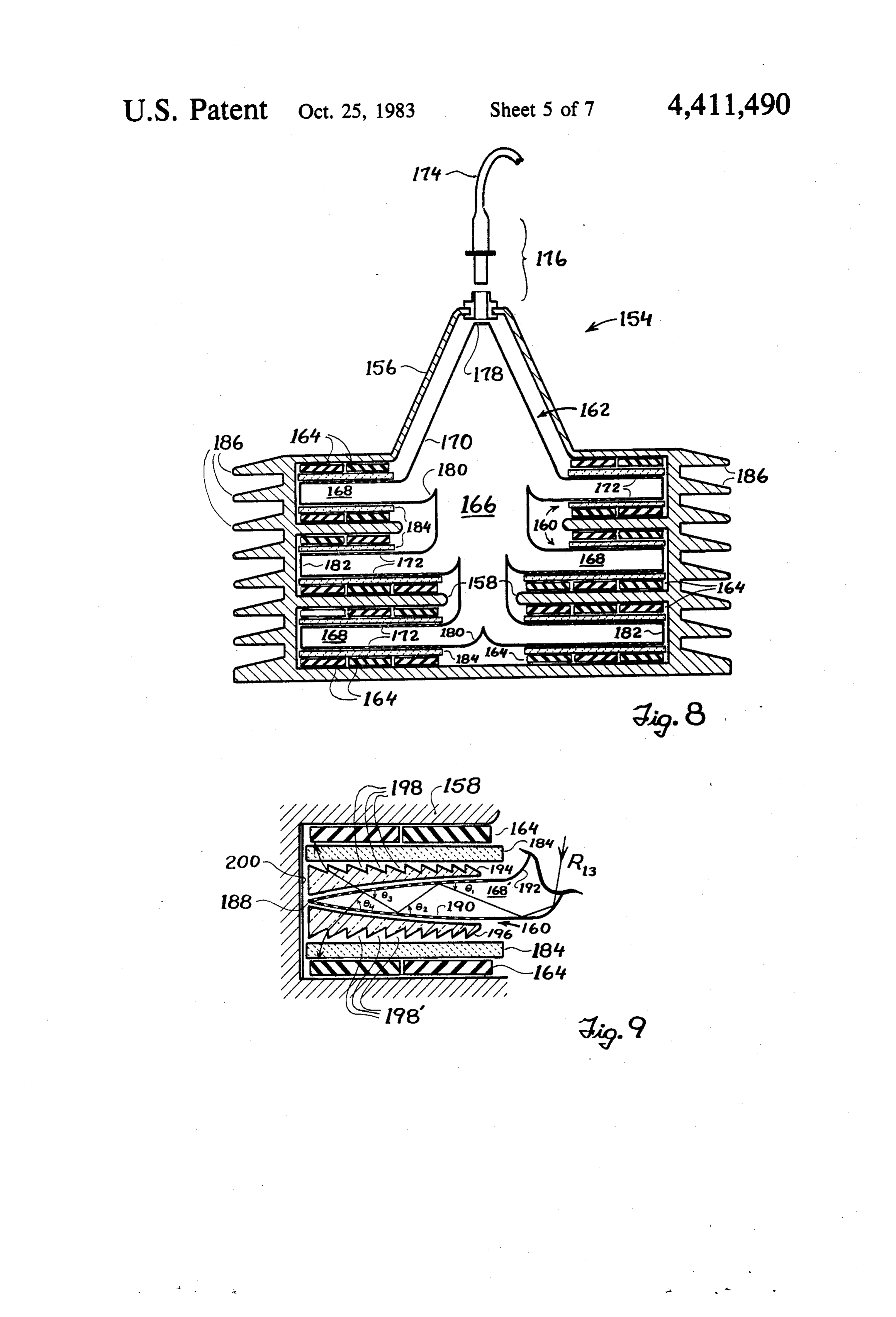
can be minimized. If desired, two sheets of photochemical glass 144, 146 As previously discussed, incident radiation gathered may be respectively inserted between light emitting and focused by any of the solar collection panels illus fabric 128 and photocell arrays 132, 134. Photochemical trated in FIGS. 1 through 5 may be conducted through glass sheets 144, 146 are highly transparent to low or light pipes such as light pipe 12 illustrated in FIG. 1 to medium intensity light but darken slightly in the pres a solar utilization device positioned in an optimum utili ence of high intensity light. Thus, the sheets act to pre zation site. One such device, in the form of a light-to 35 vent excessive light intensities from damaging the LEC electricity converter 100 (hereinafter referred to as an solar cell arrays. The solar cell arrays can in turn be LEC) is shown in FIG. 6. LEC 100 includes end covers operated at maximum efficiency for a far greater pre 102, 104 fastened to top and bottom portions 106, 108 by centage of time, inasmuch as the LEC components can bolts 110. End covers 102 and 104 may be constructed be designed to provide total saturation of the individual from sheet metal or other suitably durable material, solar cells at a light intensity less than the peak intensity while top and bottom portions 106, 108 may comprise of light received from the solar collection panels when thick aluminum extrusions. A plurality of parallel sup the sun is shining brightest. On those days when the sun porting plates 112 integrally fabricated from yet another does produce maximum light intensity, excess radiation aluminum extrusion are placed in sandwich fashion reaching the LEC will be harmlessly dissipated by the between the top and bottom portions 106, 108 to form a 45 photochemical glass sheets 144, 146. series of compartments in the interior of the LEC. For FIG. 7 illustrates in detail the individual optical fibers the sake of clarity, only the uppermost compartment is 126 which together constitute the warp for the various depicted in the cut-away view of FIG. 6. The support pieces of light emitting fabric 128. Optical fibers 126 ing plates 112, which may be secured in position by include a core material 148 surrounded by cladding 150. bolts 114 inserted through appropriate holes (not SO During manufacture the optical fibers are mechanically shown) bored in a lip 116 on topportion 106, terminate, or chemically deformed by etching, sandblasting, heat on both sides of the LEC in a series of cooling fins 118. treating or the like to create pits or apertures 152 which The cooling fins complete the enclosure of the LEC, penetrate cladding 150 to expose the core material 148. and additionally provide a means to disipate heat gener The resulting irregularities in the core material disrupt ated in the LEC during the light-to-electricity conver 55 the uniform internal reflecting properties of optical sion process. fiber 126 and permit some of the light traveling along Light gathered at a solar collection panel (not shown the fiber to escape through the apertures 152 into the in FIG. 6) is conducted to LEC 100 by a lightpipe 120 surrounding environment. The deformation operation is and passes through end cover 102 to the interior of the controlled such that more apertures per unit length LEC via an optical coupler assembly comprising male. occur on he portion of the optical fibers 126 lying coupler 122 and female coupler 124. Light emerging furthest frnm the source of light. Consequently, the net from the female coupler 124 is next uniformily dispersed intensity of light leaking from or emitted by the optical into a plurality of optical fibers 126 attached to the inner fibers 126 can be kept at a uniform value over the entire end of the female coupler. For this purpose, female fiber length, and the light emitting fabric 128 subse coupler 124 may take the form of a fiber optic bundle 65 quently formed from optical fibers 126 will provide terminator such as that disclosed in U.S. Pat. No. even illumination across the entire fabric surface. "Hot 3,912,392, issued to Hudson on Oct. 14, 1975 and incor spots" which may be present due to unusually large porated herein by reference. Various groupings of opti apertures 152 created during the deformation operation 15 may be minimized by adjusting the thickness of photo protects the optical and conversion components of the chemical glass sheets 144 and 146 to diffuse any exces LEC. The inner surfaces of housing 156 together with a sive amount of light over larger areas of the solar cell series of support arms 158 projecting inwardly from the arrays 132, 134 positioned on either side of the light sides of the LEC serve to divide the interior of the LEC emitting fabric. into various compartments 160. In lieu of the light emit The optically inert fibers 130 which constitute the ting fabric 128 of FIG. 6, an optical tree 162 is employed woof of light emitting fabric 128 may be fabricated from to distribute light to a plurality of solar cell arrays 164 either transparent or reflective material, but the use of mounted within compartments 160. Optical tree 162 is any type of light absorbing fibers should be avoided in fabricated from a single piece of optical grade plastic order to prevent loss of any light radiated from the O formed by injection mold casting, and includes a trunk optical fibers 126. In the preferred embodiment of the portion 166 with a plurality of optical branches 168 present invention, inert fibers 130 are thin metallic wires radiating therefrom. Each optical branch 168 may ex such as chrome plated copper wires which both reflect tend around the entire circumference of the trunk por light and conduct heat from the interior of the LEC to tion 168 in true three dimensional fashion. Alternately, cooling fins 118. Although not specifically illustrated in 15 two sets of branches can radiate from opposite sides of FIG. 6, the ends of the metallic fibers may be attached trunk portion 166 as indicated in FIG. 8 and two addi to the interior surfaces of the cooling fins to assist in the tional sets of branches can radiate along planes horizon heating conducting process. If desired, additional metal tally perpendicular to the plane of FIG. 8 on either side lic fibers (not shown) may be woven in parallel with of the Figure. The surfaces 170 of optical tree 162 repre optical fibers 126 to further reflect light toward solar 20 sented in FIG.8 by solid lines are covered with a highly cell arrays 132, 134, and to further conduct heat from reflective mirror coating, while the optical tree surfaces the interior of the LEC. 172 represented by dashed lines are at least partially Numerous modifications of the LEC illustrated in transparent. Light from lightpipe 174 enters the LEC FIG. 6 are possible. For example, an optical mixer ele 154 via optical coupling means 176 and passes into opti ment may be included as part of female coupler 124 to 25 cal tree 162 through an optical window 178 formed at enhance the uniform distribution of light among optical one end of trunk portion 166. Curved sections 180 link fibers 126. Alternatively, the single female coupler 124 ing the optical branches 168 to trunk portion 166 are may be replaced by several couplers arranged at differ covered with the aforementioned mirror coating in a ent locations on the LEC end cover 102, or female manner such that each optical branch captures some of coupler 124 may be eliminated entirely in favor of a 30 the light received through optical window 178. Light light pipe assembly which runs directly into individual captured by the branches 168 in turn escapes through LEC compartments. Light emitting fabric 128 may be transparent surfaces 172 and impinges upon the solar treated with various coatings having specific optical cell arrays 164 to produce electrical current. Mirrored properties in order to produce more desirable distribu ends 182 of optical branches 168 reflect light reaching tions of light within the LEC compartments, and the 35 the end of the optical branches back toward the trans light emitting fabric may be fused or laminated between parent surfaces 172. If desired, the intensity of light the two sheets of photochemical glass 144 and 146. The escaping through surfaces 172 can be made uniform by photochemical glass sheets themselves may be replaced covering the areas of surfaces 172 nearest the trunk by oridnary glass or other transparent materials such as portion 166 with an optical material having partially soft plastic or glass fiber mats. Sheets formed from soft 40 reflective and partially refractive properties while leav plastic or glass fiber mats will of course compress some ing areas of surfaces 172 furthest from trunk portion 166 what when the LEC is bolted together, thereby forcing completely transparent (i.e., completely refractive). the solar cell arrays 132, 134 into a snug fit against the Photochemical glass sheets 184 may be inserted be top and bottom surfaces of the various LEC compart tween the various optical branches 168 and solar cell ments. If desired, one of the solar cell arrays in each 45 arrays 164 to protect the arrays from damage due to compartment can be removed to simplify the LEC excessive light intensities. Cooling fins 186 formed construction. When only one array of solar cells re around the outside of the LEC 154 assist in dissipating mains per compartment, the light emitting fabric associ test generated during the light-to-electricity conversion ated therewith will be manufactured such that light process.
only radiates from the fabric surface facing the array 50 The enlarged cross-sectional view of FIG. 9 illus while the fabric surface opposite the array will be cov trates one optical branch 168 of an optical tree wherein ered with a reflective mirror to direct light back toward a more complex arrangement of optical elements is the array. employed to distribute light more evenly across the The end covers 102, 104 of the LEC can be enlarged faces of a solar cell array. As in FIG. 8 the solar cell to include electrical components such as storage batter 55 arrays 164 and the photochemical glass sheets 184 are ies in accordance with the particular circumstances of positioned within a compartment formed by supporting LEC utilization. A suitably minaturized LEC could be arms 158 to receive light from the optical branch 168". mounted on a portable appliance and employed with a In the FIG. 9 embodiment of the present invention, flexible lightpipe in a manner analogous to a conven however, optical branch 168 is tapered rather than tional electrical extension cord hookup. When the LEC 60 rectangular in shape, curving toward an apex 188 at the is secured in a stationary mode, he tradiating from the far end of the LEC compartment 160. Transparent areas cooling fins can provide a source of heat energy. Air or 190 on the outer surface of the optical branch are again water can then be circulated around the LEC to effect indicated by a dashed line and mirror coated outer sur a heat transfer function. faces 192 of the optical branch are represented by solid A second embodiment of an LEC constructed in 65 lines. Two optical glass or plastic elements 194, 196, accordance with the present invention, indicated gener each containing a plurality of grooves 198, are respec ally at 154, is illustrated in cross-section in FIGS. 8 and tively fitted to the top and bottom of optical branch 168 9. LEC 154 includes a housing 156 which surrounds and between the optical branch and photochemical glass 16 sheets 184. Grooves 198 are cut at an angle such that parent plastic material or the like, would be designed to light entering either element 194 or 196 always emerges float in water with the light gathering surfaces of the from one of the vertical faces of the grooves to strike panel facing skyward. The inherent flexibility of the optical glass elements 184 and solar cell arrays 164. A plastic would enable the entire panel array to bend with mirrored surface 200 may be positioned at the terminus ease, thus preventing structural distortion or other dam of compartment 160. A light ray such as R13 entering age by allowing the entire panel array to conform to the optical branch 168' is reflected between the mirrored motion of the waves. Collected sunlight would be chan surfaces 192 at the top and bottom of the optical branch neled into optical fiber lightpipes and conducted to until the transparent area 190 on the surface of the opti LEC arrays or other devices for conversion into elec cal branch is reached. As FIG. 9 indicates, the curva 10 tricity, heat or usable light. The solar devices may be ture or taper of optical branch 168' causes light ray R13 mounted at fixed locations on either the seashore or to strike surface 190 at progressively greater angles 81, seabottom or they may be carried by divers with suit 62, 63 and 64. In other words, due to the curvature of ably constructed lightpipe delivery systems. Alterna surface 190, 64.63 62 0. Consequently, for any given tively, large solar collection panel arrays could be light ray there is a lesser chance that the shallower 15 towed behind a ship to provide some or all of the light, angles of incidence 01 and 62 will be greater than the heat and electric power required by the ship. critical angle (i.e., the maximum angle at which internal Flexible solar collection panel arrays will, of course, reflection occurs) of the optical branch. On the other be as usable on land as at sea. When not collecting solar hand, where steeper angles of incidence 63 and 64 occur, radiation, such arrays can be rolled up for convenient the likelihood that the critical angle will be exceeded 20 transportation and storage. Accordingly, flexible solar increases. When combined with the fact that light along collection panels in combination with suitable LEC an optical conduit such as optical branch 168' generally arrangements would prove of great benefit in providing decreases in intensity as a function of distance, the effec electrical power at campsites, construction sites, or tively increasing angle of incidence and correspond military field sites. Flexible panels could also be em ingly increasing probability of escape for any given 25 ployed as roofing material for tents, pavillions and other light ray results in a more even distribution of light temporary structures.
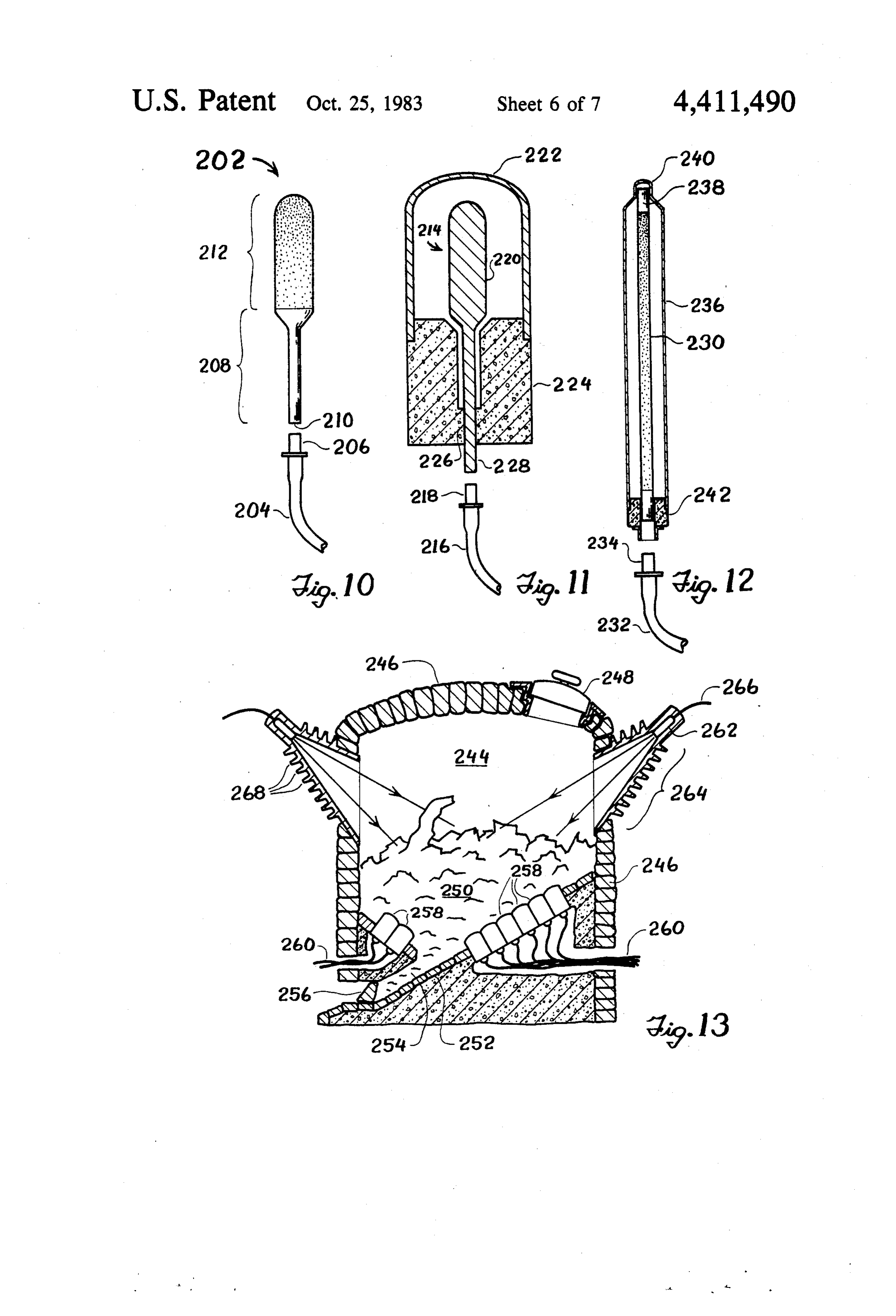
escaping from optical branch 168'. Utilization devices other than converters for produc Additional modifications to the LEC 154 described in ing electricity may be connected to the solar collection connection with FIGS. 8 and 9 will become apparent to panels of the present invention. Indeed, the ability to those skilled in the art. Unwanted wavelengths of light 30 manufacture solar collection panels and lightpipe deliv can be excluded from the LEC by employing a multiple ery systems for transmitting electromagnetic radiation layer interference film or an optical filter in conjunction to various remote sites opens up the possibility of devel with the optical window 178 of optical tree 162. A more oping entire classes of fixtures and appliances which desirable distribution of light within the optical tree operate with optical energy rather than electrical en may be achieved by replacing optical window 178 with 35 ergy, FIGS. 10 through 17 illustrate several such fix a plain lens, a Fresnel lens or a graded parabolic refrac tures and appliances for receiving and applying various tive indexed rod lens. Curved, mirrored sections 180 of combinations of visible and infrared radiation. For the trunk portion 166 may be replaced by appropriately sake of convenience, it may be assumed that the infrared angled flat mirrors, segmented mirrors, or right-angle and visible radiation are solar in origin, and are col prisms. The top and bottom surfaces 172 of each optical 40 lected by the solar collection panels illustrated in FIGS. branch 168 may be flat or curved, and the surfaces may 1A through 5. However, the devices of FIGS. 10 have grooves or other mechanical deformations ar through 17 are not dependent upon solar energy for ranged thereon to distribute light in a more desirable operation, and any source of electromagnetic radiation, pattern across the solar cell arrays 164. The grooved including radiation emitted from combustion processes, optical glass elements 194, 196 depicted in FIG.9 may 45 incandescent light bulbs or lasers may actually supply be integrally combined with photochemical glass sheets the operating power.
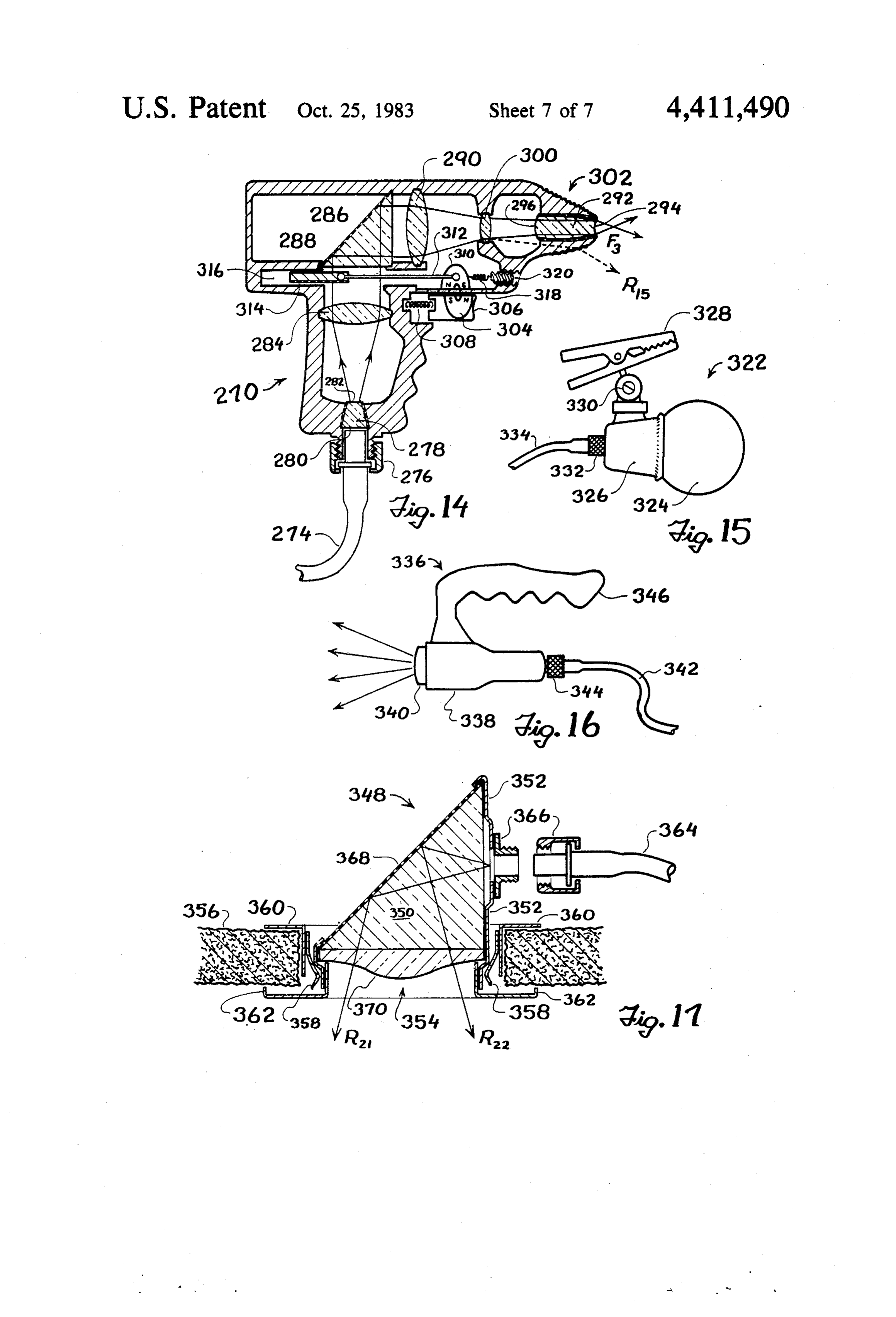
184 as a means of reducing the number of optical ele The basic design for a heat distributing element is ments in each LEC compartment. Alternately, the shown in FIG. 10. The heat distributing element 202 grooved optical glass elements may be replaced by consists of a single piece of quartz or other high melting other types of lens elements or eliminated altogether. 50 point substance transparent to infrared radiation. The Both the mirrored ends 182 of optical branches 168 in infrared radiation is supplied to heat distributing ele FIG. 8 and the mirrored surfaces 200 positioned at the ment 202 through a lightpipe 204 connected to a solar terminus of compartments 160 in FIG. 9 may be fabri collection panel employing a multiple layer interference cated in concave or convex curved fashion to further film of the type disclosed in the above-mentioned U.S. enhance the distribution of light across solar cell arrays 55 Pat. No. 3,314,331 issued to Wiley. The infrared radia 164. Finally, the optical tree 162 of FIGS. 8 and 9, tion is conducted from a suitable lightpipe coupling including the trunk portions and optical branches, may means 206 into a rod-shaped stem section 208 of heat be constructed as a hollow chamber rather than in the distributing element 202. Stem section 208 has a diame form of a solid, single piece of optical grade plastic. ter slightly greater than the diameter of light pipe 204 Such a chamber would have highly reflective interior 60 and is coated with a material which inter...ally reflects walls corresponding to reflective surfaces 170 and the infrared radiation. Surface 210 of stem section 208 is transparent or beam splitting optical windows along the made optically transmissive to form an optical input areas corresponding to transparent surfaces 172. window through which radiation enters the heat distrib Another promising area of endeavor with regard to uting element. A heat radiating section 212 is formed at the present invention lies in adapting the LEC's of 65 the end of stem section 208 opposite input optical win FIGS. 6 through 9 for use in marine environments. An dow 210 by pitting or otherwise mechanically deform array of water tight non-metallic solar collection panels, ing the outer surface of the heat distributing element to panels such as might be fabricated from flexible trans permit infrared radiation entering stem section 298 to 17 escape into the surrounding atmosphere. Ideally, the industrial applications. FIG. 13 illustrates one possible spacing of the pitting is arranged such that the input embodiment of a furnace for melting scrap metal, radiation is uniformly emitted across the entire surface wherein heat distributing elements of the present inven of heat radiating section 212. tion are used to heat the contents of the furnace. The It can be seen that stem section 208 serves as both an furnace includes a furnace chamber 244 lined with fire optical mixer and a separator between heat radiating brick 246, a hatch 248 for inserting metal ingots or scrap section 212, which may become quite hot, and the opti metal 250 into furnace chamber 244, and an outside cal coupling means 206, which may not be able to with supporting shell (not shown). The floor 252 of the fur stand much heat. Radiation entering stem section 208 is nace is wedge or cone shaped and serves to funnel mol generally trapped inside by total internal reflection and O ten metal into a channel 254 at the furnace bottom. can only escape upon reaching heat radiating section Molten metal can thereafter be extracted by removing a 212 and passing through the various pits or deforma plug means 256 from the channel. A plurality of heat tions. Heat radiating section 212 is depicted as being distributing element 258 similar to heat distributing bulbous in shape, but in reality may be formed to fit any element 214 and envelope 222 illustrated in FIG. 11 are useful configuration. For example, heat radiating sec 15 arranged around the furnace floor 252 to provide direct tion 212 may be elongated with a diameter equal to the thermal contact with the lower layer of metal 250. In diameter of stem section 208. A heat distributing ele frared radiation furnishes the heat to melt the metal, and ment having an elongated heat radiating section could is supplied to the heat distributing element/envelope then be curved to form cylinders which wrap around combinations 258 via a lightpipe delivery system 260, containers, water pipes, or other volumes to be heated. Each individual lightpipe and heat distributing element On the other hand, a spherically or flat shaped heat envelope combination functions in a manner anagious to radiating section may be more advantageous for heating that previously described in connection with FIGS. 10 devices such as space heaters or evaporators. through 12 to provide high temperature heat transfer FIG. 11 illustrates a heat-transfer housing for use in between the heat distributing element/envelope combi conjunction with the heat distributing element of FIG. 25 nations 258 and the metal 250. If desired, additional 10. The heat distributing element, indicated at 214 in radiant heat can be supplied to the contents of the fur FIG. 11, again receives infrared radiation from a solar nace by focusing high intensity light on the metal collection panel through a lightpipe 216 and lightpipe through one or more lens systems 262. Lens systems 262 coupling means 218. The heat radiating section 220 of are mounted in cone shaped metal housings 264 on the heat distributing element 214 is surrounded by an enve 30 sides of the furnace and receive infrared radiation from lope 222 constructed of a high melting point metal such lightpipes 266. A series of cooling fins 268 can be as tungsten or titanium. Infrared radiation escaping formed around metal housings 264 to aid in keeping lens from heat radiating section 220 heats envelope 222, in systems 262 and the associated lightpipe coupling ar turn causing a net heat transfer to whatever object or rangements (not shown) as cool as possible. Auxiliary material is placed in contact with the envelope. An 35 heat may also be supplied to the furnace by a natural gas insulating base 224 formed from an insulating material burner (not shown) or other conventional heating ele such as quartz or firebrick secures both envelope 222 ment in order to maintain the heating capacity of the and heat distributing element 214 in fixed relationship to furnace during periods of little or no sunlight. one another. Base 224 forms a seal 226 near the bottom Another and somewhat different type of heat transfer of heat distributing element stem section 228 in order to 40 device constructed in accordance with the present in provide as much thermal insulation as possible between vention is embodied in the hand-held welder 270 for envelope 222 and the heat distributing element. The underwater use as illustrated in FIG. 14. Welder 270 space between envelope 222 and heat distributing ele comprises a pistol-shaped housing 272 fabricated from ment 214 may be vacuum filled to furnish additional metal, glass, plastic or other durable material. Where thermal insulation. 45 glass or plastic material is employed, the housing can be FIG. 12 illustrates another variation of a heat distrib made transparent to assist in locating damaged welder uting element constructed in accordance with the pres components. Solar heat radiation such as infrared radia ent invention and suitable for use in space heaters and tion is conducted from a solar collection panel (not the like. Infrared radiation from a solar collection panel shown) through a lightpipe 274 to a lightpipe coupling and interference film assembly (not shown) is con 50 means 276 and enters the welder via an optical input ducted into an elongated heat distributing element 230 window means 278 constructed from glass or other through lightpipe 232 and coupling means 234. An elon optical grade material. The sides of optical input win gated envelope 236 surrounds heat distributing element dow means 278 contain mirror coatings while the trans 230 to provide a heat transfer surface. Heat distributing mission faces are transparent with curved lens like sur element 230 is given a reflective coating 238 at the point 55 faces. The optical input window means is secured to of contact 240 between envelope 236 and the heat dis housing 272 in a manner which prevents water from tributing element, thereby preventing the envelope entering the interior of the housing. A first lens element from receiving excessive radiation at the contact point. 284 mounted inside housing 272 focuses the radiation A small insulating base 242 separates heat distributing emerging from optical input window means 278 onto element 230 and envelope 236, and additionally plo 60 the mirrored coating 286 of prism 288. Prism 288 in turn vides a structure for attaching lightpipe coupling mens serves to bend the radiation through a second lens ele 234. The FIG, 12 embodiment of the heat distributing ment 290 toward the optical output window means 292. element and envelope as just described is generally Radiation received at the optical output window means designed to produce relatively low temperatures and 292 is directed to the outside of welder 270 and focused consequently is particularly adapted for home heating 65 at an external focal point F3 to form a point source of applications. radiation with an intensity sufficient to carry out the Other configurations of heat distributing elements, welding operation. Either or both of the transparent however, can provide relatively high temperatures for transmission faces 294, 296 on the optical output win 18 dow means 292 may be curved in lens-like fashion while be formed on housing 338 to permit a user to handcarry the sides of the optical output window means are mirror projection lamp 336.
coated. Additional lens elements such as 300 may be FIG. 17 is a cross-sectional view of a recessed light placed inside housing 272 at points along the radiation ing fixture 348 as mounted in a ceiling panel of a home, path to further modify the directional and intensity store, office or other building. Fixture 348 comprises a characteristics of the radiation beam travelling through Solid right angle prism 350 partially surrounded by a the welder. The tip 302 of welder housing 272 may housing 352 and positioned in a hole 354 in the ceiling contain a colored transparent substance which will panel 356. A plurality of spring clips 358 simultaneously assist the user in positioning welder 270 when illumi engage housing 352 and plaster ring 360 formed around nated by stray rays of radiation such as R15 occasionally O the periphery of hole 354, thereby fixedly securing omitted during the welding operation. fixture 348 to ceiling panel 356. A decorative face ring A trigger mechanism in the welder is employed to 362 may be attached to housing 352 to shield spring interrupt the transmission of radiation through the clips 358 from view. Light enters the fixture through a welder housing 272 when desired. A first magnet 304 is light pipe 364 and lightpipe coupling means 366 and secured to a trigger 306 slidably mounted on the exte 15 travels directly into the solid right angle prism 350. A rior of housing 272, and a spring 308 normally biases mirrored coating 368 on one side of prism 350 acts to trigger 306 in a fully extended position. A second mag redirect all of the input light toward opening 354 and net 310 is reciprocally mounted in the interior of hous out into the room beneath the ceiling panel. Because ing 272 such that magnet 310 tracks the movement of light traveling through a lightpipe tends to emerge at magnet 304 when trigger 306 is depressed against the 20 near perpendicular angles to the cut and polished ligh force of spring 308. A push-pull rod 312 interconnects tpipe face employed in conjunction with the lightpipe magnet 310 with a sliding mirror 314. Sliding mirror 314 coupling means, generally only small intensities of light is normally positioned in the radiant path between opti would be projected into prism 350 at angles dispersed cal input window means 278 and prism 288 and thus from the optical axis of lightpipe 362. Accordingly, serves to reflect all incoming radiation back through the 25 when using a light fixture such as fixture 348 for general optical input window means toward lightpipe 274. illumination purposes it is often desirable to spread light When trigger 306 is depressed, however, magnet 304 leaving the fixture out over a wider range of angles. To slides in a direction which causes magnet 310 and asso this end, a light redistribution disk or plate 370 is se ciated rod 312 to push sliding mirror 314 back into cured to the underside of prism 350. In the embodiment compartment 316, out of the way of the incoming radia 30 of FIG. 17 redistribution disk 370 exhibits a cross-sec tion. Thereafter, an unobstructed radiant path is formed tional profile having a relatively high convex curvature between optical input window means 278, first lens around the disk center with flatter or even slightly element 284, prism 288, second lens elements 290, opti concave surfaces near the disk edges. Other redistribu cal output window means 292 and radiation focal point tion schemes such as those employing Fresnel lenses, F3. Spring 318 is used to bias magnet 310 and sliding 35 however, may be used in lieu of disk 370. The ultimate mirror 314 toward the normal interrupting or non criterion for choosing a particular disk is one of conve operating position. An adjustment screw 320 may be nience, and the only constraint imposed is that of gener used to adjust the tension of spring 318. ating a wide enough dispersion for uniform radiation Three different types of lighting fixtures suitable for from the fixture. -- connection via lightpipes to the solar collection panels 40 A number of modifications to the recessed lighting of the present invention are shown in FIGS. 15, 16, and fixture of FIG. 17 are possible. Prism 350, for instance, 17. The lighting fixture 322 of FIG. 15 is a wide disper may be replaced by a mirror mounted at an appropriate sion lighting fixture which may be used in either land or angle, or the lightpipe coupling means 366 could be undersea environments, and includes a bulb section 324 relocated at the top of the fixture to eliminate entirely joined to a short stem section (not shown). A housing 45 the need for redirecting the light. A suitable light redis 326 surrounding the stem section rigidly supports bulb tribution disk, of course, would still have to be em section 324, and is linked to a clamp structure 328 by a ployed in such an arrangement. The entire recessed ball joint 330. The bulb and stem sections are fabricated fixture could be rotatably mounted to vary the direction from a single piece of glass or plastic with translucent of light projection, and means for inserting colored characteristics such that light travelling through the 50 transparent filters in the path of the outgoing light could glass or plastic is thoroughly diffused and emerges ran be provided to add a decorator touch. domly in all directions from lighting fixture section 322. In some applications, it may be desirable to furnish The surface of bulb section 324 may additionally be lighting fixtures which can distribute either light deliv sandblasted or otherwise mechanically deformed to ered via lightpipe means or light generated within the further diffuse the emitted light. A lightpipe coupling 55 fixture itself by conventional electrical means. Combi means 332 joined to the stem section at the bottom of nation fixtures of this type could use solar light by day housing 326 serves to couple light radiation arriving and artificial light by night. Several methods of adapt from a solar collection panel (not shown) through ligh ing different light sources for projection to the same tpipe 334. The clamp and ball joint structure provides output means are possible. One method employs a com versatility in securing and adjusting lighting fixture 322 plex reflector structure having three focal points. The relative to the area being illuminated. output from a lightpipe is focused at one focial point FIG. 16 illustrates a portable projection lamp 336 and the output from an artificial light source is focused including a housing 338 with a series of one or more at a second focal point. In either case, light is subse internally-mounted lenses (not shown) and an optical quently reflected to the third focal point for transmis output window 340. Light from a solar collection panel 65 sion through a conventional projection or light disper is conducted through lightpipe 342, lightpipe coupling sion means into the rrom or area to be illuminated. means 344 and the series of lenses before radiating out of Tri-focus reflectors are typically made with two ellipti the optical output window. If desired, a handle 346 can cal reflectors having a common focus which serves as 19 the third or output focus just described. A second radiation escaping from said transparent exit window method of alternating the use of artificial and solar light means to form a coherent beam and a second series of is based upon channeling the artificial light into a ligh lenses which receive said coherent beam and further tpipe which subsequently merges in an optical merge reduce the angular dispersion of the electromagnetic device with a lightpipe carrying solar radiation. The radiation contained therein to focus said coherent bean combined lightpipe is then connected to one of the toward a predetermined point. lighting fixtures illustrated in FIGS. 15 through 17. 6. A panel structure as set forth in claim 5, including Several embodiments of the present invention have a lightpipe means for receiving said coherent beam from been specifically shown and described herein. It is un said concentrating means and for conducting electro derstood as well that additional changes and modifica 10 magnetic radiation contained in said coherent beam tions to the form and detail of the various solar collec away from said panel means.
tion and utilization devices illustrated above may be 7. A panel structure as set forth in claim 1, wherein made by those skilled in the art without departing from each said focusing means includes at least one lens ele the scope and spirit of the present invention. It is thus ment.
the intention of the inventor to be limited only by the 15 8. A panel structure as set forth in claim 7, wherein following claims. said lens elemen is a Fresnel lens. I claim: 9. A panel structure as set forth in claim 7, wherein 1. A panel structure for collecting and distributing each said focusing means includes two lens elements. electromagnetic radiation, said panel structure compris 10. A panel structure as set forth in claim 1, wherein 1ng: 20 said plurality of cell structures are arranged in a matrix (a) a radiation gathering means for gathering electro array across the top of said light collection chamber magnetic radiation incident thereon and for trans means and said top includes a corresponding plurality of mitting electromagnetic radiation so gathered; optical windows respectively formed beneath each of (b) light collection chamber means positioned to re said cell structures.
ceive the electromagnetic radiation transmitted 25 11. A panel structure as set forth in claim 10, includ from said radiation gathering means, said radiation ing a mirrored surface extending between each said gathering means including a plurality of cell struc focusing means and each said optical window. tures each having a focusing means for focusing 12. A panel structure as set forth in claim 11, wherein electromagnetic radiation incident thereon toward each said mirrored surface is constructed as a six-sided said light collection chamber means, the exterior 30 pyramidal mirror.
surface of said light collection chamber means 13. A panel structure as set forth in claim 1, wherein including at least one optical window positioned all of the interior surfaces of said light collection cham relative to each said cell structure such that the ber means except said transparent entrance window electromagnetic radiation focused by each said means are covered with a mirrored coating.
focusing means toward said light collection cham 35 14. A panel structure as set forth in claim 1, wherein ber means passes through said optical window to said light trap means includes an interference film be received by said light collection chamber means; means for dividing the electromagnetic radiation con (c) reflecting means mounted within said light collec ducted away from said light collection chamber by said tion chamber means for redirecting the electro light trap means into at least visible and infrared compo magnetic radiation received by said light collecton 40 etS.
chamber means; and 15. A panel structure for collecting and distributing (d) light trap means for capturing the electromagnetic electromagnetic radiation, said panel structure compris radiation redirected by said reflecting means and ing:
for conducting the electromagnetic radiation so (a) a radiation gathering means for gathering electro captured away from said light collection chamber, 45 magnetic radiation incident thereon and for trans said light trap means including at least one trans mitting the electromagnetic energy so gathered; parent entrance window means positioned along said radiation gathering means including lens the interior surface of said light collection chamber means for collecting radiation over a wide angular means to enable the electromagnetic radiation redi range and focusing the radiation so collected into a rected by said reflecting means to enter said light 50 narrow beam and optical window means posi trap means. tioned to receive said narrow beam of radiation, 2. A panel structure as set forth in claim 1, wherein said optical window means including an aperture said light trap means further includes a transparent exit bounded by curved mirror surfaces diverging out window means positioned at a point removed from said wardly from said aperture toward said lens means; transparent entrance window means to permit radiation 55 (b) and light transmitting means positioned to receive captured and conducted from said light collection said beam of radition from said optical window and chamber means by said light trap means to escape from operating to transmit said radiation as a single said light trap means. beam.
3. A panel structure as set forth in claim 2, including 16. The panel structure of claim 15, wherein said light a concentrating means for reducing the angular disper- 60 transmitting means includes an elongate optical fiber sion of electromagnetic radiation escaping from said having one end positioned adjacent said perture. transparent exit window means. 17. The panel structure of claim 15, wherein said light 4. A panel structure as set forth in claim 3, wherein transmitting means includes light collection chamber said concentrating means includes at least one series of means positioned to receive electromagnetic radiation lenses. 65 from said aperture, and reflecting means mounted 5. A panel structure as set forth in claim 3, wherein within said light collection chamber means for redirect said concentrating means includes a first series of lenses ing the electromagnetic radiation received by said light which reduce the angular dispersion of electromagnetic collection chamber means.
Page 20scan →
18. A panel structure for collecting and distributing (d) light trap means for capturing the electromagnetic electromagnetic radiation, said panel structure compris radiation redirected by said reflecting means and ing: for conducting the electromagnetic radiation so (a) a radiation gathering means for gathering electro captured away from said light collection chamber, magnetic radiation incident thereon and for trans said light trap means including at least one entrance mitting the electromagnetic energy so gathered; window means positioned along the interior sur face of said light collection chamber means to en (b) light collection chamber means positioned to re able the electromagnetic radiation redirected by ceive the electromagnetic radiation transmitted said reflecting means to enter said light trap means. from said radiation gathering means; O 19. A panel structure as set forth in claim 18, wherein (c) reflecting means mounted within said light collec said conically shaped mirrors are right angle cone mir tion chamber means for redirecting the electro rors 20.
having a 90 apex angle.
A panel structure as set forth in claim 18, wherein magnetic radiation received by said light collection the surfaces of said conically shaped mirrors as viewed chamber means, said reflecting means including a 15 in cross-section are comprised of parabolas. plurality of conically shaped mirrors; and sk k is is K
Provenance
- Collection
- Patents citing this work
- Pages
- 20
- Method
- pdftotext (the PDF's own text layer) + pdftoppm 300dpi page scans
- Patent office record
- patents.google.com →
- Source
- Google Patents citing-documents table
- Assignee
- Maurice Daniel
- Published
- 1983-10-25
- Transcribed from
- patentimages.storage.googleapis.com →