

patent · US4412527A
Greenhouse of an underground heat accumulation system
1 November 1983
Text
Page 1bibliographic recordscan →
United States Patent (19)
Fujie et al.
54 GREENHOUSE OF AN UNDERGROUND
HEAT ACCUMULATION SYSTEM
(75) Inventors: Kunio Fujie, Tokyo; Akinari Uchida, Ibaraki; Kazuhiko Abe, Urawa, all of
Japan Assignee: Hitachi, Ltd., Tokyo, Japan
30 Foreign Application Priority Data
Apr. 9, 1980 JP Japan .................................. 55
52 U.S.C. .................................... 126/400; 126/436;
3,815,574 6/1974 Gaydos, Jr. ......................... 126/436 3,970,069 7/1976 Pickett ................................ 126/422
4,059,146 11/1977 Gruniger ............................. 126/400 4, 1 1,189 9/1978 Dizon .................................. 126/400 4,153,047 5/1979 Dumbeck ............................ 126/400 4,265,300 5/1981 Kurimoto................................ 47/17
FOREIGN PATENT DOCUMENTS
Primary Examiner-James C. Yeung
Attorney, Agent, or Firm-Antonelli, Terry & Wands
A greenhouse of an underground heat accumulation system wherein the radiant energy of the sun or wasted thermal energy is accumulated in the soil below the floor of the greenhouse over a prolonged period of time, and spontaneous release of the accumulated en ergy into the interior of the greenhouse begins in the wintertime due to a time lag of heat transfer through the soil. The release of the accumulated energy lasts throughout the winter.
14 Claims, 5 Drawing Figures
Drawings
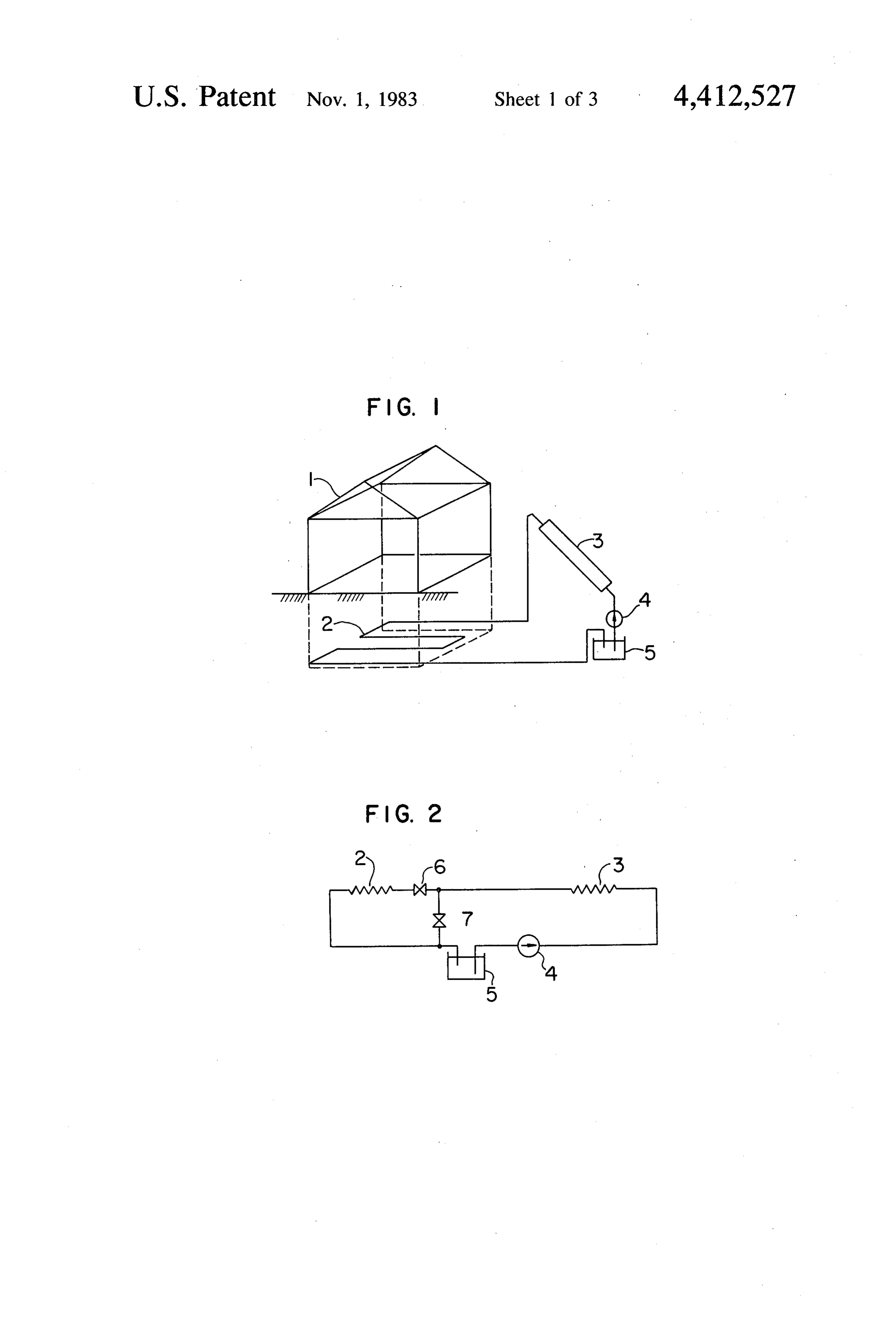
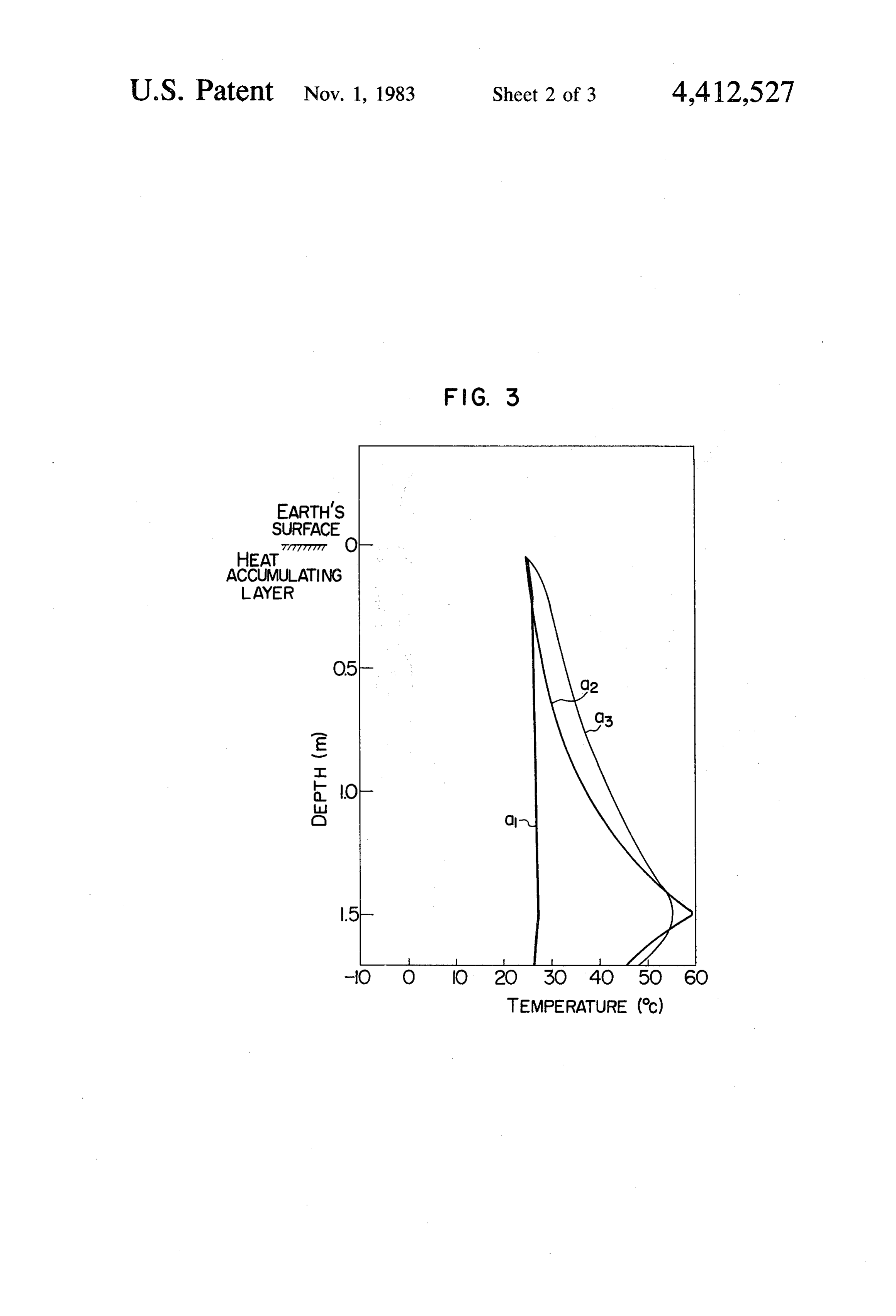
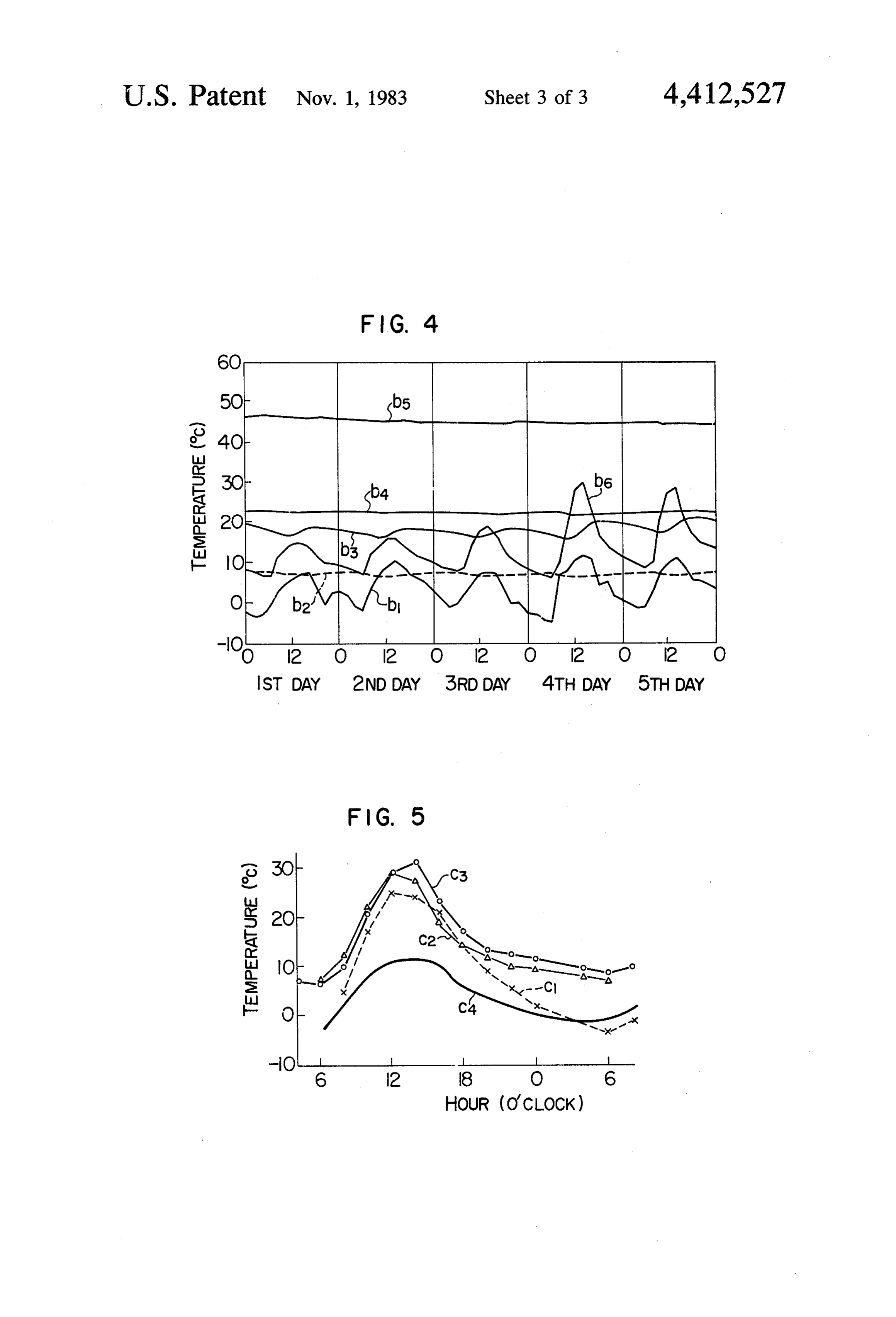
FIG. 4 is a graph in explanation of changes in temper
FIG. 5 is a diagrammatic representation of the results Thus, the invention enables the temperature in a of tests in which changes in the temperature in the greenhouse at a suitable level in winter without using greenhouse of the system of underground storing of fossil fuel.
Page 2drawing sheetscan →
Page 3drawing sheetscan →
Page 4drawing sheetscan →
Page 5scan →
FIG. 4 is a graph in explanation of changes in temper
GREENHOUSE OF AN UNDERGROUND HEAT ature occuring in various sections of the greenhouse ACCUMULATION SYSTEM shown in FIG. 1 for consecutive five days in winter; and
BACKGROUND OF THE INVENTION FIG. 5 is a graph comparing the greenhouse of the FIELD OF THE INVENTION underground heat accumulation system with green This invention relates to a greenhouse of an under houses of the prior art.
ground heat accumulation system in which radiant en DESCRIPTION OF THE PREFERRED ergy of the sun or wasted thermal energy is stored 10 EMBODIMENT under the ground for use in heating the interior of the Referring now to the drawings and, more particu green-house. larly to FIGS. 1-2, a greenhouse main body 1 has em Several different heating systems are available for bedded in the soil under its floor, at a depth of about 1.5 greenhouses of the prior art, which systems include a m, an underground radiator 2 which, combined with the stove system, a hot air system, a hot water system, a 15 soil beneath the greenhouse body 1, constitutes an un steam system and an electric heat system. They all de derground heat accumulating pend on fossil fuel as the source of energy, and the ground radiator 2 is connected section. to a heat The under collector 3 amount of the thermal energy used for this purpose is through a fluid machine 4, which may, for example, be constantly increasing with the development of cultiva a pump, and a receiver tank 5 so as to cause hot water tion of plants all the year round. Meanwhile the price of 20 heated by the radiant energy of the sun to circulate fossil fuel is also yearly increasing and this, combined with a shortage of oil, exerts serious influences on the through prises a the system. The underground radiator 2 com serpentine tube of metal evenly arranged be greenhouse industry. Thus, the need to conserve energy neath the floor of the greenhouse body 1 which, in the by switching the source of energy elsewhere from the illustrated fossil fuel has been keenly felt. In view of this situation, 25 In this embodiment, has an area of 24 m2. there have recently been made various proposals to water flowing through thetheheattemperatures adopt a system of heating with accumulated thermal at its inlet and its outlet and the collector 3, as measured differential between the energy by utilizing the radiant energy of the sun or wasted thermal energy to meet the needs of the times. inlet and outlet temperatures, are sensed by sensing In this system, excess thermal energy that has not been 30 means. When the sun shines to a desired degree, the hot consumed in the daytime is accumulated and released at water flowing through the heat collector 3 shows a night for heating purposes. Since this system is gener difference in temperature between the inlet and the ally operated on day-to-day basis for accumulation and outlet of the heat collector 3. When the difference is release of necessary thermal energy, the system suffers above a predetermined value and the outlet temperature the disadvantage that it does not satisfactorily work 35 is in the predetermined range of, for example, between when the amount of the accumulated thermal energy is 55 C. and 65 C., a valve 6 is opened and a valve 7 is small and inclement weather lasts in the wintertime in closed to actuate the fluid machine 4 so as to cause a the absence of an ancillary thermal energy source. This circulating flow of the hot water through the system of would cause the temperature in the greenhouse to drop, the underground radiator 2. In the event that the outlet thereby causing damage to the plants. 40 temperature is lower than the predetermined value range in spite of the fact that there is a temperature
SUMMARY OF THE INVENTION difference between the inlet and the outlet of the heat This invention has been developed for the purpose of collector 3, the valve 6 is closed and the valve 7 is obviating the aforesaid disadvantage of the prior art. opened so that the hot water bypasses the underground Accordingly the invention has as its object the provi 45 radiator 2 as it flows in circulation without the hot sion of a greenhouse of the underground heat accumula water flowing from the heat collector 3 to the under tion system capable of maintaining the temperature in ground radiator 2. When the difference between the the greenhouse at a suitable level in the wintertime inlet and outlet temperatures of the hot water at the heat without relying on fossil fuel. collector 3 drops below the predetermined value due to , The outstanding characteristic of the invention is that 50 a reduction in the radiation of the sun, the operation of the radiant energy of the sun or wasted thermal energy the system is stopped. In this way, the radiant energy of is stored for a prolonged period of time under the the sun is gradually accumulated in the earth below the ground on which the greenhouse stands, so that the greenhouse body 1.
thermal energy thus stored underground can begin its In the embodiment of the above construction, the hot spontaneous release into the greenhouse when the cold 55 water flows in circulation through the heat collector 3 season sets in due to a time lag in the transfer of heat and the radiator 2 connected in one system. It is to be through the soil and the release of the stored thermal understood that the invention is not limited to this spe energy can last throughout the winter. cific form of medium for transferring thermal energy, BRIEF DESCRIPTION OF THE DRAWINGS 60 Water. and that heated air may be used in place of the hot FIG. 1 is a schematic view of the greenhouse of the Alternatively, the heat collector 3 and the under underground heat accumulation system comprising one ground radiator 2 may be arranged to form separate embodiment of the invention; systems which are connected by a heat exchanger, to FIG. 2 is a diagram of the heated water system shown allow different forms of fluid to flow in circulation in FIG. 1; 65 through the different systems. For example, a gas may FIG. 3 is a graph in explanation of the distribution of be through the system of heat collector 3 and a liquid temperature in the underground heat accumulating may be circulated through the system of underground section shown in FIG. 1; radiator 2.
Page 6scan →
Accumulation of thermal energy may be started in, amount of heat accumulated or 23.5 kwh/m2 would be for example, October. Then, in about a month, the input consumed in 3.5 months.
to the underground radiator 2 will reach a constant By taking into consideration the thermal diffusivity of level of about 19.4 w/m2 per unit area. FIG. 3 provides the soil, the amount of heat accumulated underground an illustration of the distribution of temperature in the and the heat balance of the greenhouse, the optimum underground heat accumulating section in which a depth at which the underground radiator 2 is embedded curve a shows the temperature at the time of initiation below the surface of the earth will be about 1.5 m. A of heat accumulation, a curve a2 shows the temperature depth over 1 m from the surface of the earth will be an two weeks after heat accumulation has started, and a effective depth depending on the time at which heat curve as shows the temperature one month after heat O accumulation is started, the heat accumulating rate, and accumulation has started. It will be seen that in about other factors. The underground radiator 2 may be con one month, the temperature in a position 30 cm below structed such that it is surrounded by latent heat accu the surface of the earth which lies immediately below mulating material and has soil placed thereon in layers. the area in which the roots of the plants spread stands at In this heat accumulating construction, it is possible to 30° C., and the temperature near the surface of the earth 15 increase the amount of heat accumulated per unit area (3 cm) is 20° C. on an average. These temperature re and to reduce the area of the underground radiator or main substantially constant thereafter, with the atmo the length of the serpentine tube.
spheric temperature standing at 10 C. The area required for the heat collector 3 will be The depth of the underground heat accumulating described. The area required for this purpose can be section will be described. Assume that a change 6a in the 20 obtained from the relation between the amount of heat temperature in a certain plane under the ground can be input of 19.4 w/m2 per unit area referred to hereinabove expressed as 6= Asin cot. Then a change 6 in the tem and an average amount of heat collected by the heat perature in a plane parallel to the certain plane and collector a day ("average radiation from the sun'X'av spaced apart therefrom by X m can be expressed as erage time from sunrise to sunset'X“heat collecting 0x = Ae-K sin (cot-Kx), where a is the thermal diffu 25 efficiency'). Thus, the area would be 1/6 the floor sivity of the soil and K=(a)/2a) - 3. By substituting space of the greenhouse when the average radiation for o = 10 m2/h, a) = 2n/24x365 and x = 1.5 m into this October, the time from sunrise to sunset and the heat equation, a phase difference t at a point x is obtained by collecting efficiency are 814 w/m2, 6 h and 0.6, respec the following relationship: t = KX/27T = 2.2 months. This tively. By starting heat accumulation earlier than Octo relationship indicates that with the heat accumulating 30 ber, the amount of accumulated heat can be increased section having a depth of 1.5 m, the heat accumulated and the required area of the heat collector 3 can be underground at a depth of 1.5 m from the ground level correspondingly reduced. Thus, the area of the heat can reach the earth's surface on which the greenhouse collector 3 would be advantageously over 1/6 the floor stands in the coldest season, assuming that the accumu space of the greenhouse.
lation of heat can be continued up to December. Also, 35 The underground radiator 2 will now be described. by calculating the influences exerted by changes in the Let the radius, the surface area and the spacing interval mean temperature of each month on the ground level on of parallel portions of the heat dissipating serpentine the temperature of the earth below the ground level, it tube of the underground radiator 2 and the floor space is possible to obtain a reduction of 31% at a depth 1.5 m of the greenhouse be denoted by r, Sp, p and SG, respec below the ground level. Meanwhile the phase differ 40 tively. Then the ratio of the surface area S. of the heat ence between the temperature on the ground level and dissipating tube to the floor space PG Sp/Sg has the the temperature below the ground level at the depth of following relationship:
1.5 m is 2.2 months, so that the temperature of the soil in October in which heat accumulation is initiated reaches a maximum level in the year and provides an 45 advantageous condition for starting the accumulation of In the embodiment described hereinabove in which heat. The amount of heat Q accumulated at this time can the underground radiator 2 is disposed about 1.5 m from be expressed by the following equation: Q= CpA0, the surface of the earth, the amount of heat transferred where C is the specific heat of the earth, p is the density from the underground radiator 2 to the surface of the of the earth, A6 is the difference in temperature be 50 earth on which the greenhouse stands is about 0.7 tween the surface of the earth and a point which is 1.5 w/m2. C. when the ratio S/Sg is 1.0 (or p/r=27). m below the ground level, and x is the depth of the heat This value is 0.6 w/m2. C. when S/Sg is 0.1 (or accumulating section. In this equation, the amount of p/r=207) and 0.54 w/m2. °C. when S/Sg is 0.05 (or accumulated heat Q will be Q=23.5 kwh/m2 per unit p/r=407t). Thus, a large variation in the area ratio area when the specific heat C of the earth is 2.52 kJ/Kg 55 Sp/SC causes no great change in the amount of trans C., the density of the soil is 1500 kg/m3, and the floor ferred heat. For practical purposes, any value above space of the main body 1 of the greenhouse is 24 m2. 0.05 would be enough for the area ratio Sp/Sg. As to the heat balance in the greenhouse, Generally, The temperature at which the underground radiator accumulation of the radiant energy of the sun in the 2 is heated should be limited to 70° C. at maximum by surface layer of the earth in the greenhouse is carried 60 taking into consideration the effects exerted by heat on out for about eight hours a day on an average of 45 the ecology of microorganisms in the soil. Also, the w/m2 in winter, so that the amount of heat accumulated underground radiator 2 may be of any construction as per day is 360 wh/m2d. Also, release of heat from the desired so long as its heat transfer area with respect to earth into the greenhouse is carried out for sixteen hours the earth is over about 0.05 time the floor space of the a day on an average of 36 w/m2 in winter, so that the 65 main body of the greenhouse. For example, the under amount of heat dissipated per day is 576 kwh/m2. Thus, ground radiator 2 may consist of the heat dissipating the amount of heat actually consumed is 216 wh/m2d. tube alone, metal plates may be attached close to the By consuming heat at the aforesaid rate, the aforesaid surface of the heat dissipating tube or heat-transfer fins 7 may be connected to the heat dissipating tube. The heat system of long period heat storing over that of short dissipating tube may be formed of a synthetic resinous period heat storing is that the former is capable of keep material of a thermal conductivity equal to or higher ing the temperature in the greenhouse at an optimum than that of the soil. The heat dissipating tube may have level for several days even if inclement weather persists an inner wall surface which is not circular but elliptic or as compared with the latter whose performance may any other irregular shape in cross section. vary depending on whether it is fine or cloudy in the Experiments were carried out on heating the interior daytime, of the greenhouse by spontaneous heat release into the From the foregoing description, it will be appreciated greenhouse from the heat source consisting of the un that the system of storing heat underground over a derground accumulated heat stemming from the radiant 10 prolonged period according to the invention which energy of the sun collected and stored underground accumulates below the surface of the earth the radiant over a prolonged period of time, at midnight in early energy of the sun at least in autumn and releases the January when the outdoor temperature was -0.7 C. stored energy by spontaneous release to heat the green The results obtained show that the temperature stands house is capable of maintaining the interior of the green at 6.7° C. in the center of the greenhouse and at 10 C. 15 house at an optimum temperature level for the cultiva near the floor where the plants rooted in the soil grow, tion of vegetables throughout the period of severe cold and that it is possible to keep the difference between the and of achieving better results in heating the green outdoor temperature and the indoor temperature at house than the system of short period heat storing. In over 7 C. It will be seen that the condition is favorable the foregoing description, the radiant energy of the sun for cultivation of tomatoes, strawberries, pumpkins, 20 has been described as being used as a source of thermal eggplants and cucumbers which are said to require a energy to be stored in the underground heat accumulat minimum temperature of below 10 C. at night.
FIG. 4 is a diagram showing changes in temperature ing section. However, it is to be understood that the in various sections of the greenhouse of this embodi energy andis that invention not limited to this specific form of thermal wasted thermal energy may be used as ment occurring for five consecutive days in the winter 25 a source of thermal energy to be stored in the under time. The weather was cloudy on the first, second and ground heat accumulating section. third days and fine on the fourth and fifth days. In the diagram, a curve b1 represents the outdoor temperature, in the greenhouse accordingcarried
Cultivation of plants was out by usual means a curve b2 represents the temperature of the soil 25 cm spring-sown vegetables weretosown the invention in which below the surface outside the greenhouse, curves b3, b4 30 harvested at the beginning of March.inThis December and is attributed and bs represent the temperatures of the soil 3, at 27 and to not only the high temperature in the greenhouse but 147 cm below the surface, respectively, of the heat also the high temperature of the soil which promotes accumulating section, and a curve be represents the the growth of the roots.
indoor temperature of the greenhouse. In the diagram of FIG. 4, it will be seen that the indoor temperature 35 at Thus, the invention enables the greenhouse to be kept a room temperature of over 6' C. and the soil at a shows little change regardless of the weather, and that, temperature of over 16' C. by utilizing the radiant en although the temperature of the soil at a point of 25 cm from the surface outside the greenhouse is about 7.5 C., ergy of the sun or wasted thermal energy without using the temperature of the soil at a point of 3 cm from the fossil fuel, thereby making it possible to cultivate spring surface inside the greenhouse is 18 C. and rises in going 40 sown vegetables in winter.
further deeper into the earth. In view of the fact that Generally a greenhouse consumes about 2 liter/m2 of minimum, soil temperature at which cultivation of veg fossil fuel for heating purposes in one winter. If the etables can be carried out for practical purposes is about heating of the greenhouse can be effected by utilizing 18 C., this soil temperature would be considered opti the radiant energy of the sun alone, it would be possible mum for raising the aforesaid vegetables. At this time, 45 for a greenhouse of 1000 m2 to conserve 2000 liters of the temperature of the soil at a point 1.5 m from the oil. Moreover, since the radiant energy of the sun is free surface is 45 C. which has a difference of about 25 C. from the danger of polluting the air and its supply is with respect to the temperature of the soil near the inexhaustible, the utilization thereof offers advantages surface, and release of heat to the surface of the earth besides being able to conserve energy stemming from continues. 50 fossil fuel.
FIG. 5 is a diagrammatic representation of the results Thus, the invention enables the temperature in a of tests in which changes in the temperature in the greenhouse at a suitable level in winter without using greenhouse of the system of underground storing of fossil fuel.
heat over a prolonged period of time according to the What is claimed is:
invention are compared with those in the greenhouses 55 1. A greenhouse having an underground heat accu of the system of vinyl sheet house and the system of mulation system comprising a main body having heat underground storing of heat for a short period of time from a heat source accumulated underground below a by selecting days of similar weather conditions. In the floor thereof for use in heating an interior of the green diagram of FIG. 5, curves C1, C2 and C3 represent tem house, comprising:
peratures in the greenhouses of the vinyl sheet house 60 an underground radiator located at a predetermined system, short period heat storing system, and long per depth below the floor of the greenhouse, said un iod heat storing system respectively, and a curve C4 derground radiator cooperation with soil in a vicin indicates outdoor temperatures. It will be seen in the ity thereof to constitute an underground heat accu diagram that the system of long period heat storing mulating section;
shows a better performance than the system of short 65 a solar heat collector for collecting radiant energy period heat storing, much less the vinyl sheet house from the sun, said solar heat collector being ther system which lags far behind the system of long period mally connected to said underground radiator of heat storing system. An additional advantage of the said underground heat accumulating section;
Page 8scan →
a fluid heated by the radiant energy collected by said systems are thermally connected together by a heat solar collector, said fluid being circulated through exchanger.
the underground radiator of the underground heat 5. A greenhouse as claimed in claim 3 or 4, wherein accumulating section; and the fluid circulated through the solar heat collector and wherein the predetermined depth of the underground the underground radiator of the underground heat ac radiator is determined by the relationship: cumulating section is hot water.
6. A greenhouse as claimed in claim 3 or 4, wherein where: the fluid circulated through the solar heat collector and the underground radiator of the underground heat ac x= predetermined depth of the underground radiator, 10 cumulating section is heated air. t = a time period, in months, from a moment at which 7. A greenhouse as claimed in claim 4, wherein differ an accumulation of solar heat has begun until a ent types of fluid are circulated through the system of moment at which the solar heat is used in the the solar heat collector and the system of underground greenhouse, and - radiator of the underground heat accumulating section. C=a constant determined in accordance with a phys 15 8. A greenhouse as claimed in claim 1, wherein the ical property of the soil under the floor of the underground radiator comprises a serpentine tube for greenhouse; dissipating heat.
whereby the solar energy is accumulated in the un 9. A greenhouse as claimed in claim , wherein the derground heat accumulating section and utilized underground radiator comprises a serpentine tube for as a heat source in the greenhouse after an elapse of 20 dissipating heat, and metal plates connected to the ser the time t. pentine tube.
2. A greenhouse as claimed in claim 1, further com 10. A greenhouse as claimed in claim 1, wherein the prising sensing means for sensing the temperatures of underground radiator of the underground is formed of a the fluid at the inlet and the outlet of said solar heat synthetic resinous material having a thermal conductiv collector and the temperature differential between 25 ity equal to or higher than the thermal conductivity of them, said sensing means being operative to allow the the soil below the surface of the earth. heated fluid to circulate through the underground radi 11. A greenhouse as claimed in claim 1, wherein the ator of the underground heat accumulating section underground radiator of the underground heat accumu when the temperature differential is above a predeter lating section has an area for releasing heat to the soil mined value and the temperature of the heated fluid at 30 which is over 1/20 the floor space of the greenhouse. the outlet of the solar heat collector is within a predeter 12. A greenhouse as claimed in claim 1, wherein the mined range of values. solar heat collector has an area which is over 1/6 the 3. A greenhouse as claimed in claim 1, wherein the floor space of the greenhouse.
heat collector and the underground radiator of the un 13. A greenhouse as claimed in claim 1, wherein the derground heat accumulating section constitute one 35 predetermined depth of the underground radiator is at System. least 1 m.
4. A greenhouse as claimed in claim 1, wherein the 14. A greenhouse as claimed in claim , wherein the heat solar collector constitutes one system and the un physical property of the soil is at least one of thermal derground radiator of the underground heat accumulat conductivity and specific heat. ing section constitutes another system, and the two s k s k
Provenance
- Collection
- Patents citing this work
- Pages
- 8
- Method
- pdftotext (the PDF's own text layer) + pdftoppm 300dpi page scans
- Patent office record
- patents.google.com →
- Source
- Google Patents citing-documents table
- Assignee
- Hitachi, Ltd.
- Published
- 1983-11-01
- Transcribed from
- patentimages.storage.googleapis.com →