

patent · US4425907A
Reflector-coupled fluorescent solar collector
17 January 1984
Text
Page 1scan →
- 3 SR 1 17 8.4 4 : 425 O7
United States Patent (19)
Younghouse
(54 reflector-coupled fluorescent
Solar collector
75 Inventor: Lawrence B. Younghouse, Boonton,
73) Assignee: Exxon Research and Engineering Co.,
Florham Park, N.J.
Related U.S. Application Data 63 Continuation of Ser. No. 190,666, Sep. 25, 1980, aban doned.
51) Int, Cl.................................................. F24J 3/02 52 U.S. Cl. ................ a so - a as essee a a • 126/439; 126/441;
3,051,038 8/1962 Duke .................................. 126/439 3,134,906 5/1964 Henker ......... ... 126/438 3,869,199 3/1975 Cummings ... . . 126/439 3,968,786 7/1976 Spielberg ..., 126/441 4,026,267 5/1977 Coleman ....... ... 126/449 4,026,273 5/1977 Parker ............. sos is a on too prov sno 126/438
4,149,902 4/1979. Mauer et al. ... ... 126/441 4,171,003 10/1979 Forrat ................................. 36/247 4,184,895 l/1980 Oster ................................... 126/442 4,201,197 5/1980 Dismer ................................ 126/439 4,204,881 5/1980 McGrew ............................. 126/438 4,230,095 10/1980 Winston .............................. 126/438 4,246,891 1/1981 Lambert .............................. 126/438 4,264,124 4/1981 Greubel ............................ 350/96.10 4,292,959 10/1981. Coburn ... - - - - - - 126/438 4,306,542 12/1981 Reinert ................................ 126/901 Primary Examiner-Daniel J. O'Connor
Attorney, Agent, or Firm-Joseph J. Dvorak
The present invention provides a system for the collec tion of electromagnetic radiation and the transmission of that radiation to a point of use. In its simplest sense, an apparatus for the collection and transmission of elec tromagnetic radiation comprises a cylindrical fluores cent fiber, at least one end of which is optically coupled to an optical wave guide, and means for reflecting solar radiation impinging over a relatively wide area onto said cylindrical fluorescent fiber. Preferably, a com pound parabolic mirror is employed for reflecting inci dent solar radiation onto the optical fluorescent fiber. 7 Claims, 5 Drawing Figures
Drawings
Page 2drawing sheetscan →
Page 3scan →
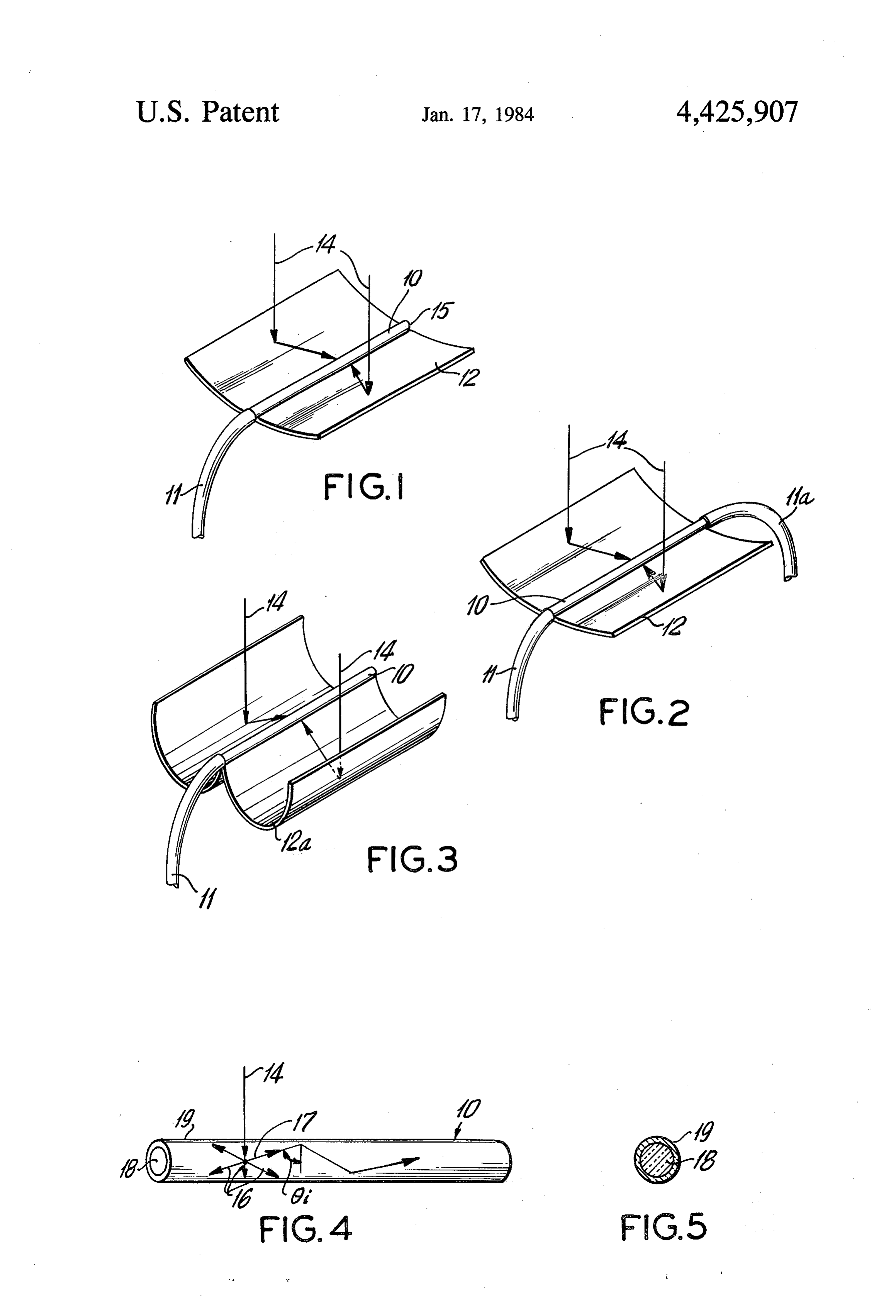
REFLECTOR-COUPLED FLUORESCENTSOLAR DESCRIPTION OF THE DRAWINGS COLLECTOR . . . .. . . . FIG.1 is a schematic illustration of one embodiment.
This is a continuation of application Ser. No. 190,666, FIG. 2 is a schematic illustration of yet another em filed Sept. 25, 1980, now abandoned. bodiment of the present invention. FIG. 3 is a schematic illustration of a particularly preferred embodiment of
FIELD OF THE INVENTION the present invention.
The present invention relates generally to solar col FIG. 4 is a geometrical diagram illustrating one of the lectors. More particularly the instant invention is con 10 principles of operation of the present invention. cerned with the collection of solar radiation over a FIG. 5 is a cross sectional diagram of an alternate form of a fluorescent fiber useful in the practice of this relatively large area, concentrating it and transmitting it invention.
to a point of use.
Background of the invention 15 detailed description of the
The economic conversion of solar radiant energy into INVENTION . electrical or thermal energy requires a relatively high of solar radiation and its 1,transmission Turning now to FIG. the system for the collection to a point of utili solar flux impinging on the conversion device. Conse quently, there have been numerous attempts to collect 20 zation according to the present invention includes a cylindrical fluorescent fiber 10 optically coupled at one the generally diffused sunlightfalling on relatively large end areas, concentrating it into a small area for more effi as thetoparabolic an optical wave guide 11. Reflector means such cient conversion of the radiant energy to a more useful ing solar radiationreflector. 12 is provided for concentrat (indicated by line 14) impinging over form of energy. In U.S. Pat. No. 4,114,592, for example, a generally wide area and reflecting there is disclosed a lense type device for collecting solar 25 to impinge on the fluorescent fiber the solar flux so as radiation over a relatively large area and focusing it light impinging on fluorescent fiber 10, As 10. a result of light is gener onto a relatively small area. Lense type devices suffer ated within the fiber and internally reflected and trans from the disadvantage that they are expensive and have mitted by optical wave guide 11 to a point of use. The aberrations that result in lower than optimum effi end 15 of the cylindrical fiber 10 is provided with a ciency. Another type of solar concentrator employs 30 mirrored surface so that any light which is transmitted mirrors such as a parabolic mirror for focusing the inci toward the distal end 15 of the cylindrical fluorescent dent solar radiation onto a thermal energy collector. fiber will be reflected back toward the optical wave U.S. Pat. No. 4,154,219 is exemplary of a system em guide. 11. . . . . . .. . . ploying a parabolic focusing device. These types of In operation then, incident solar radiation 14 imping devices suffer from thermal and reradiation losses. 35 ing over a relatively wide area is received by the para Another type of solar concentrating device consists bolic mirror 12 and reflected so as to impinge on the of a large area of fluorescent material on which solar fluorescent fiber 10 where the impinging light stimu radiation impinges and as a consequence thereof, the lates the emission of light of a different and longer wave fluorescent material emits radiation which is internally length than the solar radiation. This re-emitted light is reflected within the collector and directed toward a 40 internally reflected and transmitted through the cou smaller area where it is optically coupled, for example, pled optical wave guide 11 to a point of utilization. to a photovoltaic device. Examples of such devices are In the embodiment shown in FIG. 2, the cylindrical given in U.S. Pat. No. 4,149,902 and U.S. Pat. No. fluorescent fiber 10 is optically coupled at both its ends 4,188,238. Among the disadvantages of these devices 45 to optical wave guides designated generally as 11 and are the high costs of fluorescent materials and the geo 11a.
metric constraints in coupling the collector with an It should be appreciated that when using a parabolic energy converter. mirror, such as that shown in FIGS. 1 and 2, it is pre From the foregoing it is apparent there is a need for ferred to maintain the position of the reflector relative new and improved solar energy collection systems. 50 to the sun so that the reflected radiation impinges on the fluorescent fiber 10.
SUMMARY OF THE INVENTION In the particularly preferred embodiment of this in vention shown in FIG. 3, the fluorescent fiber 10 is
According to this invention, there is provided a sys optically tem for the collection of electromagnetic radiation and preferred coupled reflector to an optical wave guide 11. The means, however, is a compound the transmission of that radiation to a point of use. In its 55 parabolic reflector 12a.
simplest sense, an apparatus for the collection and trans 10 is positioned as closeAsasshown, the fluorescent fiber possible to the cusp of the mission of electromagnetic radiation comprises a cylin reflector. . drical fluorescent fiber, at least one end of which is optically coupled to an optical wave guide, and means reflector as shown in FIG. 3, eliminates the parabolic As will be appreciated, use of a compound need for for reflecting solar radiation impinging over a relatively 60 operating the system in a tracking mode and hence the wide area onto said cylindrical fluorescent fiber. Prefer device can be mounted in a permanent position. ably, a compound parabolic mirror is employed for A further explanation of the invention is now made reflecting incident solar radiation onto the optical fluo with particular reference to FIG. 4. As can be seen in rescent fiber. FIG. 4, incident solar radiation 14, which impinges on The precise characteristics and features of the inven 65 the fluorescent fiber 10, will be absorbed by the fluores tion will become more readily apparent in the following cent material and then re-emitted isotropically as longer detailed description when read in light of the accompa wavelength radiation, shown by arrows 16. When that nying drawings. radiation, exemplified by line 17, reaches the front of 4 the top surface of the cylindrical fiber 10, if it makes an cal wave guide is achieved; (c) solar radiation is trans angle, 6, greater than the critical angle, that radiation ported as light to the point of use; and, (d) the amount will be totally trapped and reflected within the optical of expensive fluorescent materials required is substan fiber 10 and transmitted toward the end thereof. The tially reduced, thereby lowering the solar receiver cost. critical angle, of course, refers to the largest value The invention has been described in detail with par which the angle of incident may have for a ray of light ticular reference to the preferred embodiments thereof, passing from a more dense medium to a less dense me but it will be understood that reasonable variations and dium. If the angle of incidence, 6, exceeds the critical modifications are possible without departing from the angle, the ray of light will not pass into the less dense spirit and scope of the invention. medium, but will be totally, internally reflected back 10 What is claimed is:
into the denser medium. 1. A device for the collection and transmission of Fluorescent fibers and the method of preparationare electromagnetic radiation comprising:
well-known. Indeed, fluorescent materials in the form a cylindrical fluorescent fiber formed from a light of liquids, plastics and glass have been fabricated into transparent fiber material on which has been ap fibers for numerous uses. In the practice of the present 15 plied at least one fluorescent sheet, said fluorescent invention, however, it is particularly preferred that the sheet being formed from a fluorescent dye incorpo fluorescent fiber 10 be a glass fiber which has been rated in a polymeric binder; impregnated with a suitable fluorescent inorganic oxide. reflector means for reflecting radiation impinging Eu2O3 and Sm2O3 are examples of suitable fluorescent over a relatively wide area so as to impinge on the materials for impregnating the glass fiber so as to render 20 circumference of said fluorescent fiber; it sufficiently active. Indeed, the cylindrical fiber collec at least one optical wave guide optically coupled to tor with its coupled optical wave guide can be conve one end of said fluorescent fiber whereby light niently prepared by taking the appropriate length of an impinging on said fluorescent fiber is internally optical wave guide and removing from a portion thereof the cladding which is present over the core 25 reflected and transmitted by said optical wave glass of the optical wave guide. Thereafter, the section guide to a point of use. of wave guide material which has its cladding removed, is a2.parabolic
The device of claim 1 wherein said reflector means reflector.
can be impregnated or doped with a suitable fluorescent 3. The device of claim 1 wherein said reflector means material, thereby providing an active cylindrical fluo rescent fiber optically coupled to an optical wave guide. 30 is a compound parabolic reflector. Optionally, the cylindrical fluorescent fiber 10 can be 4. The device of claim 2 or 3 wherein at least one optical wave guide is optically coupled at one end to formed, as illustrated in FIG. 5, from a light transparent each fiber material 18 on which has been applied at least one end of the fluorescent fiber. fluorescent sheet 19. The fluorescent sheet material 18 5. A solar energy collection and transmission device may be formed, for example, from a fluorescent dye 35 comprising:
incorporated in a polymeric binder. Such fabrication a cylindrical fluorescent fiber formed from a light techniques are well-known in the art. transparent fiber material on which has been ap In accordance with a particularly preferred embodi plied at least one fluorescent sheet, said fluorescent ment of the present invention, the fluorescent device of sheet being formed from a fluorescent dye incorpo the present invention comprises a fluorescent fiber, for 40 rated in a polymeric binder; example, having a diameter of about " and being ap compound parabolic reflector for focusing solar proximately six feet long, positioned within a com radiation incident on the circumference of said pound parabolic reflector with a concentration ratio of reflector onto said fluorescent fiber; two, providing an acceptance angle of 60. The accep at least one optical wave guide optically coupled to tance angle, of course, is defined by the midline of the 45 said fluorescent fiber whereby solar radiation im reflector to its edge. The cylindrical fluorescent fiber is pinging on said fluorescent fiber is internally re optically coupled to an optical wave guide so that light flected and directed toward said optical wave impinging upon the parabolic reflector would be redi guide for transmission therethrough to a point of rected toward the fluorescent fiber and the light emitted Sc.
therein would be internally reflected toward and 50 6. The device of claim 5 wherein the compound re through the optical wave guide, and thereby transmit flector has a cusp and said fluorescent fiber is positioned ted to a point of use. adjacent said cusp.
Among the advantages of the device of the present 7. The device of claim 6 wherein said device has an invention are the following: (a) high concentration ra angle of acceptance of about 60.
tios can be used; (b) simpler optical coupling to an opti 55 k k is k is
Provenance
- Collection
- Patents citing this work
- Pages
- 4
- Method
- pdftotext (the PDF's own text layer) + pdftoppm 300dpi page scans
- Patent office record
- patents.google.com →
- Source
- Google Patents citing-documents table
- Assignee
- Exxon Research And Engineering Co.
- Published
- 1984-01-17
- Transcribed from
- patentimages.storage.googleapis.com →