

patent · US4430304A
Slab reformer
7 February 1984
Text
Page 1bibliographic recordscan →
Spurrier et al.
54). SLAB REFORMER
75 Inventors: Francis R. Spurrier, Whitehall; Egon A. DeZubay, Mt. Lebanon;
Alexander P. Murray, Murrysville;
Edward J. Vidt, Churchill, all of Pa.
Assignee: The United States of America as represented by the United States
Department of Energy, Washington,
Int. Cl. .............................................. F28D 21/00 52 U.S. C. ........................................ 422/204; 48/61;
1,959,151 5/1934 Beekley ........................... 422/218 X
3,450,507 6/1969 Korwin ............................... 48/94 X 3,453,146 7/1969 Bawa et al. ....................... 48/105 X
3,541,729 11/1970 Dantowitz .............................. 48/94 3,607,125 9/1971 Kydd ............ ... 48/94 X 3,635,682 1/1972 Vine et al. .......................... 48/94 X
3,909,299 9/1975 Corrigan ............................. 48/94 X
3,980,440 9/1976 Morse et al. ........................ 48/94 X 4,071,330 1/1978 Sederquist .............................. 48/94 4,098,587 7/1978 Krar et al. ..... ... 48/94 4,098,588 7/1978 Buswell et al. ......................... 48/94 4,098,589 7/1978 Buswell et al. ......................... 48/94
4,203,950 5/1980 Sederquist .......................... 48/94 X
FOREIGN PATENT DOCUMENTS
OTHER PUBLICATIONS
Olesen et al., “The UTC Steam Reformer', UTC, Santa
Primary Examiner-Richard L. Chiesa
Attorney, Agent, or Firm-W. E. Otto; E. L. Levine
Slab-shaped high efficiency catalytic reformer configu rations particularly useful for generation of fuels to be used in fuel cell based generation systems. A plurality of structures forming a generally rectangular peripheral envelope are spaced about one another to form annular regions, an interior annular region containing a catalytic bed and being regeneratively heated on one side by a hot comubstion gas and on the other side by the gaseous products of the reformation. An integrally mounted combustor is cooled by impingement of incoming oxi dant.
12 Claims, 14 Drawing Figures
Drawings
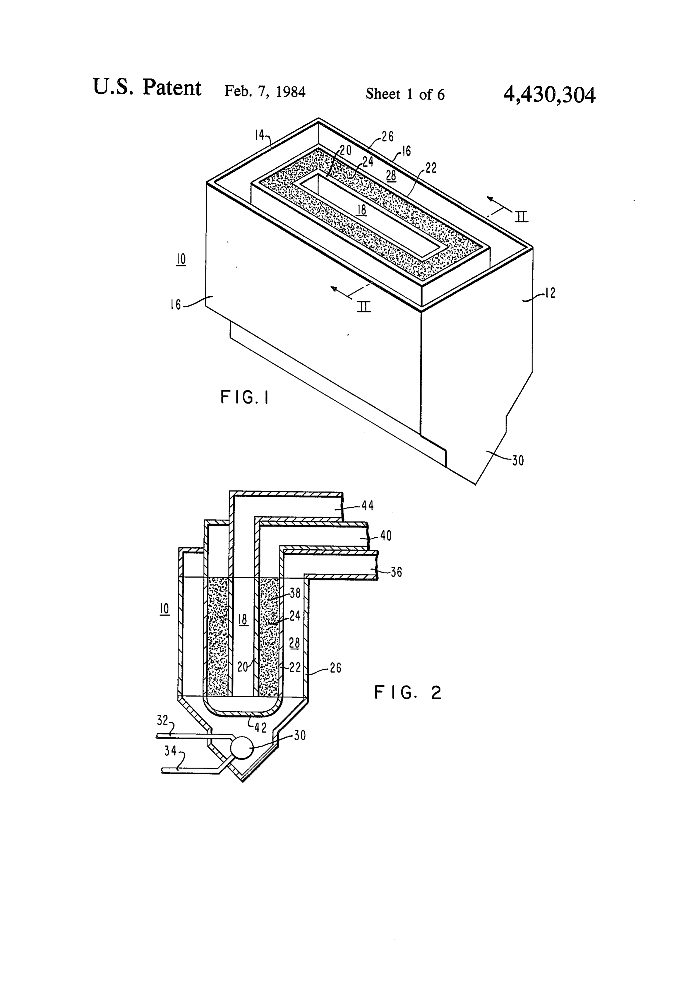
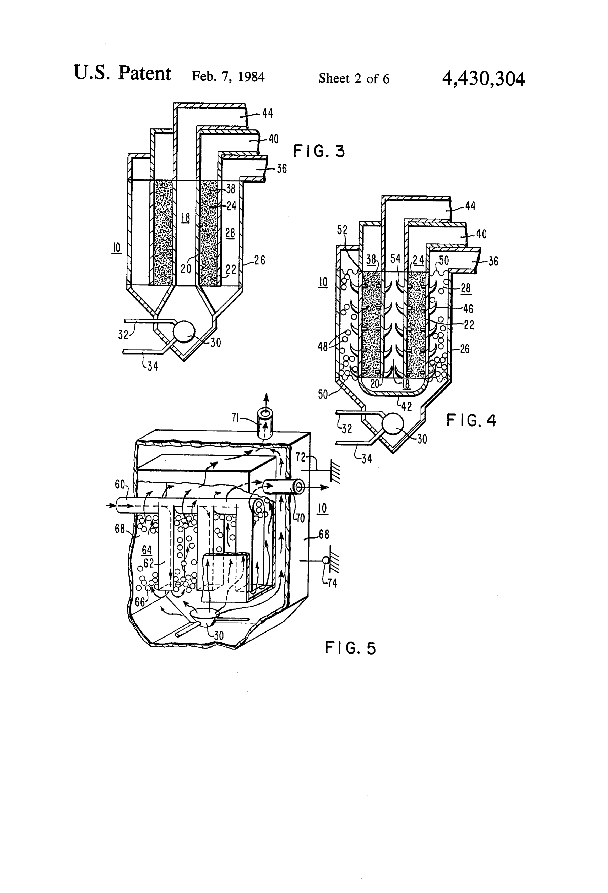
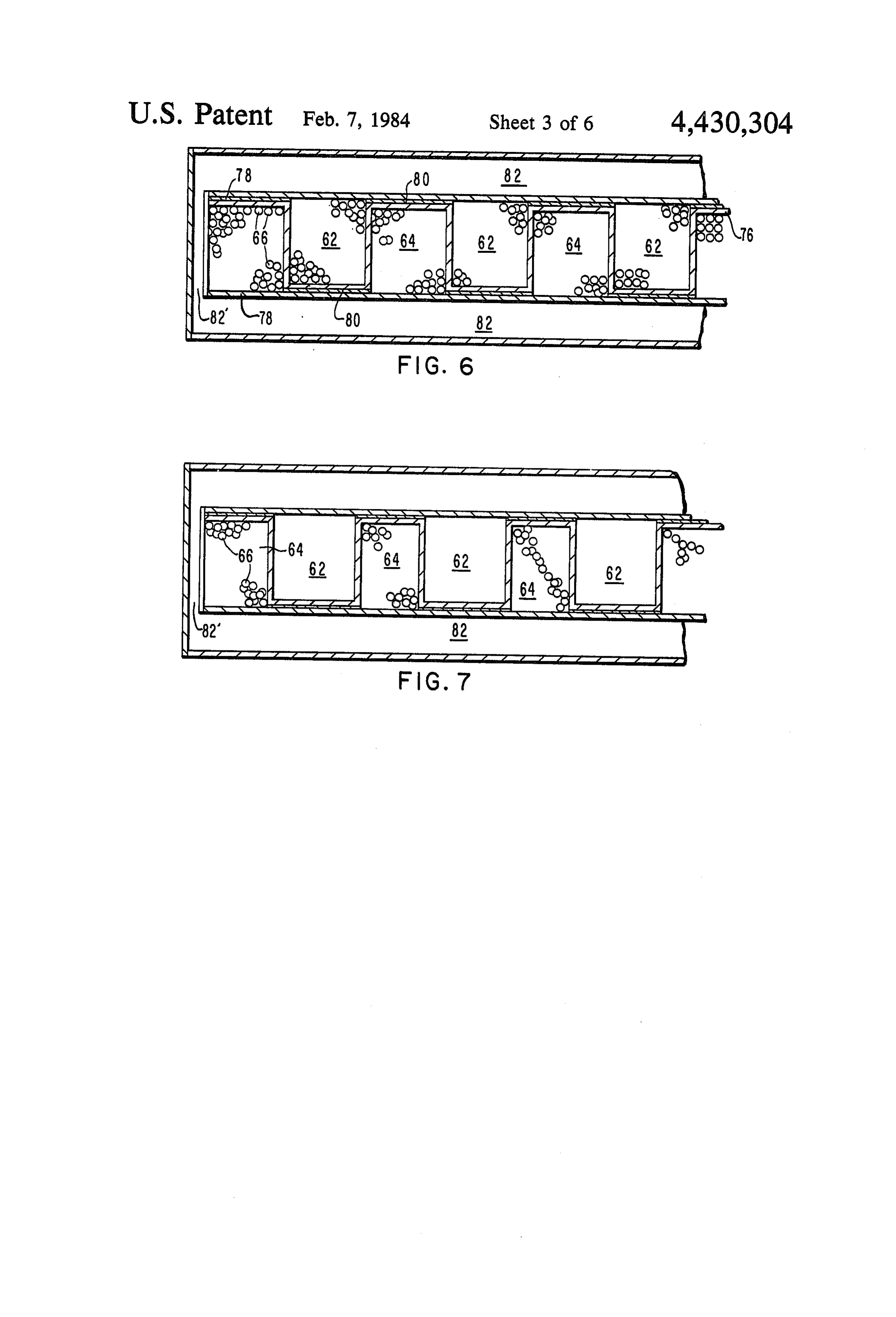
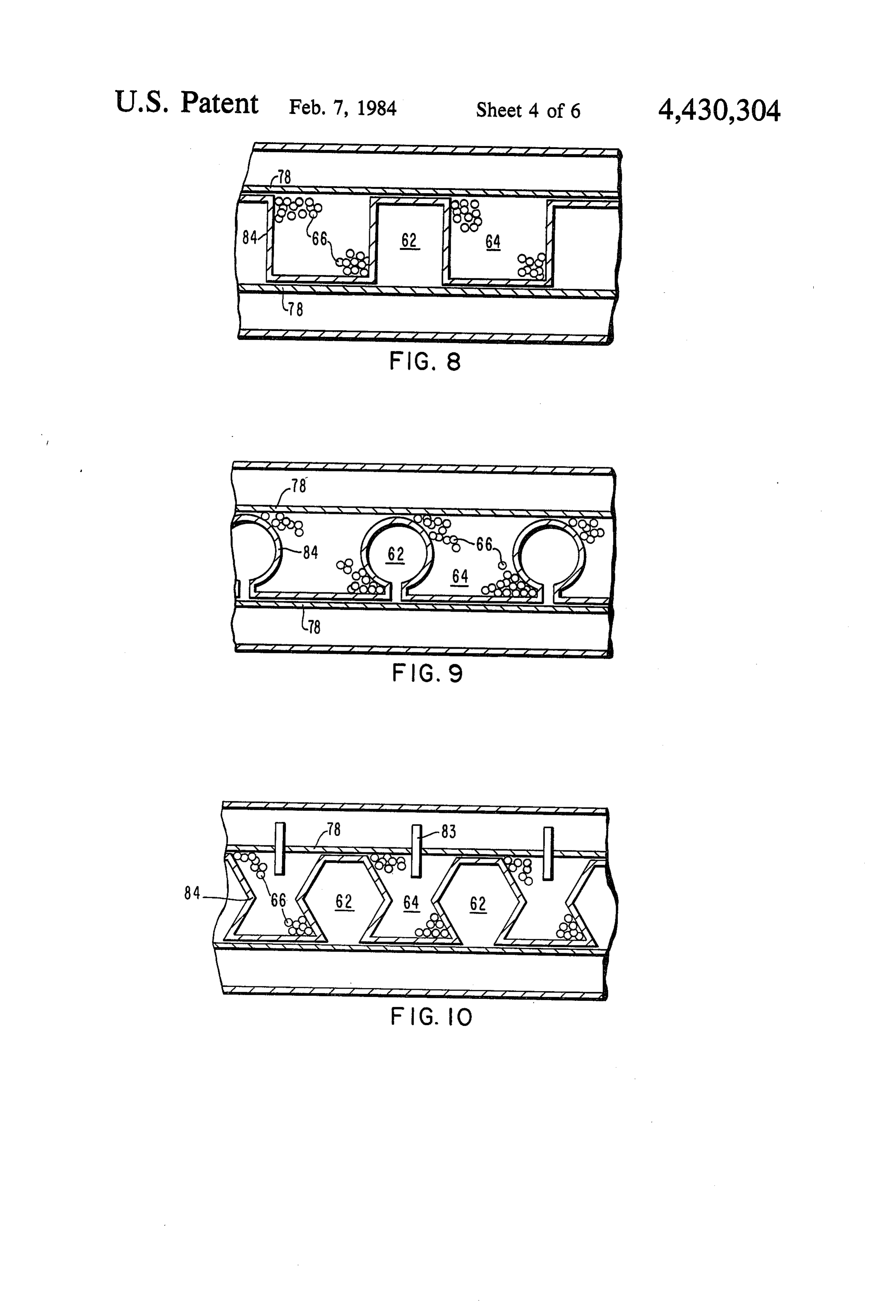
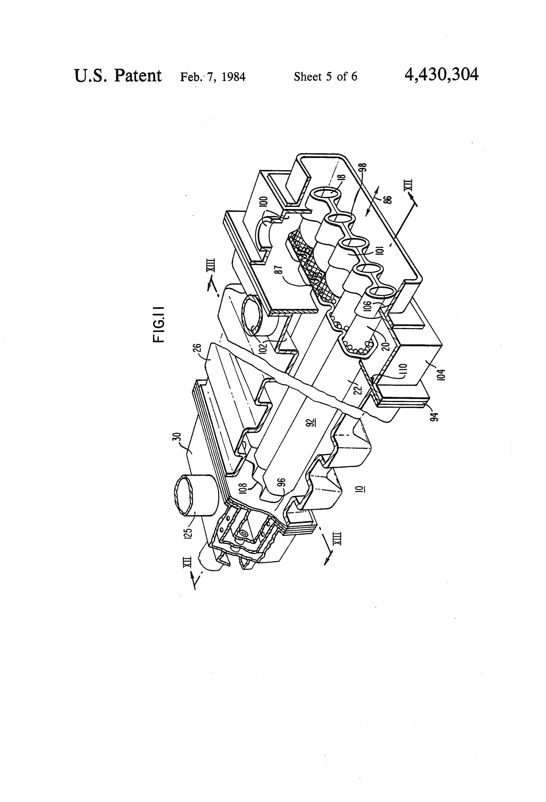
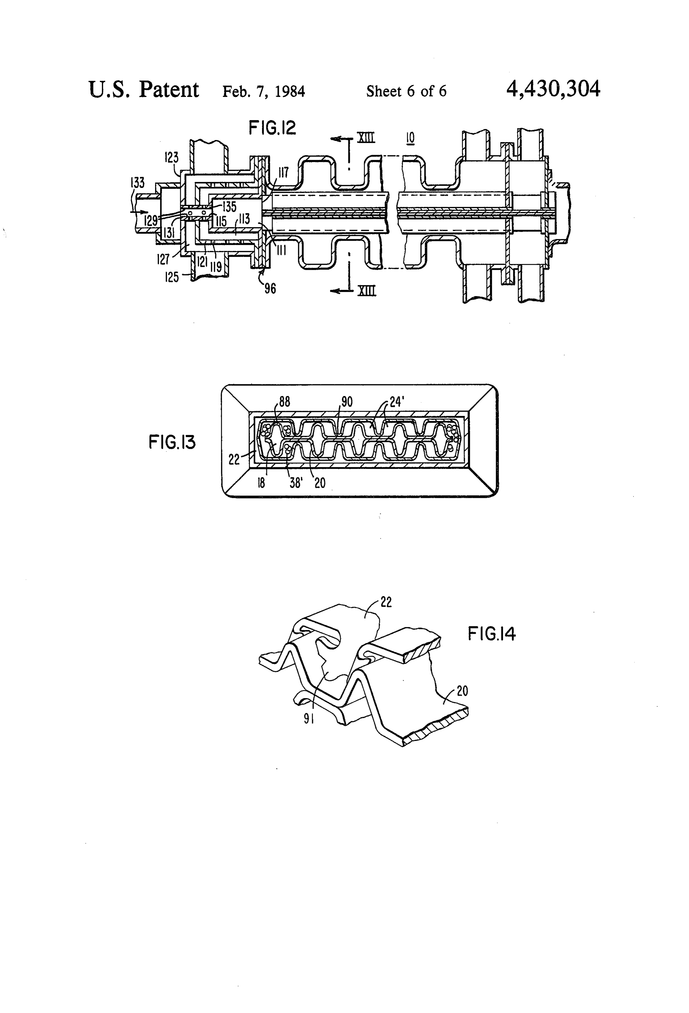
FIG. 5 is a schematic perspective view, partially in from two distinct regenerative sources, the combustion section, of another embodiment reformer; gas and the product gas.
Page 2drawing sheetscan →
Page 3drawing sheetscan →
Page 4drawing sheetscan →
Page 5drawing sheetscan →
Page 6drawing sheetscan →
Page 7drawing sheetscan →
Page 8scan →
for utilization in fuel cell based power generation sys
Government contract summary of the invention
The invention disclosed herein was made or con 5 This invention provides efficient catalytic reformers, ceived in the course of or under contractual agreements and particularly reformer configurations, useful in the with the U.S. Government identified as Nos. DE-AC provision of fuels such as hydrogen and carbon monox 03-78-E-11300 (DOE) and DEN3-161 (NASA). ide for fuel cell based systems. As opposed to the tubu lar configurations of the prior art, the reformers are
BACKGROUND OF THE INVENTION O based on a so-called flat slab geometry. For descriptive 1. Field of the Invention purposes, and in its most general form, a preferred em This invention relates to catalytic gas reformers use bodiment cluded are is generally rectangular in cross section. In three elongated ducts of rectangular cross ful to convert a reformable medium to a usable fuel, and section having parallel sides with the rectangular struc more particularly provides reformers of novel non 15 tures oriented with tubular geometries useful to convert mediums such as chamber bounded common externally axes. This forms a central by an annular region hydrocarbons to fuels such as hydrogen and carbon which contains a catalytic material, and which is in turn monoxide for use in fuel cell based systems. bounded by an annular passage. In one embodiment a 2. Description of the Prior Art reformable gaseous medium, such as a mixture of meth Reformers are used throughout process industries to 20 ane produce a fuel, such as a hydrogen rich stream, by cata lyticand steam, flows in one direction through the cata lytically reacting steam and a hydrocarbon at high tem 180, annular region, is reformed to a useful fuel, turns peratures, typically above 1,000 F. The reforming re chamber. A hotcounter-directional actions are highly endothermic. The hydrogen is usu bustion reaction,gas, preferably the product of a com flows through the outer annular pas ally consumed on sight by any of several processes, for 25 sage in the same direction as the reformed product gases example, ammonia synthesis, de-aromatization, and and, accordingly, counter-directional to the input meth hydrodesulfurization. In many cases, methane is used as ane and steam mixture. A similar structural the hydrocarbon. Large, industrial steam/methane re ment can also be utilized where the methane arrange mixture former systems operate at 10 to 20 atmospheres of pres again flows through the catalytic annular region, but sure and high gas temperatures in the range of 1500 to 30 where the product fuel flows through the outer annular 2000' F. These operating conditions have been carried passage and the combustion gas flows through the cen out through a tubular design, primarily for stress and tral chamber. The counter-directional flow relation, strength considerations. Catalytic bed volume in these that is, with the gas in the central chamber and annular units typically has considerable excess capacity, on the passage flowing in a common direction and the gas in order of 50%. Hence, reformer tube dimensions of up to 35 the intermediate annular region flowing counter-direc 6 inches in diameter by 30 to 50 feet long are common tional through a catalytic bed, is maintained. in refinery operations. Other embodiments advantageously used corrugated Furthermore, unit thermal efficiency of the large or convoluted structures. In one preferred form a corru industrial reformers is low, but the actual overall system gated shell forms plural chambers which together form efficiency is substantially higher as the waste heat and an outer envelope approximating a rectangular cross undesired products.are often utilized by other site pro sectional configuration. This configuration can also be CSSS. described as a corrugated rectangular structure. Sur A stand-alone reformer, producing hydrogen for a rounding each chamber are regions, formed within a fuel cell based generation system, should preferably corrugated duct, containing catalytic material, the outer achieve higher unit efficiencies. Therefore, increasing 45 envelope of the totality of which also approaches a slab heat transfer and hydrogen production while decreas or rectangular configuration. These structures are inte ing waste heat, size, and undesirable byproducts be grated into a module, which is affixed at one end to a comes of high importance. corrugated casing and free to slidably expand within the A high efficiency tubular design has been presented, casing. The casing includes corrugations preferably at and is described in a paper presented by O. L. Oleson et SO 90 to the corrugations of the shell and duct. Gases from al, October, 1979, entitled “The UTC Steam Re a combustion reaction in a combustor which is cooled former'. Similar reformer designs are described in U.S. by impingement of incoming oxidant, flow through the Pat. Nos. 4,071,330, 4,098,587, 4,098,588, 4,098,589, and inner chambers.
4,203,950, issued to United Technologies Corporation.
The designs all include regenerative heat exchange for 55 BRIEF DESCRIPTION OF THE DRAWINGS thermal efficiency, and a tubular arrangement. While The advantages, nature and additional features of the designs of this type will perform admirably, improve invention will become more apparent from the follow ments can be made. Units which are lower in cost and ing description taken in connection with the accompa easier to fabricate and assemble are desirable. Addition nying drawing in which:
ally, reformers having configurations more compatible FIG. 1 is a schematic perspective view of a simplified with the addition of fins, pins, or other heat transfer reformer in accordance with the invention; augmentation means are more attractive. And, reform FIG. 2 is a sectional elevation view taken at II-II of ers offering higher heat transfer area per unit bed vol FIG. 1, particularly showing flow paths of the various ume will increase efficiency. gaseous mediums;
It is thus desirable to provide reformers which offer 65 FIG. 3 is a view, similar to FIG. 2, showing alterna advantages in these areas. It is particularly beneficial to tive flow paths;
provide efficient catalytic reformers useful in the prepa FIG. 4 is a view, similar to FIGS. 1 and 2, schemati ration of fuels such as hydrogen and carbon monoxide cally showing additional structural features;
Page 9scan →
FIG. 5 is a schematic perspective view, partially in from two distinct regenerative sources, the combustion section, of another embodiment reformer; gas and the product gas.
FIGS. 6 and 7 are cross-sectional views of alternative The structural embodiment of FIG. 3 utilizes a me embodiments of the reformer of FIG. 5; chanical configuration similar to that of FIG. 2, includ FIGS. 8, 9 and 10 are yet other cross-sectional views 5 ing a chamber 18 within a shell 20, a catalytic bed 38 of alternate reformer embodiments for the structure of retained in an annular region 24 between the shell 20 FIG. 5; and a duct 22, and an annular passage 28 between the FiG. 11 is a perspective view, partially in section, of duct 22 and a casing 26. Also provided is a combustor another reformer embodiment; 30. Here, however, the hot combustion gas discharged FIG. 12 is an elevational section view taken at XII 10 from the combustor 30 flows through the central cham -XII of FIG. 11; ber 18. The reformable medium flows through the cata FIG. 13 is an elevational section view taken at XIII lytic bed 38, is turned, and flows through the annular -XIII of FIG. 11, with some detail omitted for clarity; passage 28. The high surface area catalytic bed and and regenerative thermal interexchange are maintained. FIG. 14 is a perspective view of a portion of another 15 In either configuration, the rectangular arrangement embodiment of a reformer in accordance with the in is readily compatible with the addition of means for vention. augmenting heat transfer among the flow paths and mediums. FIG. 4 shows the inclusion of fine 46 and
DESCRIPTION OF THE PREFERRED alumina balls 48 within the combustion gas annular EMBODIMENTS 20 passage 28. The balls 48 are maintained within the pas Referring now to FIGS. 1 and 2 there is shown a sage 28 through use of mesh screens 50. The screens 50 reformer 10. The reformer in accordance with the in are preferably metallic, and can also comprise refrac vention is referred to as a slab, or flat slab, or hollow tory ceramic materials. Also shown are pins 52 extend slab, since it is comprised of components having at least ing into the catalytic bed 38. Fins 54 are also disposed two edges 12, 14 which are shorter than a third side 16, 25 within the product gas chamber 18. as opposed, for example, to a circular cross-section or Referring now to FIGS. 5-10, and initially FIG. 5, tubular geometry. The edges and sides need not be flat. additional slab reformer 10 configurations are shown. A The reformer includes one or more chambers 18 formed reformable medium, such as a mixture of methane and within a shell 20. The shell 20 can be comprised of steam, enters an inlet manifold 60 which is preferably multiple interconnected pieces. Laterally surrounding 30 tubular. The medium then passes in parallel through a at least a significant portion of the axial length (the plurality of inlet channels 62, is turned 180, and flows vertical direction in FIGS. 1 and 2) of the shell 20 is a through outlet channels 64, which retain catalytic beds duct 22. The duct 22 is spaced from the shell 20 so as to 66. The hot combustion gas discharged from the com form an annular region 24, or a plurality of regions 24 bustor 30 flows across the channels 62,64 (above and as discussed particularly with respect to FIG. 13, be 35 below the plane of the paper in FIG. 5), and can also tween the duct 22 and shell 20. Laterally surrounding at flow about the sides 68 of the outer outlet channels 64 least a significant portion of the axial length of the duct before being discharged through an outlet manifold 71. 22 is a casing 26. The casing 26 is spaced from the duct The reformed products are discharged through an out 22 so as to form an annular passage 28 therebetween. A let manifold 70. For purposes of controlling thermal catalytic material is retained in the annular region 24 to expansion, one end of the channel structures or the form a catalytic bed 38. structures immediately surrounding the channels is A combustor 30 is preferably associated and integral preferably fixed, shown as support 72, and the other end with the reformer 10. A combustible fuel, such as natu is free to slide, as shown by rolling support 74. ral gas or methane, enters the combustor 30 through a Although other configurations are possible, it is pre conduit 32, and an oxidant, such as air, enters the com 45 ferred that the channels 62, 64 have a generally U bustor through another conduit 34. In the embodiment shaped or rectangular cross-section. FIG. 6 shows a shown best in FIG. 2, the hot combustion gas flows generally square cross-section wherein a catalytic bed from the combustor 30 to and through the annular pas 66 is contained within both the inlet channels 62 and sage 28, and is discharged through an outlet 36. A re outlet channels 64. A corrugated sheet 76 sandwiched formable medium, such as a gaseous mixture of methane 50 between two plates 78 can be utilized to fabricate the and steam, enters the catalytic bed 38 retained within structure. To achieve good thermal bonding, brazing 80 the annular region 24 from an inlet 40. The reformable can be utilized at selected locations, or along the entire mixture flows through the bed 38 in a path which is length of the channels 62, 64. FIG. 7 shows similar generally parallel and counter-directional to the con structure wherein the channels 62 and 64 are of differ bustion gas. During passage through the bed 38 refor 55 ing area, and catalytic material 66 is incorporated solely mation to a product gas, such as one comprising hydro in the outlet channels 64. Hot combustion gases flow in gen, carbon monoxide, some unreformed methane, and the interior sections 82. The side section 82 can be other reaction product constituents, takes place. The eliminated if desired.
reformed product gas then contacts a deflector 42, is FIGS. 8-10 show alternative cross-sectional configu turned 180°, and flows into and through the central rations for the inlet 62 and outlet 64 channels, and the chamber 18. The deflector 42 also functions as an insu catalytic beds 66. FIG. 8 shows a corrugated or “U” lating cap to protect the ends of the shell and duct from channel, FIG. 9 shows circular inlet channels 62, and the high temperatures at the combustor 30. The re FIG. 10 shows hexagonal inlet channels 62. Other con formed product gas flows counter-directional to the figurations are equally possible. FIG. 10 additionally unreformed inlet gaseous mixture, and is discharged 65 shows fins 83 extending from the catalytic beds 66 into through an outlet 44. It will be apparent that this config the interior section 82 to increase heat transfer into the uration and flow path provides a large surface area beds. These figures also show a slight spacing between catalytic bed and heat energy to the catalytic bed 38 walls 84 forming the channels 62, 64, and the plates 78 10 between which the channels are formed. This allows lateral bending stiffness and strength to withstand inter the walls 84 to float freely due to thermal expansion. nal pressures. Additionally, differential thermal growth Although not shown in FIGS. 8-10 for clarity, the which will occur between the shell 20 and the casing 26 walls 84 are affixed, thorugh means such as brazing or is accommodated by local bending of the corrugated welding, at one location along their axial length. casing 26, as in a bellows. The duct 22, being fixed at Referring now to FIGS. 11-14 there is shown in one end only, is free to slidingly move with respect to more detail reformer structures in accordance with the the casing. Strength and stiffness in the axial direction invention. The structure shown retains the basic flat are provided by the shell 20.
slab arrangement, and provides highly efficient thermal When welds 98 and 110 are cut for removal of the interexchange among the various mediums and high 10 manifold 100, the partition 104 is removable with the efficiency reformation capability. For descriptive pur corrugated sleeve 101 which remains attached thereto poses the reformer 10 is described from the central area through weld 106. This allows access to the catalytic outward. As shown best in FIGS. 11 and 13, a corru bed.
gated shell 20 forms therein a plurality of chambers 18.
An envelope defined about the periphery of the plural 15 torAffixed to the opposite side of plate 96 is the combus 30. A combustion reaction occurs in a combustion ity of chambers approaches a generally elongated box in chamber 111 formed within a liner 113 having an inlet the axial direction of rectangular cross-section. A corru 115 and outlet 117. The outlet 117 communicates di gated duct 22 surrounds at least a substantial portion of rectly with the chambers 18 within the corrugated shell the axial length of the shell 20. The axial direction is 20. The liner 113 is cooled by impingement of multiple indicated by the arrow identified by reference numeral 20 86. While the reformer can be substantially symmetrical jets of an oxident, such as air, flowing through holes 119 about an axis in the axial direction, it need not be so entersbaffle in a 121 disposed about the liner 113. The air structured. The envelope formed about the periphery of one oramore frame 123 disposed about the baffle 121 through inlets 125. Upon entering a flow annulus the corrugated duct 22 also approaches a rectangular 127 disposed between slab. The duct 22 is spaced from the shell 20 so as to 25 flow splits such that athe frame 123 and baffle 121, the form a plurality of regions 24. The duct 22 and shell 20 impingement holes 119 and portion first flows through the a second portion flows to preferably contact one another, such as at locations 88 openings 129 in one or more mixing tubes 131. A com and 90. These contacts can be fixed through fasteners, bustible welds or other affixing means, at one lateral location or fuel enters each mixing tube 131 through an along their common axial lengths. Preferably, however, 30 inlet 133. The openings 129 in each mixing tube 131 there is merely a sliding support between these mem flame allow premixing of the air and fuel prior to entering the bers to allow for thermal expansion. zone within the liner 113. Within the chambers 24' are catalytic beds 38. The The mixing tube 131 is welded to the frame 123, and beds 38' are preferably comprised of particulates or is free to slidably expand through supports in the liner pellets to provide a large surface area, and are retained 35 113 and baffle 121. If desired, additional air and fuel in place by a refractory metal or ceramic gauze 87 at the mixing or local cooling can be accommodated through end of duct 22. The gauze is lightly tack-welded to duct additional openings in the liner 113, such as openings 22 or otherwise made readily removable to facilitate 135.
catalyst replacement. A bent tab 91 is utilized at the Since numerous changes may be made in the above other end of the duct 22 as shown in FIG. 14. The tabs 40 described apparatus without departing from the spirit 91 are particularly beneficial in enhancing the cooling and scope thereof, it is intended that all matter con of a plate 96 at the end of the duct 22 where the gases tained in this disclosure be interpreted as illustrative, and change flow direction. The duct-shell-catalyst structure not in a limiting sense.
described forms a module 92. We claim:
At least a substantial portion of the axial length of the 45 1. A catalytic reformer comprising: module 92 is contained within a corrugated casing 26. a hollow elongated flat non-circular slab; The corrugations of the casing 26 preferably are ori a duct disposed horizontally within said slab and ented at an angle to the corrugations of the duct 22 and extending along a longitudinal axis of said slab, said shell 20, and desirably are orthogonal thereto. The en duct forming a first annular region between said velope formed by the casing 26 also approaches a slab 50 slab and said duct;
or rectangular configuration. The casing and associated a shell disposed within said duct forming a second components form a sealed structure about the enclosed annular region between said duct and said shell; portion of the module 92. The casing 26 is welded to a a bed of catalytic material disposed within said sec separator plate 94 at one end, and to plate 96 at the other ond annular region within said slab; end. The separator plate 94 is welded or otherwise 55 means for flowing a reformable gaseous medium sealingly affixed to the duct 22. through said bed; and
The separator plate 94 separates a reformable me means for heating said bed from within said slab. dium inlet manifold 100 from a product gas outlet mani 2. A catalytic reformer comprising: fold 102. Also sealingly affixed to the separator plate 94 an elongated corrugated shell forming therein an by a weld 110 is a partition 104 which is sealingly af. 60 elongated chamber;
fixed through fastening means such as a weld 106 to the an elongated corrugated duct spaced about at least a corrugated sleeve 101. The corrugated sleeve is at portion of said shell so as to form an annular region tached, in turn, to the shell 20 by means of a weld 98. therebetween, the corrugations of said duct being Weld 98 is then accessible for grinding to release mani generally aligned with the corrugations of said fold 100 from shell 20, preparatory to catalyst replace 65 shell;
ment. The shell 20 is also affixed at its opposite end to a catalyst disposed within said annular region; the plate 96, through fastening means such as a weld an elongated corrugated casing spaced about at least 108. In this manner, the corrugated casing 26 provides a portion of said duct, the corrugations of said 11 casing being oriented at an angle with respect to the corrugations of said shell and duct;
means for creating a hot gaseous stream;
means for flowing said hot gaseous stream in a first direction through said elongated chamber; and means for flowing a reformable gaseous medium through said annular region counter-directional to said first direction and for flowing the product gas from said annular region between said duct and 10 casing in said first direction.
3. The reformer of claim 2 wherein said means for creating a hot gaseous stream comprise a liner forming therein a combustion zone, a conduit for conducting a combustible fuel into said combustion zone, a conduit for transporting an oxidant, and a baffle for impinging 15 said oxidant from said oxidant conduit onto the exterior of said liner and then directing said oxidant into said combustion zone.
4. The reformer of claim 3 further comprising a frame 20 spaced about at least a portion of said baffle, said frame being oriented to direct a first portion of said oxidant through said baffle and to direct a second portion of said oxidant into said fuel upstream of said combustion zone. 5. The reformer of claim 4 wherein said shell, duct, 25 casing, liner, baffle and frame consist of metal. 6. The reformer of claim 2 wherein said catalyst com prises particulate solids and further comrising means for retaining said catalyst within said annular region. 7. The reformer of claim 6 wherein said retaining 30 means comprise a gas permeable mesh extending be tween said shell and duct.
8. The reformer of claim 6 wherein said retaining means comprise a bent tab extending from an end of said duct across a portion of said annular region. 35 9. The reformer of claim 2 wherein said shell, duct, and casing consist of metal.
10. The reformer of claim 2 wherein said duct is fixedly mounted to said casing at an end of said duct, and the balance of said duct is slidably supported within 40 said casing.
11. A catalytic reformer having a catalyst-containing dule comprising:
said module including:
an elongated corrugated shell forming a plurality of combustion gas chambers therein;
an elongated corrugated duct spaced about at least a portion of said shell, and forming a plurality of regions therebetween, the corrugations of said duct being parallel to the corrugations of said shell; and a catalyst bed retained within said annular regions; a convoluted casing spaced about a portion of said duct and removably mounted at one end to said duct, the corrugations of said casing being angled with respect to the corrugations of said duct and shell;
means for flowing a hot gas through said chambers; and means for flowing a reformable gaseous medium through said catalyst bed.
12. A catalytic reformer comrising:
a plurality of axially elongated generally oval-shaped mechanically interconnected parallel shells, each said shell forming therein a chamber;
a plurality of axially elongated generally rectangu larly shaped mechanically interconnected parallel ducts, each said duct radially surrounding at least a portion of a corresponding, parallel chamber, each said shell and duct being partially spaced from one another and in contact with one another at each of their two shorter sides, forming between each said shell and duct a plurality of regions;
a catalytic bed retained within each said region; a sealed casing enclosing at least a portion of each said duct;
means for flowing a hot gas through said chambers; and means for flowing a reformable gas through said catalytic beds counter-directional to the flow of said hot gas. k e s :k k
Provenance
- Collection
- Patents citing this work
- Pages
- 11
- Method
- pdftotext (the PDF's own text layer) + pdftoppm 300dpi page scans
- Patent office record
- patents.google.com →
- Source
- Google Patents citing-documents table
- Assignee
- The United States Of America As Represented By The United States Department Of Energy
- Published
- 1984-02-07
- Transcribed from
- patentimages.storage.googleapis.com →