

patent · US4434026A
Acid concentrating and recovery system
28 February 1984
Text
Page 1scan →
United States Patent (19)
Harris
54 acid concentrating and recovery
System
76 Inventor: Mack Harris, 4608 W. 25th St., Little
52 u.s.c. .................................. 159/1 s; 159/28 c;
2,241,209 5/1941 Lea .................................... 159/28 3,333,019 7/1967 Nathan et al. ... ... 159/DIG. 19 3,351,538 11/1967 Andrassy ............................. 159/1 S 3,420,745 1/1969 Schlueter ............................. 159/1 S 3,743,484 7/1973 Morimoto ... 159/DIG. 19 3,929, 22 12/1975 Alkasab ............................... 159/1 S 3,969,214 7/1976 Harris.................................. 204/275 3,970,511 7/1976 Rat et al. ..... ... 159/DIG. 19
Sss nynynyn
as Sas
HaNaege at
N Crea N 27, 27.7 27te 27t
Msyynnn nav s v v n m s v
4,338,922 7/1982 Moore ................................. 159/1 S Primary Examiner-Bradley Garris
Attorney, Agent, or Firm-James A. Wong
System for concentrating and recovering acid compris ing in combination a receptacle or storage tank for receiving and containing weak or dilute acid; an evapo rating pan including a pipe connected to the receptacle or storage tank and a pump whereby acid may be deliv ered to the evaporating pan; a second receptacle or storage tank including a pipe connected to the evaporat ing pan and a pump whereby concentrated acid may be delivered to the second receptacle or storage tank; and an air drier device in the form of a tank containing acid and including an inlet through which air and water vapor may be introduced, and a pipe connection to the tank for weak or dilute acid; wherein the evaporating pan includes a heat collecting surface as a floor thereof and a lens focus top whereby heat energy from the sun's rays will heat and concentrate the acid therein by devel oping water vapor which is removed with air.
7 Claims, 7 Drawing Figures
Drawings
Page 2drawing sheetscan →
Page 3drawing sheetscan →
Page 4drawing sheetscan →
Page 5scan →
when such acid becomes too diluted or weak for gener
ACID CONCENTRATING AND RECOVERY ating heat or electricity. Air drier E and tank 1 are SYSTEM connected to each other by piping provided with an electrically operated valve N and a pump R, which is
FIELD OF THE INVENTION operated to pump acid from air drier E when the con The disclosed invention relates to a system compris through centration of such acid drops to about 85%, to tank 1 ing a component, such as a battery, using acid and an effected ina cap. An initial concentration stage may be tank 1 by passage of atmospheric air drawn apparatus for concentrating and recovering acid for storage and/or further use. by a blower T through metal tubes passing through tank 10 1 in heat exchange relationship with acid 4 to warm up
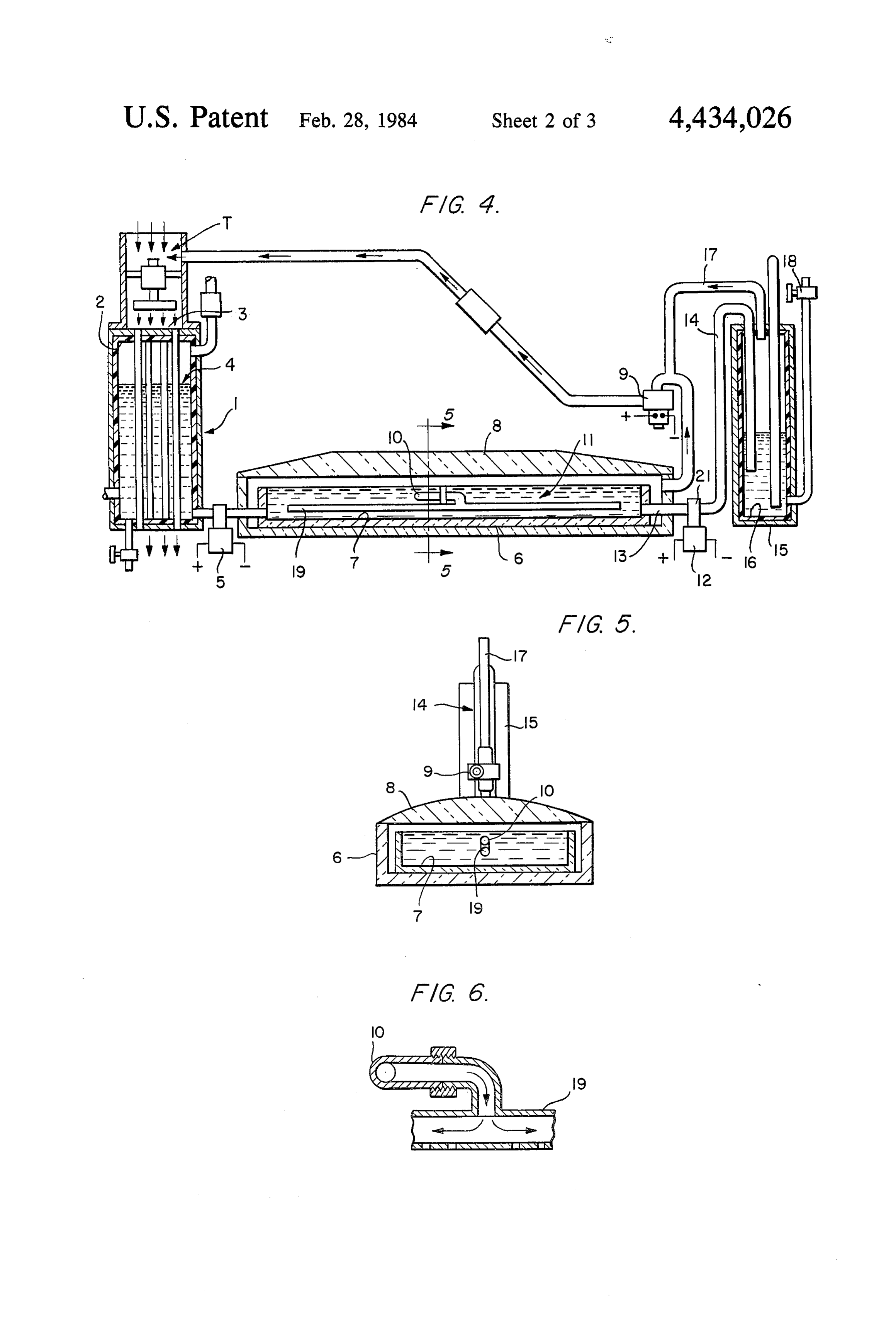
SUMMARY OF THE INVENTION acid 4. The metal tubes passing through tank 1 may be It is an object of the disclosed invention to provide a packed with fins to enhance its heat exchange function. new and improved apparatus for concentrating and The dilute acid 4 is pumped by pump 5 into evaporating recovering acid for storage or for use, as may be de 15 pan 6 through an interconnecting pipe section for fur sired, in devices such as batteries, which have need for ther concentration. Operation of pump 5 is controlled acid. by a float switch 20, shown in FIG. 7, when acid intro Another object of the disclosed invention is to pro duced into pan 6 reaches a predetermined level. Evapo vide a new and improved apparatus for converting and rating pan 6 is provided with a black lining 7 of Teflon storing naturally available energy from the sun or wind 20 or like material on the botton and/or side. Reconcen for use at night or during periods of tranquility. tration of the acid brought into pan 6 is achieved by It is also an object of the disclosed invention to pro evaporating the water content in the acid by solar en vide a new and improved apparatus for storing solar ergy developed by the sun's rays being concentrated energy during summer seasons for use during winter and focused by lens focus top 8 onto black Teflon lining SeaSOS. 7. As may be seen in FIG.4, lens focus top 8 is disposed It is further an object of the disclosed invention to 25 over pan 6. As lining 7 is heated from the sun's rays, the provide a new and improved portable apparatus by air and water vapor which is developed are removed which heat energy in the air may be used to reconcen from pan 6 by a suction or vacuum fan 9 leaving a con trate an acid and to generate electricity. centrated acid 11 in pan 6. When the acid 11 in pan 6 It is, moreover, an object of the disclosed invention to 30 reaches a concentration of about 92%, a pump 12 for provide a new and improved apparatus including an air discharging the acid 11 is turned on by a gravity control drier device in which air heated by the sun or by ex switch 21 to draw acid 11 through a suction pipe 13 and haust heat may be used to concentrate acid by evaporat through a discharge pipe 14 and into a storage tank 15. ing and removing water therefrom. To augment the concentration of acid in pan 6, hot SUMMARY OF THE DRAWINGS 35 exhaust air from ion tank, shown in FIGS. 2 and 3, may Illustrative of the disclosed invention the appended be tube brought into pan 6 through pipe 10 connected to a 19 having small outlet holes in the bottom through drawings represent in:
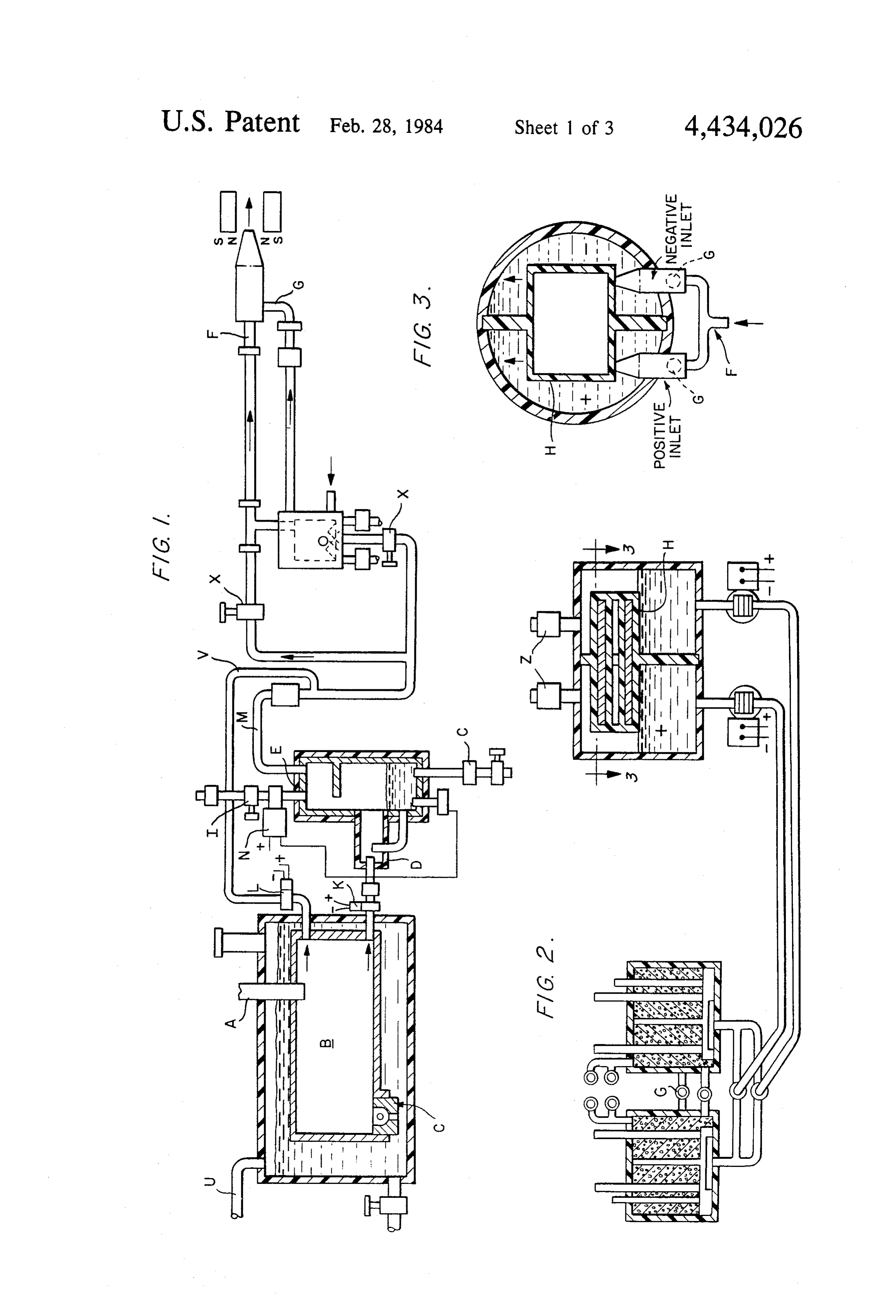
FIG. 1, an elevational, partially cross-sectional side which solution hot dry air passes into contact with the acid and accelerates evaporation of the water con view of an air storage tank in a water case with air drier tent. When the concentration of the acid reaches a level (E) connected to ion separating devices; of about 92%, pump 12 is turned on by gravity control FIG. 2, an elevational, cross-sectional view of an ion tank, with ions separated therein, the tank being con switch and the acid 11 is pumped to concentrated acid storage tank 15. On the other hand, when the concen nected by outlet pipes and pumps to electric and gas tration of the acid 11 in pan 6 is diluted to about 90% by generating cells;
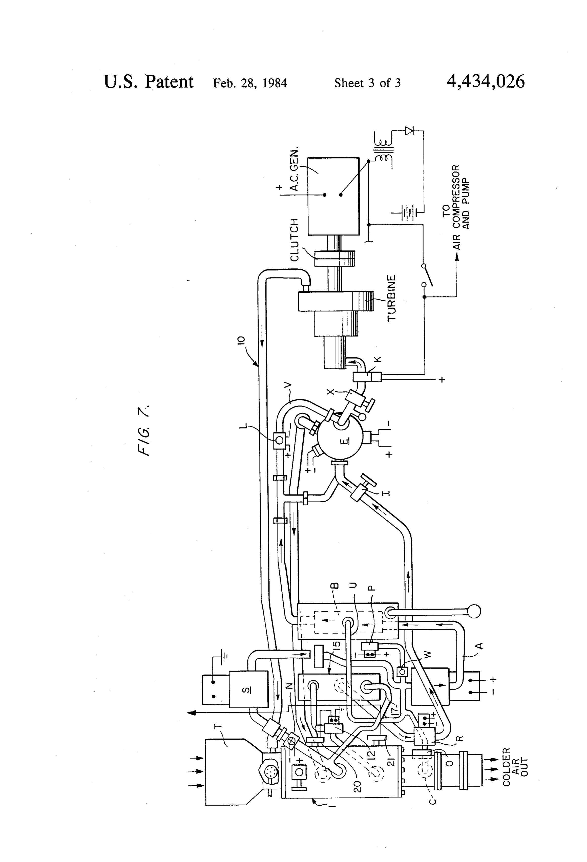
FIG. 3, a cross-sectional, top view of the ion tank 45 pump addition of weakened acid from tank 1, for example, taken on the line 3-3 of the FIG. 2; 12 is kept in the off condition by switch 21, since FIG. 4, an elevational, cross-sectional view of an acid acid of a concentration of about 90% is too weak for reconcentrating device; use, as desired, and for storage in tank 15. A plastic FIG. 5, an elevational, cross-sectional end view taken lining 16 is also provided in tank 15. Air which is on the line 5-5 of FIG. 4; 50 pumped into storage tank 15 along with acid is vented FIG. 6, a fragmentary cross-sectional view of exhaust through a vent pipe 17, which is connected to vacuum pipe and a heat exchange tube section of the disclosed fan 9, as the acid mixture rises. Acid may also be intro invention connected together; and duced into storage tank 15 through an additional pipe FIG. 7, a top view of an acid reconcentrating device having a control valve 18 when such control valve 18 is connected to the air drier for driving a turbine. 55 open.
A vacuum pump S with a suction pipe connected to
DESCRIPTION OF THE PREFERRED the top of evaporating tank 1 operates to reduce vapor EMBODIMENT pressure and thereby accelerate evaporation of water Referring now to the drawings in detail and in partic content of the acid mixture. As the reconcentrated acid ular to FIG. 4, the reader. will see that the disclosed is pulled from the tank 15 by a pump R which forces the invention comprises a weak or diluted acid storage tank acid through outlet pipe connected to the air drier E, 1, an evaporating pan 6, and a storage tank 15 for rela the air compressor pulls water vapor from the discharge tively stronger acid operatively associated and/or con pipe of vacuum pump S and also pulls water vapor from nected with each other as disclosed herein. A diluted water case around air storage tank B. The compressor acid solution 4, such as H2SO4 of a concentration of 65 additionally forces the air mixed with water vapor out about 85% may be introduced into tank 1, which is through the pipe A connected to air tank B. The outlet provided with a plastic lining 2, or otherwise pumped pipe of tank B is connected to the air drier E so that the into tank 1 from an air drier device E, shown in FIG. 1, air, water and acid mix in the air drier E. When the 6 mixture gets hotter, the hot air and some water vapor Open valve K, power pump R and pump P, adjust are exhausted through the pipe M that is connected to valve X so pressure on gauge is maintained at 390 psi. In the H2-O2 burner and the negative and positive inlets step 2, close another switch to power blower T, open which are connected in the ion tank. The air escapes valve H, to gravity control switches 21 to let the cur from ion tank through outlets Z connected to pipe 10. rent flow to power high vacuum pump S and to open The pipe 10 is connected to tube 19 located in the evap valve O which is connected on the activated carbon orating pan 6 and described above as having small out filter float valve C outlet pipe, and close valve L. When let holes on the bottom side so that the exhaust air can acid is too diluted in tank 1, the valve O will close and pass out into the mixture of acid and help hasten water valve L will open the current that flow through float evaporation, as been seen in FIGS. 1, 2, 4, 5, and 6. 10 control switch 20, power pump 12 to maintain level in Some of the water vapor that is pumped into an air tank tank 1. The turbine should power a 22,000 watt AC B will condense and be returned as liquid water to the generator and/or could be used to operate the apparatus water case through float valve C. The air and water on 4 hp for the air compressor, 4 hp for vacuum pump vapor could be controlled by the valves X on the ex S, 113hp for blower T, hp for pump R, hp for pump haust pipe M which is connected to an H2-O2 burner 15 P, hp for pump 12, and less than hp for the valves. and to an exhaust tee with the pressure being maintained In step 3, close the switch for powering a vehicle so that at about 300 psi in the air drier E. Hot air and some the electric current will flow through a rectifier to water vapor will pass out through the top; the hot acid change AC to DC and through a rheostat to the 18 hp mixture will pass out from the bottom or from a lower DC motor. The turbine may be coated on the inside place near the bottom; and the acid mixture is piped so 20 with an acid resistance material. Some of the acid vapor it will return to the evaporating tank 1. H2-O2 is gener will be mixed with water, exhausted from the turbine ated in the cells illustrated in FIG. 2. This H2-O2 is through the exhaust pipe 10 connected to blower case passed from manifold pipes connected between the cells T. The acid and water vapor will be condensed in the and a burner, in which burner the H2-O2 is electrically evaporating tank 1 and air passage tubes. The blower air ignited with resultant heat and vapor being passed out 25 current will force the condensed acid and water into an through an exhaust tee connected by a pipe to tee F that activated carbon filter that has a float valve C con is connected to the negative and positive inlets. Pumps nected to an outlet pipe so the condensed liquid will connected to bottom outlet pipes on the ion tank oper cause the float to open and the valve outlet pipe con ate to force the separated ion mixture into the cells to nected to a suction pipe U which in turn is connected at charge them and to wash the produced gases loose from 30 one end to the top of the water case and connected at the granulated carbon electrodes. The gases are then the other end to the air compressor suction pipe. In this passed out through manifold piping connected to the way, some of the mixture is returned through pump, air H2-O2 burner, the manifold piping prevents the cells drier E which has a float valve C connected on its outlet gases and ions from mixing. The cells are provided with pipe and the outlet pipe of float valve C is connected to ions outlet manifold piping connected to the side of the 35 the bottom of evaporating tank 1. A chunk limestone cell case. The negative cell outlet manifold piping is filter is connected to the outlet end of activated carbon connected by pipe to a jacket around the H2-O2 filter so that any acid vapor exhaust would be neutral burner. The ionized mixture from the negative cells pass ized. The valve Wrestricts pump Poutlet pipe to only between the H2-O2 burner wall and jacket. The ions pass 250 grams per minute. The high vacuum pump S pass out through a hot ions outlet pipe that is connected removes about 300 grams of vapor per minute. When to negative inlet nipple G. The positive cells outlet the acid in evaporating tank 1 gets colder and the air manifold piping is connected to positive inlet nipple G. forced through tubes in tank 1 gets colder, the gravity The heat energy and pressure propel the ionized mix control switch 21 will break the circuit to vacuum ture across magnetic flux and the ions separate to oppo pump S. The acid storage tank 15 and the evaporating site sides of the magnet housing separator H that is 45 tank 1 are relatively small when used to power a vehi connected in an ion tank, best shown in FIGS. 1, 2, and cle. When used to store energy in summer for usage in 3. High vacuum pump S with suction side connected to winter, the tanks could be very large. evaporating tank 1 is shut off when the acid is reconcen An H2SO4 acid could be used for liberating heat as trated. Heat is removed from air forced by blower T shown in my U.S. Pat. No. 3,969,214, with the valve I through tubes in evaporating tank 1. A bypass pipe V is 50 being adjusted so that about 900 grams of acid is provided so water vapor mixed with the air will bypass pumped by pump R and be passed per minute. Heat and the air drier E by changing the flow with valves K and high pressure pipes may be heat insulated. The valve O L. If the mixture in tank 1 becomes too diluted, the is connected on float valve C outlet pipe which has one valve K is closed and valve L is opened. A valve N and end connected to suction pipe U. The blower T should pump R are controlled by a temperature switch con 55 pull 3,000 cfm. When the air that is pulled in by blower nected to air drier E. Another valve C is connected on T is below 0°C., the blower may be shut off and the gas the outlet pipe connected to the bottom of the air drier burner shown in the cutaway neck of blower T case is E so the liquid mixture may be passed and the air and turned on and the gas is lit by an electric igniter. The water vapor are trapped. When the acid reconcentrat intake end of the blower T may be closed off and the ing device is installed in a portable power turbine vehi case heat insulated as shown in FIG. 7. cle, the acid pump R, having a capacity of four pounds It should be understood that a mixing chamber or the per minute with a head pressure of four hundred psi, is air drier could be connected so that the exhausting hot operable to pull acid from the bottom of the storage air and vapor can be passed by pipe through a manifold tank 15. To start turbine operation, first open valve X, piping having electric valves connected between the close the electric switches on a panel in steps 1, 2, and 65 manifold outlet nipples and nipples connected in the 3. In step 1, close switch that draws electric power from spark plug ports of a four stroke engine. Electric valves a battery so that the current will power the air compres could be controlled by a timer which would open the SO electric valves at the beginning of the power stroke and 7 the timer could let a current pass to electric valves so vapor pressure will be reduced in the tank 15 and will that valves could stay open for about one fifth of the continue to evaporate to a desired concentration. The power stroke, the pressure from the air drier or mixing air drier E may be provided in a turbine arrangement. chamber would push the engine pistons. The engine It will be obvious to those skilled in the art that vari shaft could be connected by pulleys and belts to a gener ous changes may be made without departing from the ator, an air compressor, and an electric motor that draw scope of the invention and the invention is not to be electric power from a battery to start the devices rotat considered limited to what is shown in the drawings and ing. The engine would have the carburetor replaced by described in the specification.
pipe that would be connected to the evaporator tank so I claim:
a partial vacuum hastens evaporation. If an engine of 10 1. System for concentrating and recovering acid com this type is used, it would act as a vacuum pump and prising in combination:
help drive the generator and air compressor. It also a. a receptacle or storage tank for receiving and con should be understood that the four stroke engine would taining weak or dilute acid; operate at slower speeds than the tubine, but use less air b. an evaporating pan including a pipe connected to and vapor by volume. Advantages of the disclosed 15 said receptacle or storage tank and a pump invention would be the use of a smaller air compressor whereby acid may be delivered to said evaporating and no vacuum pump with the atmosphere air being pan;
forced through a heat exchanger to exchange more heat c. a second receptacle or storage tank including a pipe than a convection flow. My heat exchange tubes for a connected to said evaporating pan and a pump portable device have an area of about 650 sq. ins. and at 20 whereby concentrated acid may be delivered to a 15° C. difference in temperature when connected to said second receptacle or storage tank; and operate a four stroke engine having at least two cylin d. an air drier device in the form of a tank containing ders which can collect over 250 grams of vapor per acid and including an inlet through which a mix minute and cause the generator to produce over 18,000 ture of air, acid, and water vapor may be intro watts per second. With a thermoelectric device using a 25 duced, and a pipe connecting said air drier device thermopile conversion system, it would take a heat to said tank for weak or dilute acid and to a pump exchange area of about 172,800 sq. in. at 15 difference operable to deliver weak acid to the weak acid in temperature to generate same watts per second. tank;
The pumps shown to be below the elevated ion tank wherein the concentration of the acid of said mixture is and connected thereto in FIG. 2 are of single stroke and 30 increased in said air drier device by separation and direct drive in operation to provide a gain of momen removal of some water vapor from the mixture and said tum on the suction stroke by a pressure of forty psi evaporating pan includes a heat collecting surface as a maintained as air passes from the ion tank and escapes floor thereof and a lens focus top whereby heat energy through a pressure valve connected to the pipe 10. The from the sun's rays will heat and concentrate the acid pumping part of these pumps which are connected to 35 therein by developing water vapor which is removed the ion tank are electrically insulated from the motor with air.
and any contact therewith. An air compressor motor 2. The system as defined in claim 1, wherein means and electric power devices are connected to initially sensitive to acid concentration of about 92% in combi draw electric power from an outside source and then to nation with a switch are effective to turn on the pump store a difference of potential in the cells. After the cells for the pipe connected to said evaporating pan and said are charged to about 322 volts the electrical devices are second tank to deliver concentrated acid to the latter. disconnected from the outside source and are connected 3. The system as defined in claim 2, wherein said pipe to draw power from the cells. Heat energy and elastic connection between said air drier device and said tank energy are provided in the system to separate the ions for weak or dilute acid includes a pump with an electri for storage in an ion tank. Exhaust heat energy, for 45 cally operated valve and means for sensing an acid example, is utilized in evaporation of water from an acid concentration of about 85% or less in said air drier in the recovery station. The high vacuum pump S is device to open said electrically operated valve and to shut off when vapor pressure is reduced to about one operate the pump associated therewith to deliver acid to mm and is turned on at about ten mm so that heat in the the tank for weak or dilute acid from said air drier de air that is flowing through copper tubes in tank 1, as 50 vice.
induced by blower T, will evaporate water mixed with 4. The system as defined in any one of claims 1, 2, or an acid, shown in FIGS. 4, 5, and 6. By-pass pipe V is 3, wherein one or more tubular passages, having open provided so that water vapor in the air will by-pass the ings to the atmosphere, pass through said receptacle or air drier E by changing flow with valves K and L. storage tank for weak or dilute acid in heat exchange Valves N, M, K, and L are controlled by a switch 55 relationship with acid therein whereby an auxiliary or which permits a current to flow from cells to operate preliminary concentration of the acid may be effected. the valves. Also, the valves N, M and the pump R are 5. The system as defined in claim 4, wherein a blower controlled by the temperature switch. The valves N, M device is provided at one end of said tubular passage and K are closed when the cells are charged to about whereby air from the atmosphere may be drawn 322 volts and the valve L is open until cells lose about 60 through said passages.
two-thirds of its power. The valves K, N, and M are 6. The system as defined in claim 5, wherein said open again; the valve L will close. When the tempera blower device includes an intake portion with a pipe ture on the temperature switch reaches about 150° C., connected to the evaporating pan to draw exhaust or the switch will close the valves N and M until the tem heated air through said tubular passages. perature drops below 150° C. The tank 15 may be bur 65 7. The system as defined in claim 6, wherein said ied in the ground so that the acid will be maintained at tubular passages include fin structure for enhancing a temperature of about 40 to 50 F. The air vent pipe 17 heat exchange with the kacid. : :
is connected to the vacuum fan 9 suction pipe so that
Provenance
- Collection
- Patents citing this work
- Pages
- 7
- Method
- pdftotext (the PDF's own text layer) + pdftoppm 300dpi page scans
- Patent office record
- patents.google.com →
- Source
- Google Patents citing-documents table
- Assignee
- Mack Harris
- Published
- 1984-02-28
- Transcribed from
- patentimages.storage.googleapis.com →