

patent · US4436701A
Adsorption reactor and method for removing SO2 from waste gases
13 March 1984
Text
Page 1bibliographic recordscan →
United States Patent (19)
Richter et al.
54 ADSORPTION REACTOR AND METHOD
FOR REMOVINGSO FROM WASTE GASES
75 Inventors: Ekkehard Richter, Essen; Martin
Reinke, Dortmund, both of Fed.
Rep. of Germany Assignee: Bergwerksverband GmbH, Essen,
Fed. Rep. of Germany
30 Foreign Application Priority Data
Int. Cl................................................. F01N 3/10 52 U.S. C. ........................................ 422/173; 55/79;
1,453,754 5/1923 Cox et al. ............................ 422/173 2,493,218 1/1950 Bergstrom .......................... 55/79 X 3,177,631 4/1965 Tamura ............................... 55/79 X
3,833,051 9/1974 Frank ... 422/146 X 3,862,295 1/1975 Tolles ... 423/244 R 4,083,701 4/1978 Noack ................................. 55/79 X 4,255,403 3/1981 Mayer et al. ....................... 55/79 X
FOREIGN PATENT DOCUMENTS
45-2644 1/1970 Japan................................... 422/173 Primary Examiner-Richard L. Chiesa
Attorney, Agent, or Firm-Michael J. Striker
Waste gases pass through a bed of grained adsorption medium moving in a substantially down-stream direc tion, in a direction which is transverse to the bed move ment direction, and a heat exchanger is inserted in the bed of the grained adsorption medium.
8 Claims, 4 Drawing Figures
Drawings
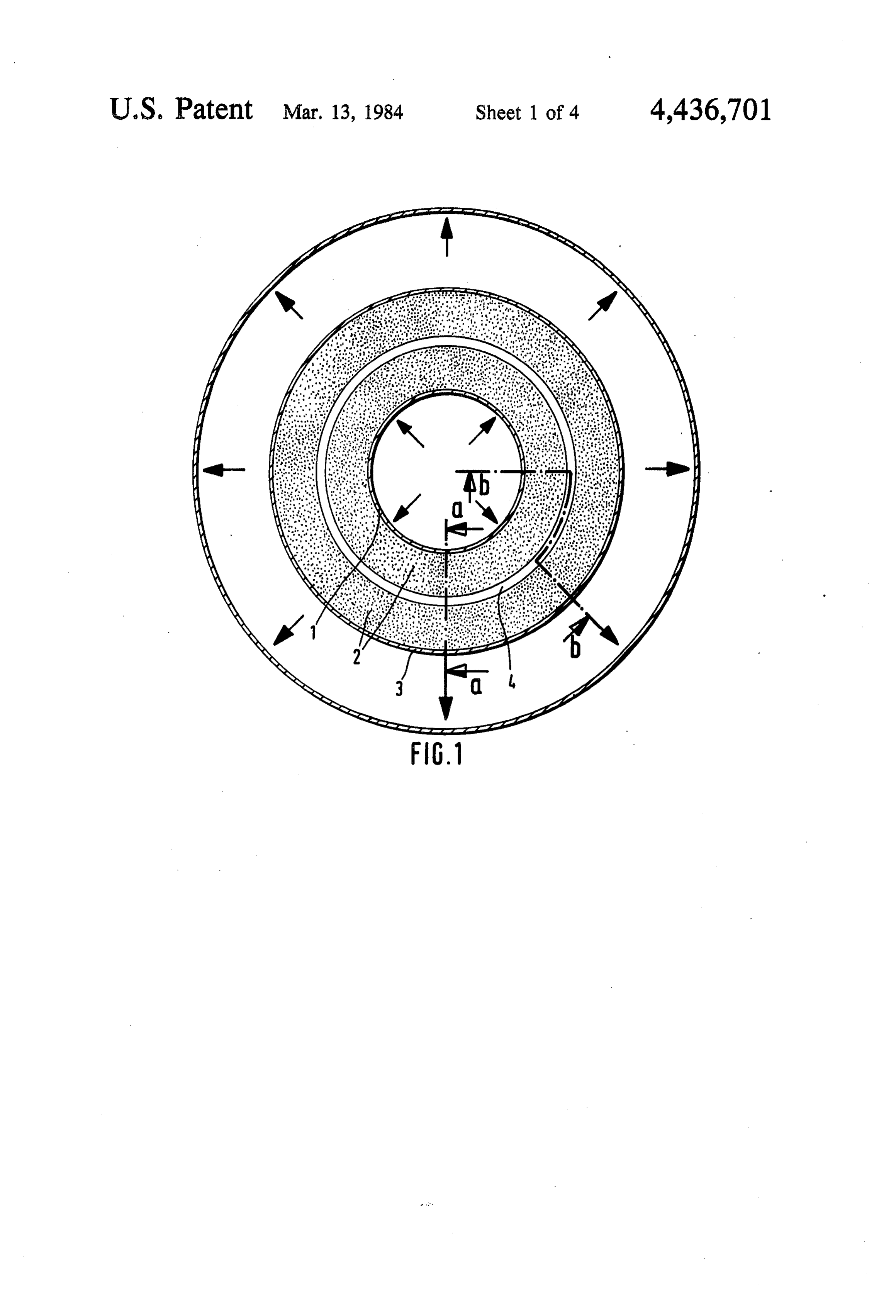
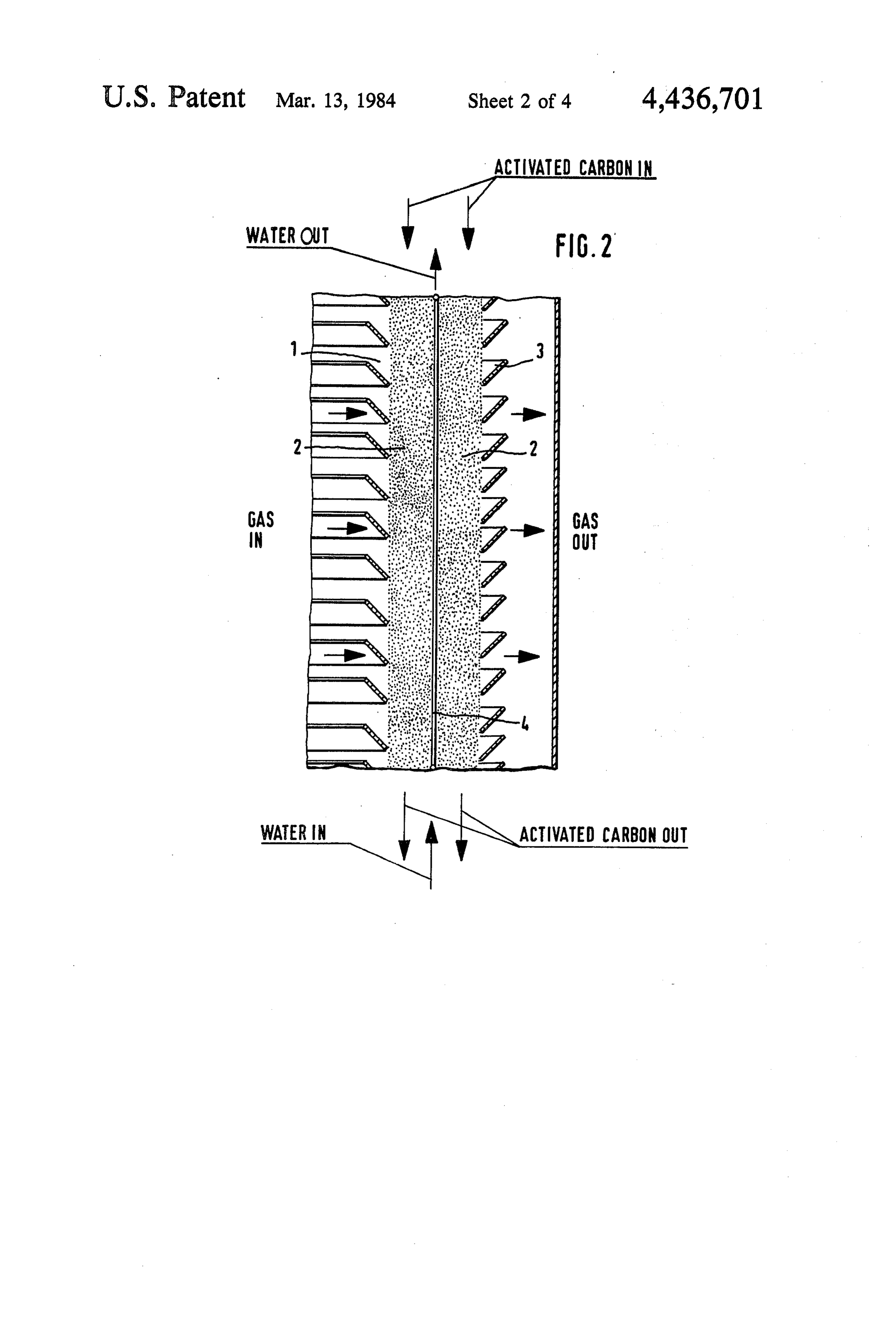
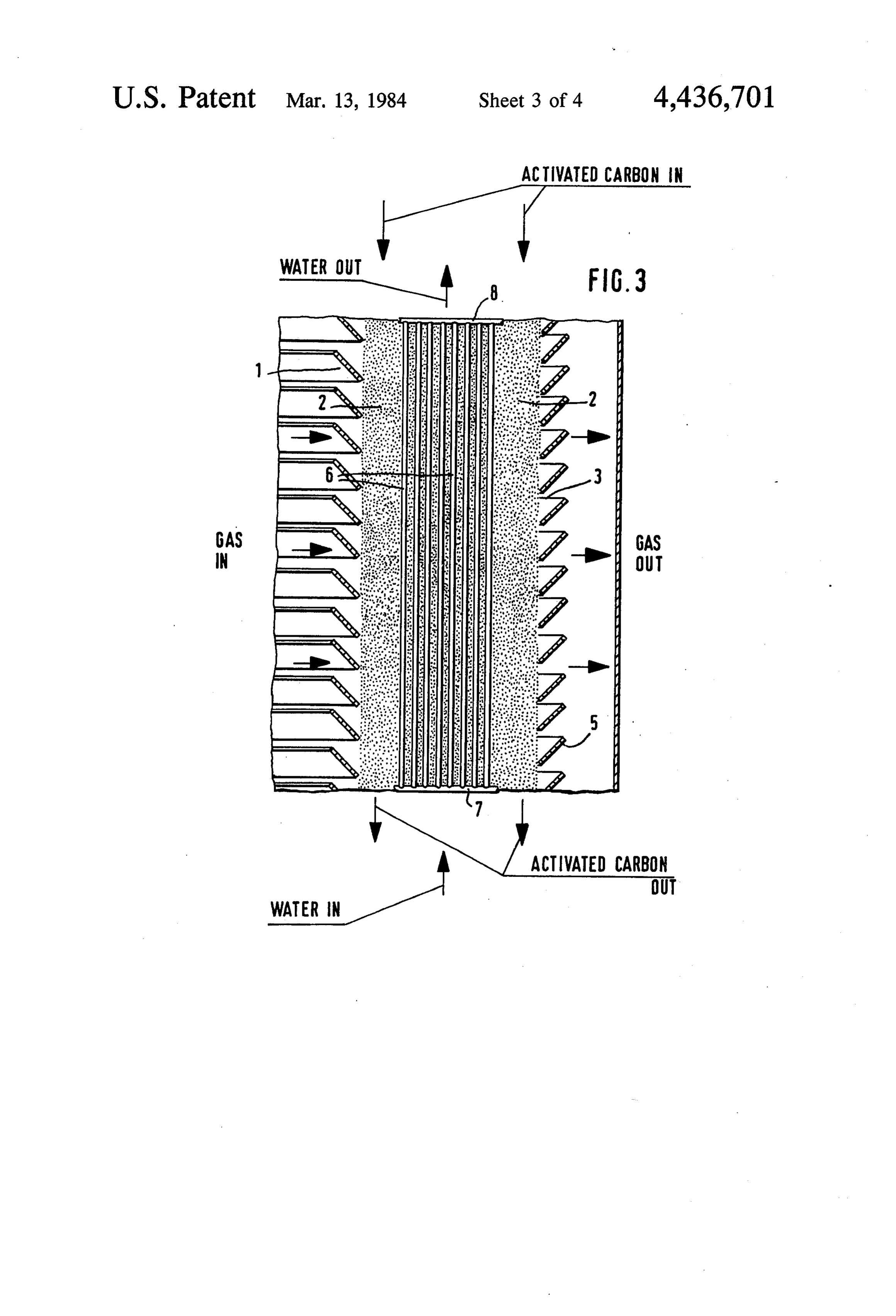
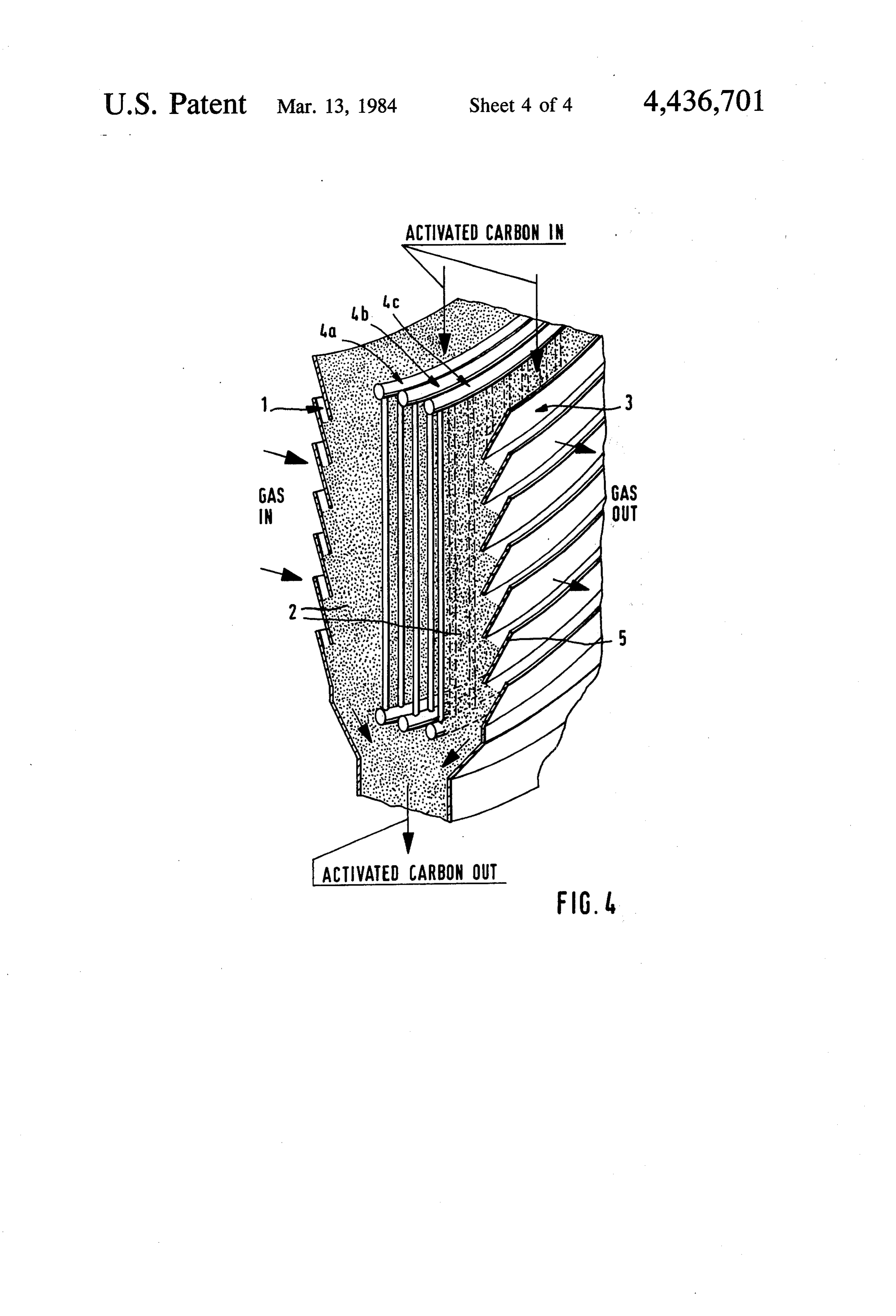
FIG. 3 is a view substantially corresponding to the
FIG. 1 is a view showing across section of an adsorp carbon-containing adsorption medium in form of acti tion reactor in accordance with the present invention; vated coal or molecular filters.
Page 2drawing sheetscan →
Page 3drawing sheetscan →
Page 4drawing sheetscan →
Page 5drawing sheetscan →
Page 6scan →
FIG. 3 is a view substantially corresponding to the
ADSORPTION REACTOR AND METHOD FOR view of FIG.2 but showing alongitudinal section of the REMOVING SO2 FROM WASTE GASES inventive reactor taken along the line b-b in FIG. 1; and
BACKGROUND OF THE INVENTION s FIG. 4 is a perspective view showing the inventive adsorption reactor in accordance with a further em
The present invention relates to an adsorption reactor bodiment and an adsorption method for removing SO2 from waste of the invention, gases. During adsorptive removal of SO2 from waste DESCRIPTION OF THE PREFERRED gases with the aid of the above mentioned adsorption O EMBODIMENTS reactors, the separation degree of SO2 is improved by An adsorption reactor in accordance with the present reducing the temperature of the waste gases to, for invention example, below 120' C. It has been tried to introduce cylindricalis ribbed shown in FIG. 1 and has an approximately wall 1 and a second ribbed wall 3 cold fluid into the waste gas prior to its entrance into which extends substantially parallel to the ribbed wall 1. the adsorption reactor. Such a method has the disadvan 15 Abed of an adsorption medium 2 is located between the tage that it involves increase of the volume of the gas ribbed walls 1 and 3. A waste gas flows in a direction and also wrong utilization of the heat content of the transverse to the bed of adsorption waste gases. A further problem is that the waste gas, through the ribbed wall 1 into the layermedium of 2 first adsorption prior to the entrance into the adsorption medium bed, medium 2 and then leaves the adsorption reactor must have always sufficiently high temperatures for 20 through the ribbed wall 3. In accordance with the in avoiding corrosion by falling below the dew point of ventive feature of the present invention, a heat ex sulfuric acid. Thus, there are two contradicting require changer 4 is arranged between the ribbed walls 1 and 3 ments as to the temperature supply in or prior to adsorp in the adsorption medium bed 2. The heat exchanger 4 tion reactors. It has been shown that during the above extends substantially parallel to the ribbed walls 1 and 3 mentioned introduction of a fluid before the adsorption 25 and is permeable for a gas flow. medium bed no adsorption problem takes place. How As can be seen from FIG. 2, the ribbed walls 1 and 3 ever, the introduction for example of water in the waste have a plurality of ribs or lamellas 5 which are inclined gas prior to the entrance into an adsorption reactor and offset relative to one another. The adsorption me filled with carbonaceous adsorption medium under fa dium is supplied at the upper end of the adsorption bed vorable conditions, for example complete evaporation, 30 2 and withdrawn at the lower end of the latter. A heat temperatures below 110-120' C. cannot be attained exchanger fluid can flow through the heat exchanger in (see R. Noack, K. Knoblauch, VDI-Berichte No. 267 any direction. It is also possible that in a not shown (1976), pages 37-42). adsorption reactor, which as natural can have not only SUMMARY OF THE INVENTION cylindrical walls but can have flat walls, a waste gas 35 flows through the reactor not only in one direction but
Accordingly, it is an object of the present invention also in another direction.
to provide an adsorption reactor and an adsorption As can be seen from FIG. 3 the heat exchanger 4 has method in accordance with which, with elimination of a plurality of heat exchanging pipes 6 which extend, for corrosion, a temperature decrease which is favorable example, along a direction of displacement of the ad for separation of SO2 is obtained and simultaneously the 40 sorption medium in the adsorption medium bed. The heat content of the waste gas can be utilized. heat exchanging pipes 6 are connected by a common In keeping with these objects, and with others which inlet conduit 7 and a common outlet conduit 8. Such a will become apparent hereinafter, one feature of the row or register of pipes does not disturb either the pas present invention resides, briefly stated, in an adsorp sage of the waste gas, or the movement of the grained tion reactor for removing SO2 from waste gases which 45 adsorption medium.
has a bed of grained adsorption material moving in FIG. 4 shows the inventive adsorption reactor in substantially downstream direction so that a waste gas accordance with a further embodiment of the invention. passes through the bed transversely of the latter, and a The adsorption reactor shown in this Figure is a plate heat exchanger is inserted in the bed of grained adsorp shaped. The heat exchanger has a plurality of rows or tion material. When the adsorption reactor is designed 50 registers of pipes. The rows are identified by reference and the adsorption method is performed in accordance numerals 4a, 4b and 4c. Each row includes a plurality of with the present invention, the above mentioned disad pipes arranged one near the other. Each row extends vantages of the prior art are eliminated and the above transverse to the gas flow direction, whereas the rows mentioned objects of the present invention are attained. are offset from one another in the gas flow direction. The novel features which are considered characteris 55 The waste gases from which SO2 is separated are tic for the invention are set forth in particular in the generally fumes or flue gases of power plants. How appended claims. The invention itself, however, both as ever, the invention can also be used for other installa to its construction and its method of operation, together tions in which a gas mixture is produced and SO2 or with additional objects and advantages thereof, will be other corrrosive gases must be separated therefrom. best understood from the following description of spe The bed of grained adsorption medium travels inside cific embodiments when read in connection with the the reactor from above downwardly in a continuous or accompanying drawing. stepped manner. The adsorption medium is basically a
Brief description of the drawing
medium which provides for a maximum adsorption efficiency for SO2 or other corrosive gases, particularly
FIG. 1 is a view showing across section of an adsorp carbon-containing adsorption medium in form of acti tion reactor in accordance with the present invention; vated coal or molecular filters.
FIG. 2 is a longitudinal section of the adsorption The heat exchanger inserted in the adsorption me reactor in FIG. 1, taken along the line a-a; dium bed does not undesirably affect either the flow of 7 the waste gas or the moving of the adsorption medium. formed as a pipe with an opening width of 20 mm and When the heat exchanger is formed as a row of pipes a wall thickness of 2.5 mm with three pipe rows each arranged near one another as shown in FIG. 3, a suffi having 100 rows. These pipe rows are arranged at dis cient space remains between neighboring pipes for pas tances of 0.41, 0.81 and 1.23 m from the throughflow sage of the waste gas. The row of pipes is introduced surface of the adsorber parallel to the latter, as shown in into the adsorption medium bed in a plane transverse to FIG. 4. The adsorption medium moves through the the direction of gas flow, and advantageously the direc adsorption reactor from an upper supply point to a tion of the pipes is identical to the moving direction of lower discharge point in substantially 60 h. the adsorption medium. The heat exchanger including The concentration of SO2 of the waste gas is reduced several such rows arranged parallel to one another at O to 0.03 vol.-% (gas desulfurization degree 97%). The distances from one another, as shown in FIG. 4, further waste gas has an average outlet temperature from the improves the above mentioned characteristics. The adsorption reactor of 90° C. Cooling water flows adsorption reactor itself is designed so that it provides through the pipes parallel with a volume flow of total for a maximum possible throughflow surface for the gas 520 m3/h and is heated from 60' to 100° C. flow with a relatively small throughflow depth. For this 15 When the waste gas flows through the adsorption purpose the walls 1 and 3 through which the gas enters reactor with the same conditions but without passage and exits are formed with the ribs 5 which are inclined through the heat exchanger of a cooling medium, a and offset from one another as shown in FIG. 3. temperature increase of the waste gas because of the When the adsorption reactor is designed and the adsorption heat is approximately by 4°C., and the outlet adsorption method is performed in accordance with the 20 concentration of SO2 is 0.038 vol.-% which corresponds present invention, the waste gas with a relatively high to a desulfurization degree of 62%. temperature can enter the adsorption reactor so that the It will be understood that each of the elements de corrosion danger, because of formation of sulfuric acid, scribed above, or two or more together, may also find a is excluded. At this temperature, which for example lies useful application in other types of constructions differ above 150' C., the sulfuric acid portion of the fumes is 25 ing from the types described above. first separated. This leads to lowering of the sulfuric While the invention has been illustrated and de acid dew point to the value of for example under 45 C. scribed as embodied in an adsorption reactor for remov Thereby the corrosion on the outer walls of the heat ing SO2 and the like, it is not intended to be limited to exchanger is prevented. The heat exchanger further provides for the desired cooling of the fumes to the 30 the tural details shown, since various modifications and struc changes may be made without departing in any temperature with which the separation of SO2 relative way from the spirit of the present invention. to the entrance temperature in the adsorption reactor is Without further analysis, the foregoing will so fully improved. Moreover, the heat removed from the waste reveal the gist of the present invention that others can, gas can be advantageously utilized, for example, sup by applying current plied in a remote heating network. In a surprising man 35 various applications knowledge, without readily adapt it for omitting features that, ner, the consumption on the heat exchange surface with from the standpoint of prior art, fairly constitute essen the heat exchanger inserted in the adsorption medium is tial characteristics of the generic or specific aspects of smaller than when the waste gas directly contacts the this invention.
heat exchanger. Thereby the heat exchanger surfaces can be kept relatively small. Generally speaking, the byWhat is claimed as new and desired to be protected Letters Patent is set forth in the appended claims.
inventive reactor and method provide for simultaneous improvement of the SO2 separation and a particularly like1. from An adsorption reactor for removing SO2 and the waste gases, comprising advantageous utilization of the energy content of the a single bed of a grained adsorption medium moving waste gas and its cooling to the temperatures of, for in a substantially downward direction and ar
It is especially advantageous when the waste gas with ranged so that waste gases pass through said bed in a substantially entrance temperature of the adsorption a gas flow direction transversely of the adsorption reactor first flows through a first region of the adsorp medium movement direction; and tion medium bed and is first cooled in the gas flow 50 a temperature by heat separating permeable member formed exchanger tubes inserted in said single bed direction where in one or more regions of the adsorp of a grained adsorption medium and subdividing tion medium bed the adsorption proceeds further. Fur said single bed into at least a first adsorption layer ther temperature decrease can take place between the located upstream of said heat exchanger pipes in individual regions of the adsorption medium bed. said gas flow direction so that waste gases pass said EXAMPLE 55 first adsorption layer at a higher temperature, and a A conventional activated coal with a specific surface second adsorption layer located transversely adja of 500 m2/g, indicated as Brunauer Emmett and Teller, cent to said first adsorption layer and downstream is used as a carbon-containing adsorption medium. The of said heat exchanger pipes in said gas flow direc moving bed reactor has a cross sectional area transverse tion so that the waste gases pass second adsorption to the flow direction of the waste gas of 135 m2 and has layer at a lower temperature. a bed depth of 1.66 m. It is filled, in correspondence 2. An adsorption reactor as defined in claim i, wherein said bed of a grained adsorption medium is with its height, with 224 m of the adsorption medium. substantially
With the temperature of 150° C., 120,000 m3/h of tubular. tubular, said heat exchanger being also power plant waste gas (counted in standard conditions) containing 0.1 vol.-% SO2, 6.4 vol.-% O2, and 10.1 65 3. An adsorption reactor as defined in claim 1, vol.-% of water vapor is supplied with a space velocity wherein said heat exchanger includes a row of heat exchanging pipes, arranged in said bed of an adsoprtios (relative to the empty adsorber) of 800 hl (counted at medium.
150 C.) through the moving bed. The heat exchanger is
Page 8scan →
4. An adsorption reactor as defined in claim 3, said of said heat exchanger pipes on said gas flow direc heat exchanger includes a second row of heat exchang tion so that the waste gases pass second adsorption ing pipe, said rows of heat exchanging pipes being layer at a lower temperature. spaced from one another in a direction of passage of 6. A method as defined in claim 5, wherein said pass waste gases through the bed of an adsorption medium. 5 ing step includes admitting waste gases with a tempera 5. A method of adsorption for removing SO2 and the ture above substantially 120° C., passing through a first like from waste gases, comprising the steps of region of the bed of a grained adsorption medium with passing waste gases through a single bed of a grained fluid-cooling, and further passing the waste gases adsorption medium moving from above down through at least one further region of said bed of a wardly, in a gas passage direction transversely of 10 grained adsorption medium before it leaves the same the adsorption medium movement direction; and with a temperature of below substantially 120 C. arranging a temperature separating permeable mem 7. A method as defined in claim 6; and further com ber formed by a heat exchanger in the bed of the prising the step of increasing cooling between the re grained adsorption medium and subdividing said gions of the bed of a grained adsorption medium, in a single bed into at least a first adsorption layer lo 15 direction of passage of gases through the bed of an cated upstream of the heat exchanger pipes in said adsorption medium.
gas flow direction so that waste gases pass said first 8. A method as defined in claim 6, wherein said fluid adsorption layer at a higher temperature, and a cooling step includes utilization of a cooling fluid for second adsorption layer located transversely adja remote thermal heating.
cent to said first adsorption layer and downstream 20
Provenance
- Collection
- Patents citing this work
- Pages
- 8
- Method
- pdftotext (the PDF's own text layer) + pdftoppm 300dpi page scans
- Patent office record
- patents.google.com →
- Source
- Google Patents citing-documents table
- Assignee
- Bergwerksverband Gmbh
- Published
- 1984-03-13
- Transcribed from
- patentimages.storage.googleapis.com →