

patent · US4437314A
Atomizer nozzle for continuous fuel injection
20 March 1984
Text
Page 1bibliographic recordscan →
United States Patent (19)
Collin
54 ATOMIZER NOZZLE FOR CONTINUOUS
FUEL NJECTION
(75) Inventor: Karl-Heinz Collin, Wehrheim, Fed.
Rep. of Germany Assignee: Klöckner-Humboldt-Deutz
Aktiengesellschaft, Cologne, Fed.
Rep. of Germany
(30) Foreign Application Priority Data
51 Int. Cl. ................................................ FO2C 7/18 52 U.S. C. ................................... 60/738; 239/427.5;
Field of Search .................. 239/427.5, 427.3, 428,
986,663 3/1911 Weintz. ... 239/428 1430,327 9/1922 Sauer ... 431/243 i,629,253 5/1927 Breese ................................... 431/63 1,849,125 3/1932 Valjean ................................. 431/63 1,864,647 6/1932 Geer .................................... 239/428
2,103,328 12/1937 Hansen .................................. 431/62 2,157,265 5/1939 Pothier et al. ...................... 431/243 2,701,608 2/1955 Johnson ....... ... 43/353 2,796,118 6/1957 Parker et al. ... 431/353 3,150,708 9/1964 Davis et al. ......................... 431/352 3,779,694 12/1973 Zagoroff............................. 431/352
FOREIGN PATENT DOCUMENTS
Primary Examiner-Samuel Scott
Assistant Examiner-Noah Kamen
Attorney, Agent, or Firm-Becker & Becker, Inc.
An atomizer nozzle for continuous fuel injection is pro vided. The nozzle can serve as a main injection nozzle or as an igniter for combustion chambers, and is pro vided with a single-hole fuel nozzle, and an annular gap for possible additional air supply located coaxially therebefore. The chamber or space between the nozzle opening and the annular gap is connected by pressure equalization openings with the combustion chamber behind or after the annular gap. The pressure equaliza tion openings are represented and defined by individual spacers between the fuel nozzle body and the air nozzle ring.
2 Claims, 4 Drawing Figures
Drawings
Page 2drawing sheetscan →
Page 3drawing sheetscan →
Page 4drawing sheetscan →
Page 5scan →
ing capacity for the fuel atomization, with the present
ATOMIZER NOZZLE FOR CONTINUOUS FUEL inventive injection nozzle approximately 0.5 to 3.0 NJECTION (W/g/s) suffices. The atomization of the liquid is so fine that a liquid mist results which is spread or dispersed by
The present invention relates to an atomizer or spray 5 the supplied air. The spray or injection angle therefore nozzle for continuous fuel injection, preferably in com results from the air and not from the direction of the bustion chambers of gas turbines, and has a central fuel feeding.
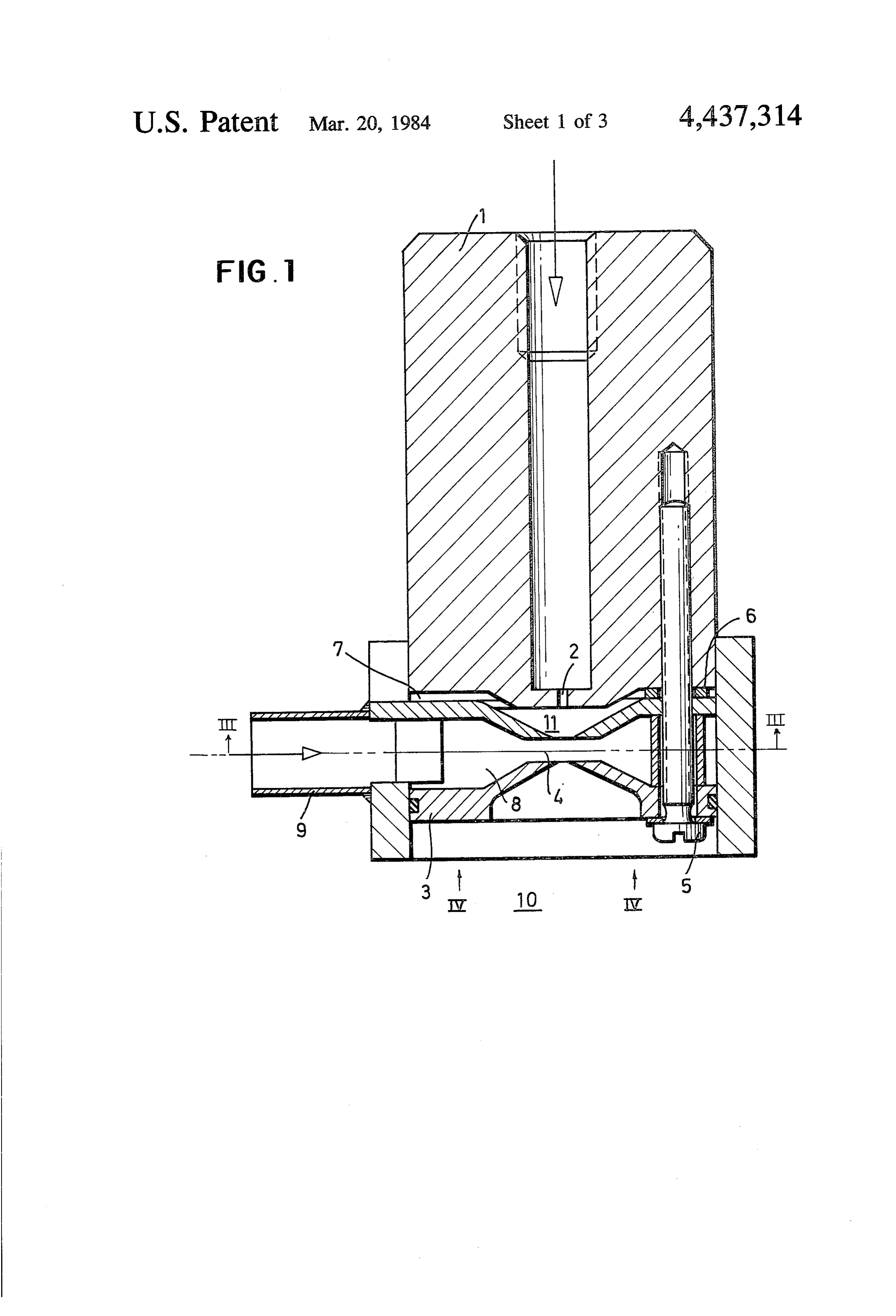
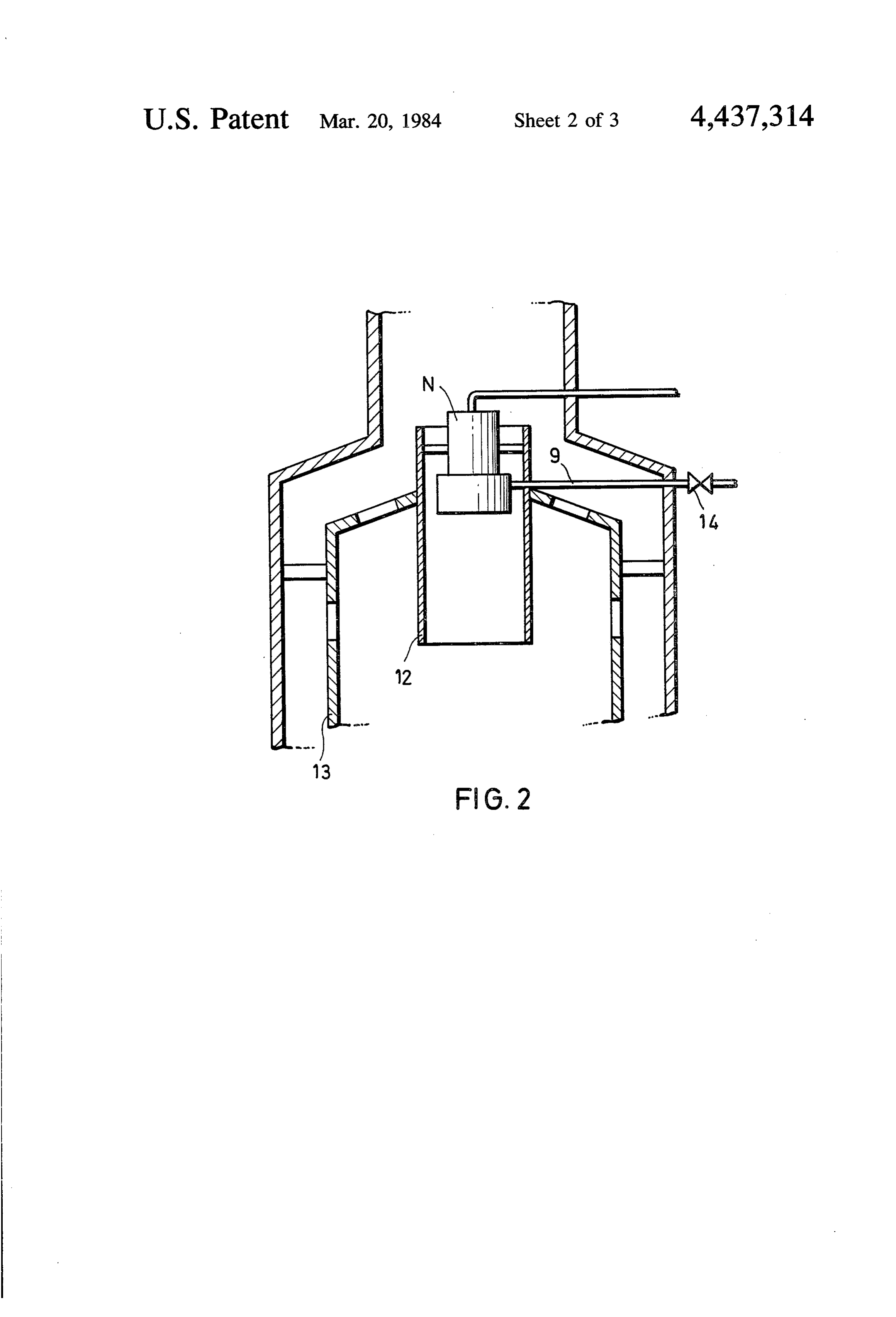
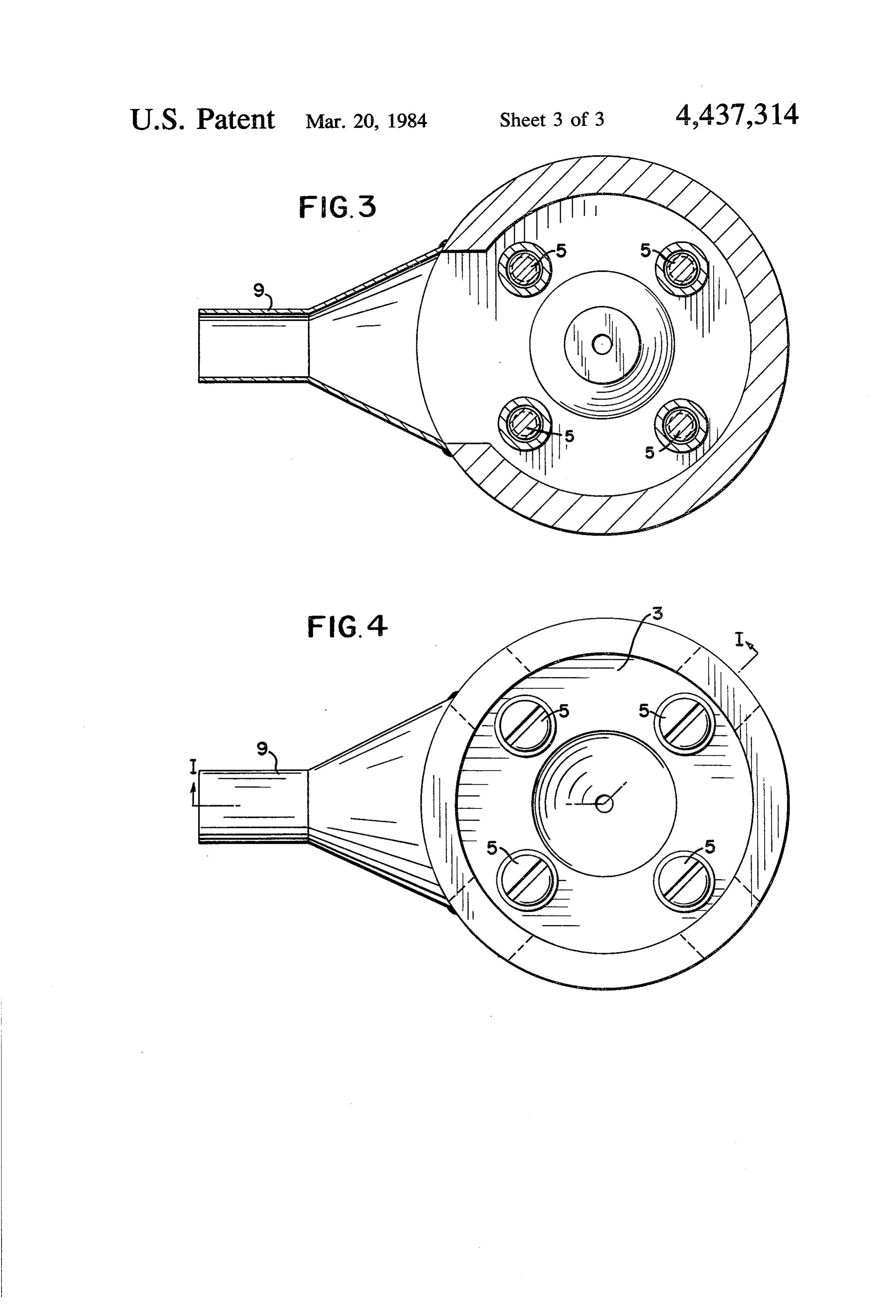
nozzle body for fuel feeding, and an arrangement con With one specific inventive embodiment, the atom centric thereto for annular air supply. izer nozzle comprises an individual nozzle body with a An atomizer nozzle of the indicated type is known O central nozzle bore, and a separate annular body with an according to which the air coming from the compressor annular nozzle. During connection by means of screws is annularly guided in a nozzle concentric to the nozzle or rivets, pressure equalization openings are formed body; and a twist device located in the vicinity of the between the two parts by the gaps between the spacers nozzle opening is supposed to effect an improvement of placed between or rigidly arranged on one of the parts. the atomization (German Offenlegungsschrift No. 1501 15 The air supply is effective according to one special 934). Since the air and the fuel essentially move in the inventive embodiment by an annular nozzle which gen same direction, a swirling of fuel and air occurs at most erates a well-defined stream with a narrowed gap. The in an external zone of the fuel stream or flow. The twist atomizing effect can be further increased hereby. device creates a pressure loss without obtaining the If the injection nozzle is installed in combination with intended effect. 20 vaporizer tubes, as used on gas turbine annular combus It is an object of the present invention to provide a tion chambers, the generation of a fuel mist is only simple atomizer nozzle for continuous fuel injection necessary in the starting phase. In all other drive mecha which operates without movable parts and assures a nism operating conditions, the nozzle operates as a sim high degree of atomization with little extra air. ple injection tube, so that the air supply inventively This object, and other objects and advantages of the 25 turned is off. The fuel vaporization is then taken over present invention, will appear more clearly from the exclusively by the heated vaporizer tubes. following specification in connection with the accom In accordance with specific features of the present panying drawings, in which: invention, the annular gap may have a more restricted FIG. 1 is a section through an atomizer nozzle in or narrower cross section than does an annular chamber accordance with the present invention; 30 in the annular body, whereby an annular nozzle is FIG. 2 shows the inventive atomizer nozzle installed formed.
in a vaporizer tube. The annular body and the nozzle body may be separa FIG. 3 is a cross section view taken along line III bly or detachably connected with each other, whereby -III in FIG. 1; and several spacers form pressure equalization openings FIG. 4 is a view taken in the direction of arrows Ivin 35 therebetween.
FIG. 1. With a vaporizer tube downstream in the combustion The nozzle of the present invention is characterized chamber, the nozzle, for injection of a smooth or even primarily in that the nozzle body has a coaxial, open stream into the vaporizer tube, has a blocking device in nozzle bore; in that the connection with the air supply the air supply conduit which is connected with the comprises an annular body with an inner annular gap, 40 annular chamber in the annular body, whereby the air is which is arranged in a plane at right angles to the axis of shut off after the combustion chamber operating ten the nozzle bore, whereby the air supply from the annu perature is reached.
lar gap occurs in this plane and is directed radially sym Referring now to the drawings in detail, the nozzle metrically inwardly; in that the annular gap is arranged body 1 with the central nozzle bore 2, is connected by after the nozzle bore, in the direction of injection; and in 45 screws 5 with an annular body 3 having an annular gap that an inner chamber is provided between the nozzle 4. Spacers 6 in the form of washers are arranged be bore and the annular gap, which inner chamber is con tween the nozzle body 1 and the annular body 3, as a nected with the surroundings by vents or pressure result of which the vents or pressure equalization open equalization openings. ings 7 are created. The annular body 3 has an inner The atomization of a fuel stream is based essentially 50 annular chamber 8 into which an air supply circuit 9 upon the disturbance of the surface tensions of the liq opens or discharges. The pressure equalization openings uid cylinder which forms after the stream leaves the 7 represent the connection of an inner chamber 11, nozzle bore. If for disturbing the surface tension, there which is located between the nozzle bore 2 and the is utilized an air stream which inventively discharges annular gap 4, and the surroundings 10, such as a burner from an annular gap arranged around the free fuel 55 or combustion chamber, which is located externally of stream, so that the air meets the fuel stream radially the annular body 3.
symmetrically in a perpendicular plane, then small FIG. 2 shows the inventive atomizer nozzle N of quantities of air and a low air pressure, and hence a low FIG. 1 installed in a vaporizer tube 12, which in turn is air conveying capacity, are sufficient for atomizing a arranged in a combustion chamber 13. In order to be predetermined fuel quantity. An important feature of 60 able to shut off the air supply to the atomizer nozzle N this atomization nozzle consists in that the fuel stream once the operating temperature of the combustion discharges into a chamber as a free stream, which cham chamber 13 has been reached, a blocking device or ber has the same pressure as the chamber in which the shut-off valve 14 is arranged in the air supply conduit 9. fuel vapor or mist is conveyed. For this purpose, the The present invention is, of course, in no way re inventive pressure equalization openings are provided, 65 stricted to the specific disclosure of the specification by means of which the air conveying capacity necessary and drawings, but also encompasses any modifications for atomization can be clearly reduced. While the within the scope of the appended claims. known embodiments require 10 to 25 (W/g/s) convey What I claim is:
Page 6scan →
1. An atomizer nozzle arrangement specifically used opening coincident with the axis thereof which for continuously injecting fuel into a combustion cham opening is aligned with but spaced from the outlet ber of a gas turbine engine, wherein the nozzle atomizes of the bore and through which the spray of fuel and the fuel without utilizing moving parts and with mini air from said hollow annular body pass; the hollow mum utilization of intake air, the nozzle arrangement annular body having a front wall and a rear wall comprising in combination: each of which have concave portions adjacent the an air intake communicating with the combustion axial opening;
chamber; an opening communicating the space between the a vaporizor tube within the combustion chamber; back wall of the chamber and the annular body a nozzle body positioned within the vaporizor tube in 10 with the space between the vaporizor tube and spaced relating therewith to define a space therebe nozzle body for pressure equalization; tween through which space a portion of the intake an air supply conduit connected radially with the air passes; the nozzle body having a bore there through for delivering fuel therethrough, the bore interior of the hollow annular body for supplying having a fuel outlet of a smaller diameter than the 15 pressurized air thereto, and bore, from which outlet a spray of fuel is ejected; means for interrupting airflow through the air supply a circular chamber in the nozzle body and positioned conduit so that the air supply can be stopped when downstream from the outlet, through which cham the temperature of the combustion chamber ber the spray of fuel passes, the chamber having a reaches operating temperature.
back wall through which the outlet of the bore 20 2. The atomizer nozzle arrangement of claim 1 passes; wherein the annular body is secured to the back wall of an annular body having a hollow interior and dis the nozzle body by a plurality of screws and wherein posed in the circular chamber in spaced relation to the space between the annular body and back wall of the back wall of the chamber to define a space the chamber is created by space washers disposed be between the back wall of the chamber and annular 25 tween the annular body and back wall.
body; the hollow annular body having an axial k k k k
Provenance
- Collection
- Patents citing this work
- Pages
- 6
- Method
- pdftotext (the PDF's own text layer) + pdftoppm 300dpi page scans
- Patent office record
- patents.google.com →
- Source
- Google Patents citing-documents table
- Assignee
- Klockner-Humboldt-Deutz Aktiengesellschaft
- Published
- 1984-03-20
- Transcribed from
- patentimages.storage.googleapis.com →