

patent · US4437963A
Apparatus for electrolyzing water
20 March 1984
Text
Page 1scan →
United States Patent (19)
Yeoman
54 apparatus for electrolyzing
Water
76 Inventor: David R. Yeoman, 869 Concourse
Village West, Bronx, N.Y. 10451
52 U.S. C. .................................... 204/229; 204/237;
1,310,727 7/1919 Zorzi............................... 204/278 X 3,647,672 3/1972 Mehandjiev ..... ... 204/278 X 3,870,893 3/1975 Mattera ................................. 290/53 3,969,214 7/1976 Harris ...... ... 204/129 X 4,239,976 12/1980 Collard ............................. 290/53 X
Foreign patent documents
2301709 9/1976 France ................................ 204/129 Primary. Examiner-Donald R. Valentine
Attorney, Agent, or Firm-Steinberg & Raskin
Apparatus for the electrolysis of water comprises an elongated tube and an electrolysis assembly provided at one end of the tube defining an interior chamber which constitutes an extension thereof. The electrolysis assem bly includes at least one fixed stator and at least one rotatably mounted rotor and drive means for rotating the rotor in the form of propeller blades mounted on a shaft which is connected to a transmission to the rotor. A pair of fixed electrodes extend across the interior chamber of the electrolysis assembly. A matrix of Wie gand modules are affixed to the rotor and a correspond ing matrix of magnet pairs are fixed to the stator. Ap propriate circuitry is provided which couples the posi tive and negative leads of the Wiegand modules to re spective ones of the electrodes. When the tube is im mersed in a body of water so that its upper end extends out from the water and so that the electrolysis assembly is completely immersed, water tends to rush into the interior chamber under equilibrium forces whereby water tends to seek its own level to rotate the drive means thereby rotating the rotor relative to the stator whereupon the Wiegand modules generate a voltage which is impressed across the electrodes to electrolyze water which comes into contact therewith.
10 Claims, 6 Drawing Figures
Drawings
Page 2drawing sheetscan →
Page 3drawing sheetscan →
Page 4scan →
various magnetic field values are attained. This sudden
APPARATUS FOR ELECTROLYZING WATER snapping action is the well-known "Barkhausen jump”
Background of the invention
and such jumps can be detected by a coil wrapped around the material and in which a small voltage is
It has long been recognized that if the hydrogen on generated as described above.
earth were readily accessible it could become a major The Wiegand wire essentially constitutes a wire and virtually unlimited source of energy. For example, formed of vicalloy (vanadium cobalt alloy) which is when cooled and liquified, it could serve as fuel for work-hardened by suitably twisting and tempering the modified internal combustion engines and when passed 10 same so that it has a permanent deformation that heli through fuel cells, it could generate electricity. cally winds around its circumference. Such configura However, most of the hydrogen found on the earth is tion forces the domains in the Wiegand wire to maintain bound with oxygen in the form of water. For this rea their polarity when exposed to an increasing magnetic son, there have been numerous attempts to develop field until a certain threshhold is reached at which time techniques of splitting water into its two components, 15 the domain abruptly undergoes a single “leap', i.e., the hydrogen and oxygen. Most recently, attempts have polarities of all of the domains are reversed simulta been made to achieve such splitting by photosynthesis. neously. The effect of the magnetic leap is enhanced by In one such arrangement, spinach chloroplasts are the wires twisted-in tension which renders it bistable. placed in a solution containing various substances in cluding enzymes which speed up the reaction. In effect The magnetic leap produces pulses that can be detected the energy of the sun is captured by the chloroplasts sourcepick-up coil wrapped around the wire. No power needed to pick up the pulse.
which use the energy to disassociate a molecule of water into its component parts, hydrogen and oxygen. coil wound around awhich
Wiegand modules comprise a copper sensing short piece of Wiegand wire as
This technique, although promising, has not as yet well as literature describing the operating parameters of proven feasible for commercial applications.
It has been known for many years that water can be 25 the same, are available from Sensor Engineering Co. of split by electrolysis whereby an electric current passed Hamden, Conn.
through water breaks the bond between the hydrogen Briefly, the present invention incorporates a matrix of and oxygen atoms in the water molecules thereby re Wiegand modules in a construction whereby equilib leasing hydrogen as well as oxygen. However, it has not rium forces of a body of water are utilized to create an been possible to adapt electrolysis processes to commer 30 appropriately varying magnetic field to which the Wie cial applications due to the fact that the amount of elec gand modules are exposed whereby a voltage is gener tricity required to produce practical amounts of hydro ated in the respective pick-up coils of the modules. The gen has to the present been prohibitively expensive. voltages are summed and impressed across a pair of SUMMARY OF THE INVENTION grids immersed in the body of water so that the grids act 35 as an anode and cathode, respectively, to electrolyze
Accordingly, one object of the present invention is to the water.
provide new and improved methods and apparatus for In the illustrated embodiment of the invention, the the electrolysis of water. apparatus includes an elongated tube having a substan Another object of the present invention is to provide tially cylindrical configuration over substantially its new and improved methods and apparatus for the elec entire length and which is adapted to be immersed in a trolysis of water wherein substantially no external body of water to obtain a substantially vertical configu source of electricity is required. ration. An electrolysis assembly is provided at the lower In accordance with the present invention, these and end of the tube which includes at least one stator form other objects are attained by utilizing a recently discov ered principle in the field of electro-magnetics. In this 45 ing an enlarged portion of the tube and a rotor rotatably mounted on the tube. The stator defines an interior connection, reference is made to U.S. Pat. No. 3,820,090 chamber which communicates with the interior of the issued June 25, 1974 to John R. Wiegand which dis closes a technique wherein a wire (hereinafter, a “Wie cylindrical tube and a pair of grids extend in proximate gand wire') is specially treated so as to possess a unique ber. A drivetomechanism relationship each other transversely across the cham in the form of one or more magnetic property whereby when it is moved past a 50 rotary propellerblades is mounted magnet, the polarity of the Wiegand wire will rapidly suitably coupled to the rotor in a inmannerthe chamber and is such that as shift and generate strong electrical pulses without any external power being supplied. Thus, by this technique, water passes the blades to rotate the same, the rotor is caused to continuously rotate in close proximity to the the magnetic fields in a suitably prepared wire can be StatOr.
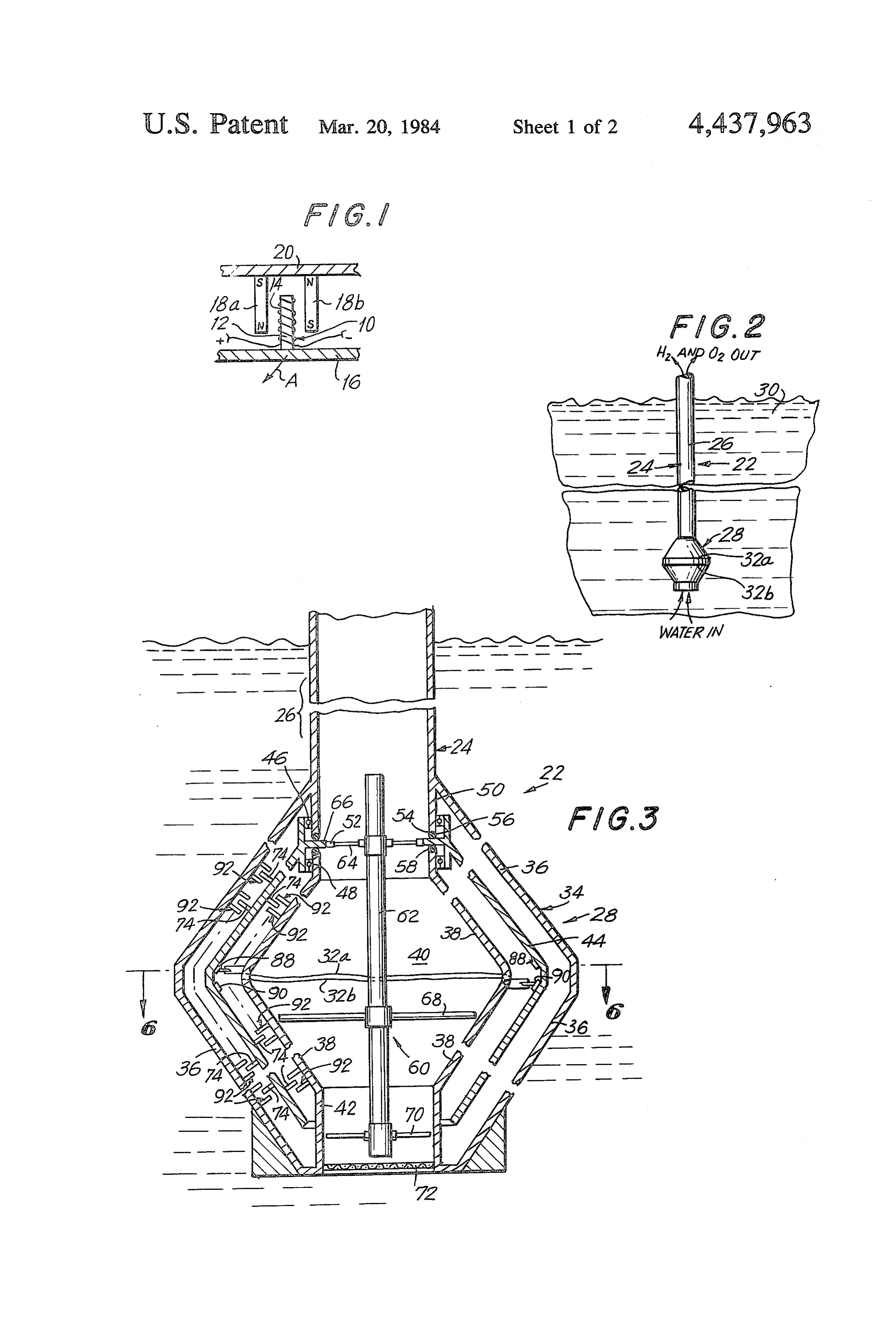
made to reverse suddenly and this phenomenon can be 55 used to generate sharp, uniform electrical pulses. Such A matrix of Wiegand modules are fixed to the rotor pulses can be produced using only a short length of and a corresponding matrix of magnets are fixed to the wire, a permanent magnet, and a pick-up coil. stator. The rotor, stator, Wiegand modules and magnets Thus, in an unmagnetized ferrous magnetic material, are arranged such that with each rotation of the rotor, the magnetized regions or domains are randomly ori 60 the Wiegand modules will approach and pass in proxim ented and thereby cancel each others magnetic effect. If ity to a plurality of magnets whereby during rotation, the material is placed in an external magnetic field, the each Wiegand wire will see a continuous series of ap domains gradually shift polarity to line up with the propriate excursions in magnetic field strength resulting applied field until the material becomes magnetically in the generation of continuous series of voltage pulses. Saturated, i.e., all its domains are neatly lined up in the 65 Each of the pair of leads extending from each of the direction of the field. However, if the magnetic field is pick-up coils of each Wiegand module is connected to a increased in a gradual manner to its full strength, the corresponding one of the pair of grids, respectively, domains will "snap' into alignment at different times as through suitably arranged circuitry whereby the gener 5 ated voltages are summed and impressed across the pair about the same length as the Wiegand wire or Wiegand of grids. module and should be substantially parallel to it. Fur In operation, the apparatus is immersed into a body of ther discussion of the principle and theory of the Wie ionizable water until the tube is substantially entirely gand effect is beyond the scope of the instant applica immersed therein with only its upper end extending into tion, it being understood that those skilled in the art will the atmosphere and with the electrolysis assembly being readily understand the manner in which the dimensions, situated at the lower immersed end. It will be under gauss levels of the magnets and other design criteria can stood that the interior of the tube as well as the interior be obtained for its use herein, chamber of the electrolysis assembly is initially devoid Referring now to FIG. 2, the apparatus 22 of the of water. After immersion, water enters the lowermost O present invention comprises a tube 24 preferably having end of the electrolysis assembly and begins to flow a cylindrical configuration over the major portion 26 of upwardly under equilibrium forces and passes the pro its length. For example, the cylindrical portion 26 of pellers which are thereby caused to rotate which in turn tube 24 may have a length of about 130 feet. An assem rotates the rotor through an appropriate transmission. bly 28 for electrolyzing water forms a terminal exten Rotation of the rotor results in appropriate voltages 15 sion of tube 24. As described in detail below, electrolyz being generated by the Wiegand modules which are ing assembly 28 incorporates a matrix of Wiegand mod impressed across the pair of electrolysis grids which act ules and magnets provided on rotor and stator structure. as electrodes to electrolyze the water as the same rises In the operation of the apparatus which will also be into contact therewith, the hydrogen and oxygen gases described in detail below, the tube 24, whose interior is being formed by the electrolysis being transmitted up 20 devoid of water, is immersed in a body of water 30 until wardly through the tube to exit from the upper end it obtains a substantially vertical orientation and so that thereof. only its uppermost extends out of the water. As soon as DESCRIPTION OF THE DRAWINGs this positioning is completed, water will begin to rush into the bottom of the tube 24 into an interior chamber
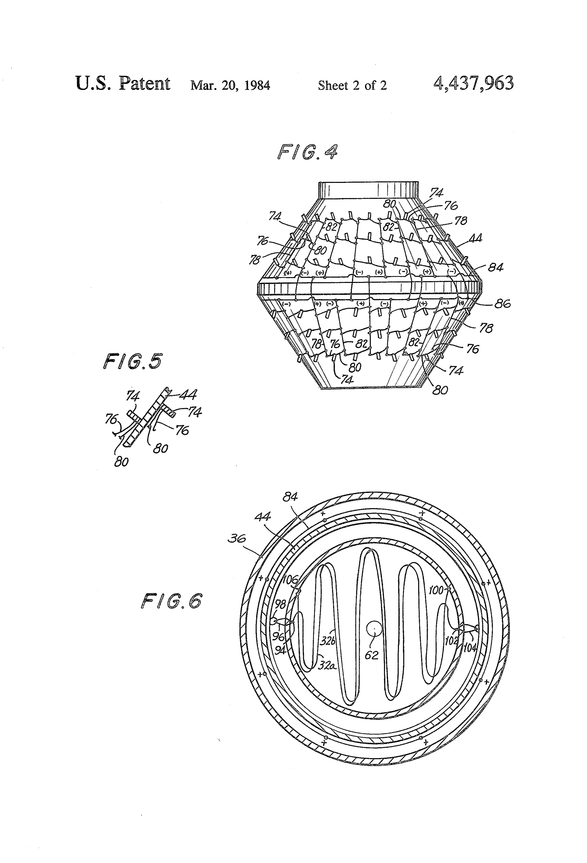
A more complete appreciation of the present inven 25 defined within the electrolyzing assembly 28 under the tion and many of the attendant advantages thereof will equilibrium forces whereby water tends to seek its own be readily appreciated as the same becomes better un level. The rush of incoming water rotates propeller derstood by reference to the following detailed descrip blades which are mounted within the interior chamber tion when considered in connection with the accompa which rotates the rotor through a suitable transmission. nying drawings in which: 30 This results in the Wiegand module "seeing' an appro FIG. 1 is a schematic view of a Wiegand module and priately varying magnetic field whereby a voltage is associated magnet illustrating the operation thereof; generated which is impressed across a pair of grids 32a FIG. 2 is a schematic view of the apparatus of the and 32b which extend transversely across the interior present invention; chamber of assembly. 28. The water reaching grids 32 is FIG. 3 is a schematic view illustrating in detail the 35 electrolyzed with resulting hydrogen and oxygen gas construction of the electrolysis assembly of the present being collected as it exits from the upper end of tube 24. invention; Since substantially entirely all of the water is electro FIG. 4 is a schematic view of the rotor of the electrol lyzed, the process will continue for long periods of time ysis assembly of the present invention illustrating the as the water will contintinuously rush into the lower Wiegand modules circuitry associated therewith; end of tube 24. w FIG. 5 is a partial section view of the rotor of the Turning now to FIGS. 3-6, the illustrated embodi electrolysis assembly of the present invention; and ment of the apparatus 22 of the invention includes tube FIG. 6 is a section view taken along lines VI-VI of 24 whose major portion 26 has a substantially cylindri FIG. 3 and illustrating the electrolysis grids. cal configuration. Tube 24 terminates at its lower end in 45 the electrolyzing assembly 28. More particularly, elec
DESCRIPTION OF THE PREFERRED trolyzing assembly 28 comprises a substantially closed EMBODIMENTS double-wall shell-like structure 34. This shell-like struc Referring now to the drawings wherein like refer ture 34 is defined by an outer wall or stator 36 which ence characters designate identical or corresponding integrally extends from and is thereby supported by parts throughout the several views, FIG. 1 schemati 50 tube portion 26 and an inner wall or stator 38 which cally illustrates a Wiegand module 10 constituted by a follows the shape of the outer stator 36. The shell-like Wiegand wire 12 having a pickup coil 14 wound around structure 34 has an outer configuration which is prefera the same. One end of Wiegand module 10 is embedded bly that of a pair of cones connected at their bases and in a plate 16. A pair of permanent magnets 18a and 18b which defines an interior chamber 40 there within. A are embedded at their reversed polarity ends in a sepa 55 reduced diameter opening 42 is provided at the lower rate plate 20. It will be understood by a person skilled in most end of the shell-like structure 34 through which the art that when plate 16 is moved relative to plate 20 water can enter into chamber 40.
as designated by arrow A so that the Wiegand module A rotor 44 formed by a single wall having a similar 10 passes between magnets 18a and 18b, voltage is gen double cone configuration is situated in the space de erated in the pickup coil 14. The particular design char 60 fined between the outer and inner stators 36 and 38 and acteristics of the Wiegand module and associated mag is rotatably mounted to a cylindrical extension 50 of the nets are chosen in the instant application so as to pro tubular portion 26 coaxially therewith by bearings 46 vide a suitable voltage that will be readily ascertainable and 48 within that space. An annular flange 52 of rotor by a person skilled in the art, such as through experi 44 extends inwardly into the uppermost region of cham mentation. It is sufficient to note herein that in all cases, 65 ber 40 through an annular slot 54 defined between the the Wiegand module 10 must see an excursion in field lower edge of cylindrical extension 50 and the upper strength from one value to another, and from one orien edge of inner stator 38. A pair of seals 56 and 58 are tation to another, in that the magnetic field should be provided for fluidly sealing the space between the outer
Page 6scan →
S 6 and inner stator 36 and 38 from the chamber 40 and yet a sharp electrical pulse and that a plurality of such which permit rotation of rotor 44. pulses will be generated by a particular module during A drive mechanism, generally designated 60, is pro each revolution of the rotor 44. Thus, during rotation of vided within chamber 40 and includes a shaft 62 having rotor 44, a continuous series of positive and negative three propellerblades fixed thereto. An upper propeller electrical pulses will be transmitted through the main blade 64 is fixed to the upper region of shaft 62 and has positive and negative conductors 78 and 82 and positive an outer circumferentially extending rim 66 which is and negative interconnecting conductors 84 and 86 to coupled to the inner edge of flange 52 thereby rotatably the respective positive and negative conducting rims 88 mounting the shaft 62 as shown. It is seen that rotation and 90. When the rotor 44 is rotating at its appropriate of shaft 62 will result in the rotation of rotor 44 through O speed, an appropriate potential difference or voltage the upper propeller 64, rim 66, and flange 52. Of course, generated between the positive and negative conduct other transmissions may be utilized such, for example, ingrims 88 and 90.
as a so-called nutating transmission for transmitting the Referring now to FIGS. 3 and 6, a pair of grids 32a rotation of shaft 62 to rotor 44. and 32b extend transversely across chamber 40 at the An intermediate, larger diameter propeller 68 is fixed 15 major diameter portion thereof. In the illustrated em to shaft 62 somewhat below the large diameter mid-sec bodiment, grids 32a and 32b comprise conductors tion of chamber 40. A third, lower propeller 70 is fixed which follow a serpentine path and which are vertically to the lower region of shaft 62 and is situated within the spaced one over the other in close proximity to each opening 42 defined by the shell-like structure 34. A other. One end 94 of grid 32a is connected to a conduc screen-like filter 72 extends across opening 42 for rea 20 tive roller assembly 96 which includes a roller 98 sons discussed below. adapted to roll over the positive conducting rim 88, the The number of blades in each of the propellers 64, 68 other end 100 of grid 32a being insulatingly connected and 70 as well as the particular configuration thereof is to the inner stator 38. Similarly, one end 102 of grid 32b determined according to their function. Thus, as water is connected to a conductive roller assembly 104 which enters chamber 40 through opening 42 under the equi 25 continuously engages the negative conducting rim 90, librium forces acting thereon, the lower propeller 70 is the other end 106 of grid 32b being insulatingly con cause to rotate thereby initiating the rotation of shaft 62 nected to the stator 38.
and, therefore, of rotor 44. As the water continues to fill It will be seen from the foregoing that as the rotor 44 the chamber 40, it passes through the larger diameter rotates, a potential difference will be applied over con propeller 68 which is designed so as to rotate the shaft 30 ducting rims 88 and 90 which will be impressed over the 62 and rotor 44 at the final desired speed. The water respective grids 32a and 32b through the conductive then rises to the level of grids 32a and 32b over which roller assemblies 96 and 104. Accordingly, during rota a voltage has been impressed as discussed below tion of rotor 44, the grids 32a and 32b will act as an whereby the water is electrolyzed. The hydrogen and anode and cathode, respectively, oxygen gas formed passes upwardly past upper propel 35 In operation, apparatus 22 is immersed into a body of ler 64 which is appropriately designed to adjust the rate ionizable water until the tube 24 extends substantially at which the gas flows outwardly from the chamber 40, vertically with the upper end extending into the atmo Referring to FIGS. 3-5, a plurality of Wiegand mod sphere. Water will begin to rush into the chamber 40 ules 74 are fixed in a regular pattern on both the in under equilibrium forces through filter 72 which pre wardly and outwardly facing surfaces of the rotor 44. vents the entry into chamber 40 of unwanted solid mate As seen in FIG. 4 which illustrates the matrix of Wie rials such as plankton, fish, etc. The opening 42 is appro gand modules provided on the outer surface of rotor 44, priately sized to adjust the amount of water entering the Wiegand modules are fixed to the rotor in circular into chamber 40. As the water rises within chamber 40, arrays extending horizontally around the rotor. It is it passes the lower and intermediate propellers 70 and 68 understood that a similar matrix of Wiegand modules 45 thereby initiating rotation of shaft 62 and, consequently, are provided on the inner surface of rotor 44 as best seen rotor 44 through the transmission connection 66 of in FIG. 3. The positive lead 76 of each Wiegand module upper propeller 64. A fly wheel may be provided to 74 is connected to vertically extending main positive conserve the rotational energy acquired by the rotor. conductors 78 while the negative leads 80 of the Wie The Wiegand modules are of course rotating through gand modules 74 are connected to respective main neg 50 the magnetic fields of the magnet pairs 92 generating a ative conductors 82. The main positive and negative substantially continuous series of positive and negative conductors 78 and 82 terminate at respective intercon pulses which are applied to the grids 32a and 32b in the necting conductors 84 and 86, respectively which are in manner described above. By the time water reaches the turn connected to respective conducting rims 88 and 90 level of grids 32a and 32b, an appropriate potential (FIG. 3) which extend around the inner surface of rotor 55 difference is impressed across the grids to electrolyze 44 at the major diameter portion thereof. the water reaching the same. In this manner, the water A plurality of pairs of magnets 92 are fixed to the is broken down into hydrogen and oxygen gas which outer and inner stators 36 and 38 to form respective passes through the cylindrical portion 26 of tube 24 matrixes. The matrixes of magnet pairs 92 are provided exiting from the same at its upper end. in a pattern such that each magnet pair 92 corresponds It is seen from the foregoing that electrolysis of water to a particular Wiegand module 74 in a manner such is obtained without the necessity of an external power that as the rotor 44 rotates, the Wiegand modules 74 source using the equilibrium forces acting on the water will pass between respective magnet pairs 92 simulta through the apparatus. A suitable valve may be pro neously. It is therefore seen that during one revolution vided in opening 42 in order to control the entry of of the rotor 44, a particular Wiegand module 74 will see 65 water into chamber 40. Further, the present invention is an excursion in magnetic field strength from one value not limited to the particular embodiment illustrated in to another and from one orientation to another as it the drawing. For example, the electrolyzing assembly passes through a particular magnet pair 92 given rise to 28 may be provided with a plurality of rotors and sta 7 tors to provide increased electrical energy through the rotor whereby upon fluid flowing past said propeller, provision of additional Wiegand modules and magnet said shaft is caused to rotate thereby rotating said rotor. pairs. The permanent magnet comprising magnet pairs 3. The combination of claim 1 wherein said magnetic 92 may be replaced by suitable electro magnets. Fur field generating means comprise a plurality of magnet ther, other arrangements for providing the varying pairs affixed to the other of said rotor and stator. magnetic field seen by the Wiegand modules may be 4. The combination of claim 3 wherein said matrix of utilized such, for example, as a rotating shunt or the like. modules are affixed to said rotor and said magnet pairs Obviously, numerous modifications and variations of are affixed to said stator. the present invention are possible in the light of the 5. The combination of claim 4 wherein said circuit above teachings. It is therefore to be understood that 10 means include conductive means for carrying the volt within the scope of the claims appended hereto, the age generated by said modules from said rotor to said invention may be practiced otherwise than as specifi fixed electrodes.
cally disclosed herein. 6. The combination of claim 5 wherein said conduc What is claimed is: tive means comprise positive and negative conducting 1. Apparatus for the electrolysis of water, compris 5 rims connected to said positive and negative leads of ing: said modules respectively and extending around the an elongated tube; inner surface of said rotor, a first conductive roller an electrolysis assembly provided at one end of said assembly electrically coupled to one of said electrodes tube defining an interior chamber constituting an 20 and including a roller engaging said positive conducting extension of said tube, said electrolysis assembly rim and a second conductive roller assembly electri including, cally coupled to the other one of said electrodes and at least one fixed stator and at least one rotatably including a roller engaging said negative conducting mounted rotor, 7. The combination of claim 1 wherein said at least drive means for rotating the rotor adapted to be 25 one stator comprises a shell-like structure defining an driven by a flowing fluid, inner and an outer stator, said rotor being situated be a pair of fixed electrodes extending across said inte tween said inner and outer stators and having a pair of rior chamber, inner and outer surfaces facing said inner and outer a matrix of modules, each module comprising bistable stators, respectively.
magnetic means having a reversing polarity when exposed to an increasing magnetic field and having 30 are8.affixed
The combination of claim 7 wherein said modules respective positive and negative leads, affixed to faces of saidto rotor both of said pair of inner and outer sur and said magnetic field generating one of said rotor and stator and magnetic field means are provided on both said inner and outer stators. generating means provided on the other of said 9. The combination of claim 8 wherein said magnetic rotor and stator, and 35 field generating means comprise a plurality of magnet circuit means coupling said positive and negative pairs affixed to both said inner and outer stators. leads of said modules to respective ones of said 10. An electrolysis assembly for electrolyzing water electrodes; comprising at least one fixed stator defining an interior whereby upon a fluid being caused to flow through chamber and at least one rotatably mounted rotor; drive said interior chamber, said drive means effect rota means for rotating the rotor; a pair of fixed electrodes tion, of said rotor with respect to said stator where extending across said interior chamber; a matrix of mod upon said modules are exposed to continuous ex ules, each module comprising bistable magnetic means cursions in magnetic field strength to generate a having a reversing polarity when exposed to an increas voltage which is impressed across said electrodes ing magnetic field and having respective positive and to electrolyze water coming into contact with the 45 negative leads, affixed to one of said rotor and stator SaC. and magnetic field generating means provided on the 2. The combination of claim 1 wherein said drive other of said rotor and stator; and circuit means cou means comprise at least one propeller mounted on a pling said positive and negative leads of said modules to rotatable shaft located within said interior chamber, and respective ones of said electrodes. transmission means interconnecting said shaft and said 50 k
Provenance
- Collection
- Patents citing this work
- Pages
- 7
- Method
- pdftotext (the PDF's own text layer) + pdftoppm 300dpi page scans
- Patent office record
- patents.google.com →
- Source
- Google Patents citing-documents table
- Assignee
- Yeoman David R
- Published
- 1984-03-20
- Transcribed from
- patentimages.storage.googleapis.com →