

patent · US4440137A
Supplemental fuel supply device for I.C. engine
3 April 1984
Text
Page 1bibliographic recordscan →
United States Patent (19)
Lagano et al.
54 SUPPLEMENTAL FUEL SUPPLY DEVICE
FOR I.C. ENGINE
(75) Inventors: Thomas Lagano, Juno Beach; William H. Batchelor, Jenson Beach, both of
73 Assignee: Propane Carburetion Systems, Inc.,
Stuart, Fla.
(51) Int. Cl. ............................................. FO2M 21/02 52 U.S. C. .............................. 123/525; 123/27 GE;
(58) Field of Search ............... 123/525, 529, 527, 528,
2,279,530 4/1942 Smith .................................. 123/527 2,311,315 2/1943 Smith .................................... 48/18O 2,612,145 9/1952 Steven et al. . 23/27 GE 2,781,030 2/1957 Miller ........ ... 48/184 2,927,848 3/1960 Baverstock ... 48/84 2,928,382 3/1960 Hug ............... 23/27 GE 2,983,592 5/1961 Jones ................................... 123/527 3,443,551 5/1969 Laubach ... 123/27 GE 3,698,365 10/1972 Hallberg .............................. 123/527
3,895,618 7/1975 Cerf ..................................... 123/527 3,905,773 9/1975 Brooks et al. ....................... 123/527 3,948,224 4/1976 Knapp et al... ... 23/3 4,015,571 4/1977 Stumpp ............................... 123/527 4,046,120 9/1977 Laprade et al. ..................... 123/527 4,064,843 12/1977 Holzbaur ............................. 123/527 4,308,843 1/1982 Garretson ........................... 123/527 Primary Examiner-E. Rollins Cross
Attorney, Agent, or Firm-Bacon & Thomas
A liquid and supplemental gas fuel supply system for an I.C. engine, and in particular a diesel cycle engine, in cludes a gas fuel control valve that meters supplemental gas fuel into the engine intake air stream in response to engine air flow using a direct air flow responsive mem ber to control a gas valve through a lost motion connec tion. The position of the gas valve is moreover control lable by a separate throttle position responsive control system that moves the gas valve towards closed posi tion as the throttle approaches the closed or idle posi tion, and holds the gas valve closed until the throttle has moved away from the closed or idle position. The sepa rate control motion of the gas valve is independent from the motion of the air flow responsive member and does not restrict or interfere with the movement of the latter. 12 Claims, 5 Drawing Figures
ZZxZZZZZZZZZZZZ
Drawings
Page 2drawing sheetscan →
Page 3drawing sheetscan →
Page 4drawing sheetscan →
Page 5scan →
ment to a shaft member which carries a yoke in contact
SUPPLEMENTAL FUEL SUPPLY DEVICE FOR with the valve. Upon rotation of the shaft, the yoke I.C. ENGINE member moves away from a top dead-center arrange
Technical field of the invention
ment which normally keeps the valve in a closed posi tion and the degree of rotation determines the degree of
The present invention is directed to a apparatus for opening of the valve which is acted upon by the gas fuel the dual fuel operation of an internal combustion en pressure and the inlet manifold pressure. Therefore, the gine. The fuels contemplated for use with the invention amount of gas which is allowed to be injected into the are (1) a liquid fuel supply consisting of, for example, O engine will initially be controlled by throttle position, diesel fuel; and, (2) a gas fuel supply consisting of pro and thereafter by the air flow responsive member. As in pane. the first embodiment, an adjusting means is provided for SUMMARY OF THE INVENTION determining the amount of movement of the crank arm and control shaft. This would again require a predeter
This invention relates to a propane or other supple 15 mined engine speed to be reached before gas injection is mental gas fuel injection valve system for use in combi initiated.
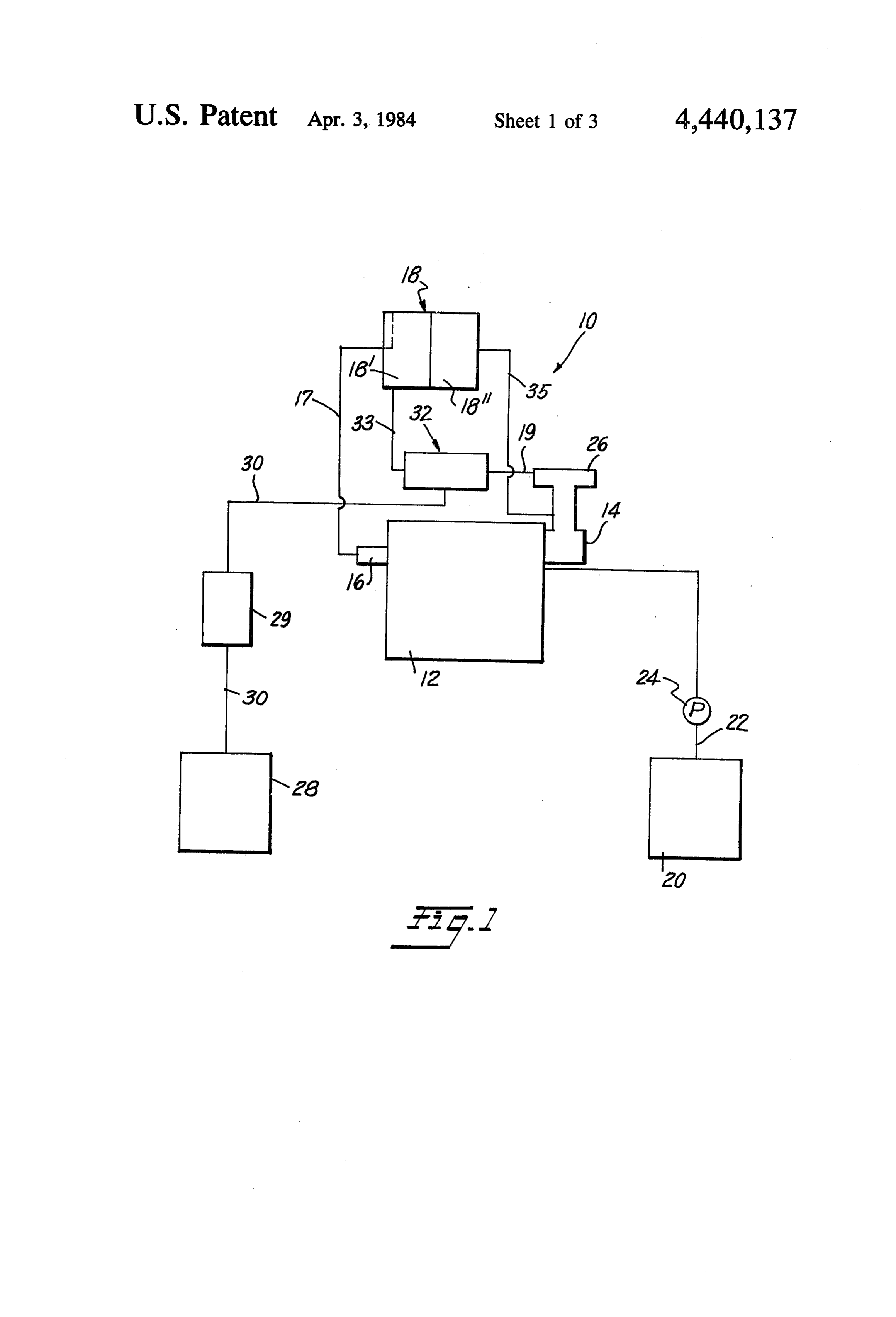
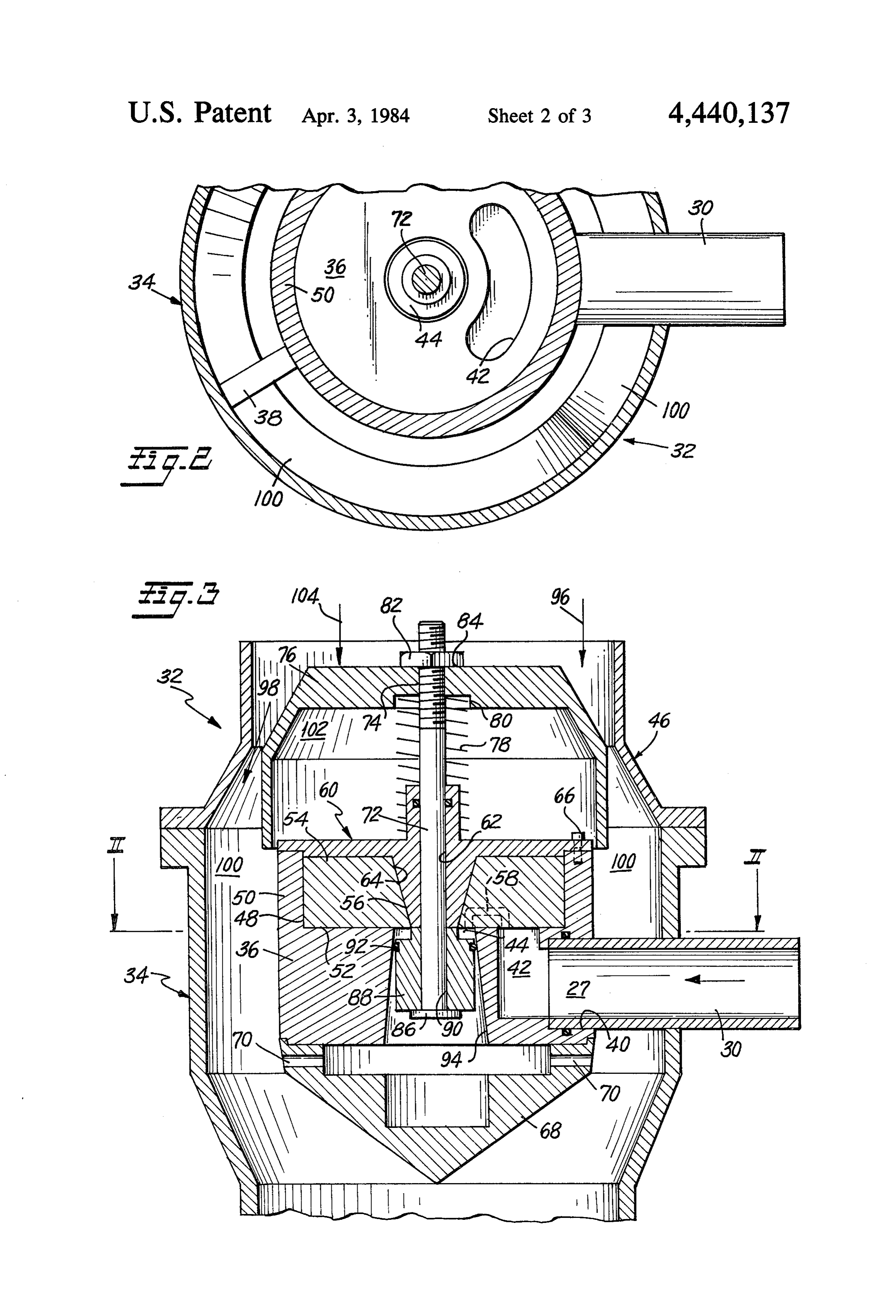
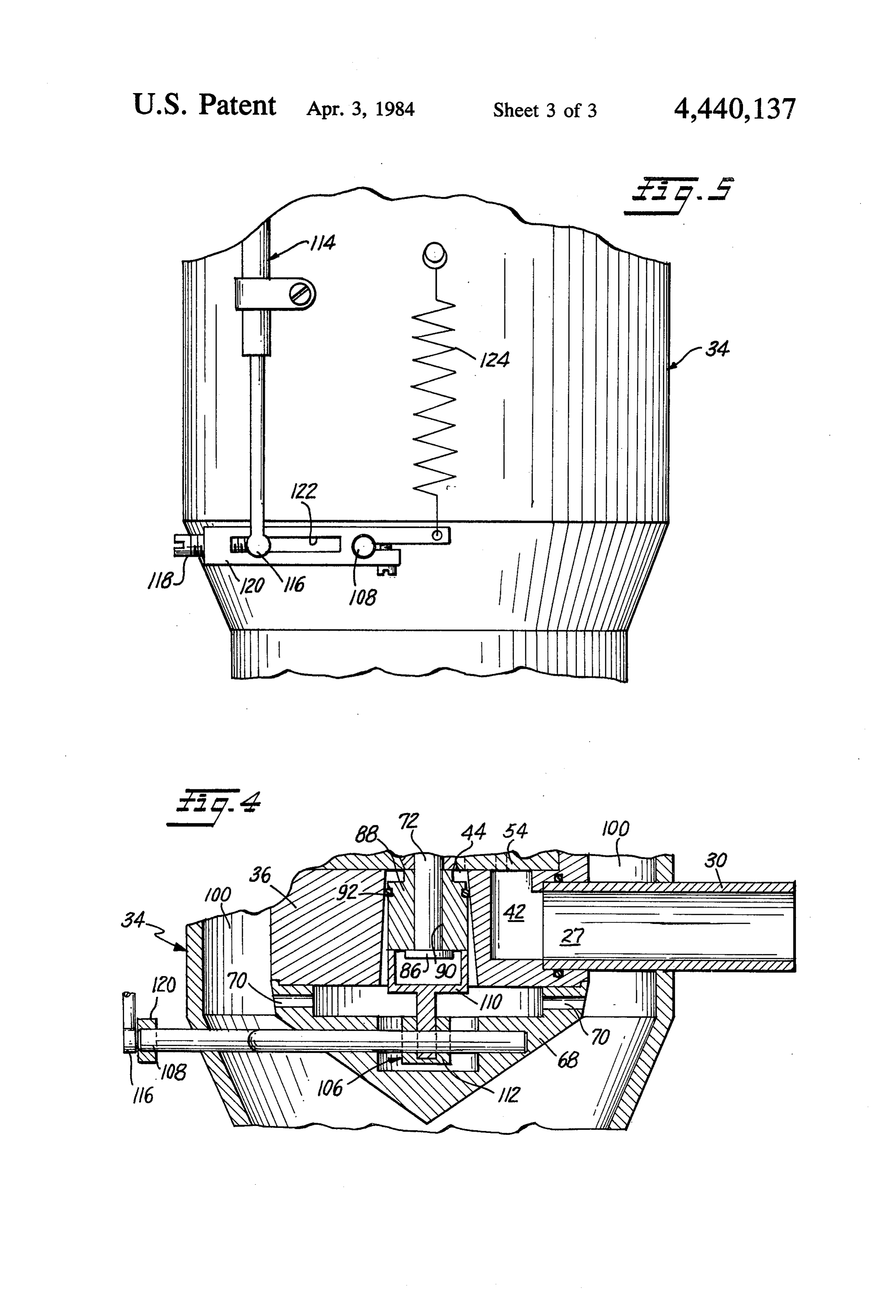
nation with a diesel powered internal combustion en gine. The device allows the use of lower cost propane BRIEF DESCRIPTION OF THE DRAWINGS or other gas fuel in combination with the use of diesel FIG. 1 is a schematic representation of the dual fuel fuel. It has been found that propane increases the effi 20 system according to the present invention; ciency of a diesel engine, thereby allowing a prospec FIG. 2 is a top view of the gas injection metering tive diesel engine purchaser to purchase a smaller en valve of the present invention;
gine to do substantially the same work as a large engine FIG. 3 is a side view, in cross-section, of the metering counterpart running on diesel fuel alone. Also, the addi tion of propane causes a more complete combustion of valve; FIG. 4 is a partial, side view, in cross-section, of an diesel fuel entering the engine. This has been noted by a 25 alternative embodiment of the present invention; and, marked drop in the exhaust temperature in a diesel FIG. 5 is a schematic representation of a control engine after propane has been injected and the throttle system for the embodiment shown in FIG. 4. has been reduced to the same torque as it was with a straight diesel. Due to the more complete combustion of DETALED DESCRIPTION OF THE the diesel fuel, pollution is greatly reduced by reducing 30 PREFERRED EMBODIMENT the amount of the unburned diesel fuel previously Reference numeral 10 indicates a schematic represen passed through the exhaust system. This is also an im tation portant ecological consideration. The valve unit, of the presentofinvention.
the dual fuel system as contemplated by the present invention, is designed to inject gas fuel into the intake manifold 14Internal combustion engine 12 has an intake air of a diesel. The unit is designed to meter the 35 nected between the and an exhaust manifold 16. Con manifolds 14-16, is a turbocharger gas in proportion to the air demanded by the engine. In one embodiment, the air demanded by the engine cre side 18 with an intake side 18' and a compression discharge ates a pressure differential across an inlet air flow re 18'. A supply tank 20 containing liquid fuel sponsive element of the gas injection valve so as to supplies the fuel to a fuel injection system (not shown) control the opening and closing of the valve so as to for injection to the combustion chambers (not shown) control the amount of gas injected into the internal via a conduit 22, and a pump 24. An air cleaner 26 is combustion engine. The element which is responsive to mounted on the engine in any well-known manner and the incoming air is disposed at one end of a cylindrical is adapted to deliver air so as to ensure the proper air/f. chamber within which is located a biasing means. The uel ratio for combustion within engine 12 and also, by incoming air to the internal combustion engine causes a 45 conduit 19 to the injection valve 32 of the present inven pressure drop in the chamber and, as the pressure falls in tion. A gas fuel supply (e.g., propane) is indicated at 28 the chamber, the atmospheric pressure creates a force and is connected by conduit 30 to a vaporizer regulator which compresses the spring and allows the air flow 29, for vaporizing the gas, and the gas fuel metering or responsive element to open until the tension of the bias control valve, of the present invention, indicated gener ing means equals the forces acting on the air reactor 50 ally at 32. The metering or control valve 32 is attached member due to incoming air flow. Due to the intercon so as to receive air demanded by the engine and, when nection of the valve, the air flow responsive element actuated, to transmit the air/gas vapor mixture to the controls the position of a gas valve which acts to meter turbocharger 18 via conduit 33. The turbocharger 18 is the incoming gas supply to the internal combustion driven by exhaust gas from the exhaust manifold 16 via engine. The higher the air flow, the more the gas valve 55 conduit 17 or, in the alternative, by any well-known is moved to an open position thereby allowing more gas manner. The compression side 18" supplies the mixture to enter the engine. The element responsive to the air to the intake manifold 14 via conduit 35. The unit 32 is flow may be adjustably positioned by means of a designed to meter the gas fuel in proportion to the air threaded engagement with a valve stem connected to demanded in accordance with engine speed as will be the gas valve. Accordingly, the gas fuel can be injected explained in further detail below. in response to varying engine speeds. FIG. 2 is a top sectional view taken along the lines A second aspect of the invention utilizes a direct II-II in FIG. 3. The housing casing is shown at 34 and mechanical connection between the gas valve and the supports a valve body 36 by a three-post mounting engine throttle control. In this concept, the gas valve is arrangement, one of which is shown at 38. The gas fuel held in a closed position until the cable is actuated by 65 inlet conduit 30 is received within an opening 40 of the the throttle control as the throttle is initially opened. As valve body 36. As shown, the body member 36 has a gas the throttle is moved to increase engine speed the cable entrance passage 42 for receiving the gas fuel supply is actuated, and a control arm imparts rotational move from the conduit 30. The duct 42 is fluidly connected, in 6 a manner to be explained later, with a central aperture arrow 96, and passes the air flow responsive member 76 44 in the valve body 36. in the direction of arrow 98 into the cylindrical cham The valve body unit 32, shown in FIG. 3, is contained ber 100. A lower pressure is created in chamber 100 due within a two-part casing 34, 46. The valve body assem to the pressure drop across member 76 caused by the bly 36 defines an L-shaped area, when viewed in cross force exerted by spring 78. Thus air is demanded by the section, which is defined by a vertically extending wall engine, incoming air flow causes a pressure drop in portion 50 and a horizontally extending ledge portion chamber 100 and chamber 102, respectively. As the 52. The L-shaped area 48 positions a guide block 54. pressure falls in chambers 100 and 102, the atmospheric The guide block 54 is provided with converging side pressure exerts a force in the direction of arrow 104 and walls 56 which define a centrally located, circular aper 10 compresses spring 78 as member 76 is forced in the ture. The guide block 54 also defines a plurality of gas direction of arrow 104. Air flow responsive element 76 passages, one of which is shown at 58, which allows the will open until a balance between an engine air demand gas fuel to communicate between gas entrance passage plus the spring tension in spring 78 equals the incoming 42 and the central body aperture 44 of the valve body atmospheric pressure. The position of the member 76 assembly 36. A valve cover assembly 60 is provided 15 controls the position of the gas valve element 88. Gas with a central aperture 62 and converging side walls 64. valve 88 seals off the gas passage completely by an The side walls 64 and 56, of the cover and guide block, O-ring 92. As the engine demands more air, the valve 88 respectively, are mounted in flush engagement with is forced down the diverging walls 94 of the valve body each other. The valve cover 60 may be secured to the 36 by pressure differential forces. The further the valve vertically extending wall portions 50 of the valve body 20 88 is forced down the divering passage, the more gas is 36, by any known manner which ensures a tight seal. allowed to pass from the gas entrance passage 27, For purposes of illustration, a bolt attachment is shown through the gas passageways 58, to the gas inlet area 44 at 66. of the valve body 36. The gas vapors enter the conduit Secured to the base of the valve body assembly 36 is 33 through the orifices 70. After compression in the a cone-shaped orifice housing 68. As with the cover 25 turbocharger 18, the mixture is introduced into the assembly 60, the orifice housing 68 may be secured to intake manifold 14. As previously discussed, the relative the body assembly 36 by a series of screws, not shown, positioning of the air flow responsive member 76 can be arranged around the periphery of the housing 68. This changed on rod 72 by loosening the fastening means 82 arrangement would be similar to the attachment means so as to change the relative position of the member 76 66 for the cover assembly 60. As will be described later, 30 with respect to the casing section 46. Accordingly, this orifices 70 are provided for directing the gas fuel from changes the engine rpm when the gas injection is to the central aperture 44 into the air stream of the internal start entering the airstream. Accordingly, it is to be combustion engine 12. understood that the system has two modes of operation, Slidably mounted within the cover assembly 60 is a i.e., liquid fuel alone or a combination of liquid fuel and rigid rod connector 72. As shown in FIG. 3, one end of 35 gaseous fuel.
the rod 72 is threadedly engaged at 74 with air flow FIG. 4 discloses an alternate embodiment of the gas responsive member 76. A spring member 78 biases the inlet valve 32 disclosed in FIG. 3.
member 76 away from the valve cover element 60. The The embodiment of FIG. 4 relates essential to the spring 78 is concentric to the rod 72 and one end is mechanism by which valve 88 is operated and con seated within member 76 within a shoulder 80. The 40 trolled. Accordingly, like elements of FIG. 4 will be other end of the spring 78 is seated against the valve denoted by the same reference numerals as set forth in cover 60. An adjusting member 82 is threadedly en the disclosure of FIG. 3. In this embodiment, the gas gaged with the rod 72 and contacts the member 76 at 84. inlet valve element 88 is allowed to slide freely on the The adjusting means 82 allows the relative position of rod 72 forming a lost motion connection, in that rod 72 the air flow responsive member 76 to be changed on rod 45 can move one way (down) without moving valve ele 72 by loosening the adjustment means 82 and threading ment 88, but will positively drive the valve element the member 76 up or down on rod 72. This changes the towards a closed position when it moves the other way relative position of the member 76 with respect to the (up). A stop element 86 is provided on the end of the casing member 46. rod 72 to effect positive closing motion. A crank lever At the opposite end of the threaded section 74 of the 50 assembly, for controlling the opening and closing of the rod 72 is a stop member 86. The stop member 86 sup aperture 44 by the valve element 88, is indicated gener ports and fixedly positions valve element 88 comprising ally at 106. The assembly 106 is rotationally attached to a rectilinearly movable plug in a tapered bore 94. The the shaft 108 which, in turn, is operatively connected to valve element 88 has a central aperture 90 to allow the the engine throttle in a manner to be explained below. valve stem rod 72 to pass therethrough. Circumferen 55 The crank assembly and shaft 106, 108, respectively, tially surrounding the valve element 88 at its topmost are positioned within the cone-shaped orifice housing portion of largest radius is an O-ring 92. When the valve 68. The assembly 106 consists of a yoke member 110 88 is in its closed position, i.e., when it does not allow fixedly attached to the shaft 108 and a stop member 112. gas to pass into the air stream of the engine, the O-ring The yoke assembly 110 is engaged, in cam and follower 92 sealingly engages with the diverging side walls of the relationship with the bottom surface area of the valve bore 94. element 88 so as to control its reciprocating movement In operation, the unit 32 is designed to inject gas that within the aperture 44 of the valve body element 36 as has been vaporized into the intake manifold of an inter defined by the diverging wall portions 94. The rota nal combustion engine, and in the case contemplated by tional movement of the shaft 108 is controlled by a cable the present invention, a diesel engine. The unit is de 65 114 connected to the engine throttle (not shown). An signed to meter the gas in proportion to the air de end 16, of the cable 114, is attached to the crank lever manded by the engine as determined by throttle position assembly 106 by an adjustment member 118. The adjust (engine speed). Air enters the unit 32 in the direction of ment member 118 is threadedly engaged with a control 7 arm 120. The control arm 120 has a slot 122 which position independently from said biasing means; allows the cable end 116 to be attached to the screw movement of said air flow responsive member 118. Further, the slot 122 determines the maximum and being unrestricted by said valve element control minimum rotational movement of shaft 108 and hence, e2S.
the maximum and minimum reciprocating travel of the 5 2. A control valve as claimed in claim 1, said valve valve 88, which in turn determines the percentage of element connected to said air flow responsive member gas entering into the airstream of the engine. A spring by a lost motion connection that permits said valve 124 functions as the return spring for the crank assem element to move towards an open position when said air bly 106. This spring 124 holds the gas valve closed responsive member is deflected, but positively drives unless the throttle of the engine is depressed. O the valve towards a closed position when said air re In operation, the valve element 88 is held in a closed sponsive member is moved into its undeflected position. position by the spring 124 until the cable 114 is actuated 3. A control valve as claimed in claim 2, said lost by the throttle, not shown. Because of the lost motion motion connection comprising a rigid rod connector connection, movement of the rod 72 and the air reaction extending between said air flow responsive member and member 76 is unrestricted, and these elements can still 15 said valve element, with said rod connector engaging move in response to air flow pressure. Once the cable said valve element so that the rod connector can move 114 is actuated, the crank arm 120 rotates shaft 108 and independently of the valve element when the rod con with it, yoke 110. The rotational movement of the yoke nector moves in one direction in response to deflection 110 allows the valve element 88 to move to an open of said air responsive member, but directly engages and position and an amount of gas, determined by the ad 20 carries the valve element with said rod connector when justment of screw 118, enters the turbocharger 18 and the rod connector is moved in the reverse direction, at the engine 12, as previously discussed. After the throttle least as said air responsive member approaches its unde has moved beyond a low throttle position near idle, of flected, at-rest position.
course, yoke 110 is moved by the throttle cable and 4. A control valve as claimed in claim 3, said air flow valve element 88 moves in accordance with the fluid 25 responsive member and rod connector together for pressures acting on it to seat against the stop 86, at simultaneous movement in a rectilinear direction within which time the valve element follows the motion of rod said duct when said air flow responsive member is de 72 until or unless the yoke 110 moves the valve element flected; said valve element likewise being movable rec towards the closed position independently of the air tilinearly between open and closed positions; said valve flow responsive member as the throttle moves towards 30 element mounted on and supported by said rod through its idle position. a sliding connection; said rod having a laterally en While the invention has been described in terms of larged valve element engaging means adjacent its distal certain preferred embodiments, the skilled worker in end; said valve element engaging means retaining said the art will recognize that there are various changes, valve element assembled to said rod and comprising omissions, modifications, and substitutions that may be 35 means for directly engaging and carrying the valve made without departing from the spirit of the invention. element when the rod is moved in said reverse direction Accordingly, it is intended that the scope of the present by limiting the endwise sliding motion of said valve invention be limited solely by that of the following element along said rod.
claims. 5. A control valve as claimed in claim 2, said valve We claim: element control means comprising movable means se 1. A control valve for a gas fuel supply to an internal cured to said housing and actuatable from the exterior combustion engine including an air intake conduit of the housing.
means comprising: 6. A control valve as claimed in claim 3, said valve a valve housing including an air duct extending element control means including means for resiliently through the housing and having inlet and outlet 45 biasing said valve control means in a direction to urge ends, the housing arranged to be connected to said said valve element towards a closed position. air intake conduit means so that the outlet end of 7. A control valve as claimed in claim 6, said valve said air duct is in communication with said conduit; element comprising a rectilinearly movable plug in an a movable air flow responsive member in said duct elongated tapered valve port that is in communication arranged to be deflected in a first direction by 50 with said gas fuel inlet at one end and said air duct at its forces resulting from air flowing through said duct other end, and said valve element control means con towards the outlet end thereof; prising a cam member directly engageable with said means for resiliently biasing said air flow responsive valve element, and means for moving said cam element; member in a direction opposite to said first direc movement of said cam means in a single direction caus tion of deflection towards a nondeflected position; 55 ing progressive rectilinear movement of said valve ele a gas fuel inlet into the housing; ment towards a closed position. a gas fuel passageway in the housing providing com 8. A control valve as claimed in claim 2, including an munication between said gas fuel inlet and said air internal combustion engine having an air intake supply duct at a point between said air flow responsive conduit and a throttle means for controlling engine member and the outlet end of said duct; speed and power, said throttle means movable between a valve element for controlling gas fuel flow through open and closed positions, said control valve connected said passageway, said valve element movable be to said conduit so that substantially all of the engine tween closed and open positions in response to the intake air passes through said duct, said valve element movement of said air flow responsive member be control means comprising a connection between said tween undeflected and deflected positions, respec 65 throttle means and said valve element arranged to cause tively; and said valve element to be urged towards a closed position valve element control means for moving said valve when said throttle means is moved towards a closed element towards and maintaining same at a closed position.
Page 8scan →
9. A control valve as claimed in claim 8, said connec passes through the duct of said control valve and said tion including means for varying the relationship be air intake supply conduit.
tween input throttle motion and output valve element 11. A control valve as claimed in claim 10, including control motion. an intake air pressurizing means controllable in response 10. A control valve as claimed in claim 2, including a to engine speed in said air intake supply conduit be diesel-type internal combustion engine having an air ports. tween said control valve and said engine air intake intake supply conduit in communication with air intake 12. A control valve as claimed in claim 11, said air ports of said engine, and an injector-type liquid fuel pressurizing means comprising an engine exhaust gas supply system; said control valve connected to said air 10 driven turbocharger.
intake supply conduit so that all of the engine intake air k 2k 2k xk sk
Provenance
- Collection
- Patents citing this work
- Pages
- 8
- Method
- pdftotext (the PDF's own text layer) + pdftoppm 300dpi page scans
- Patent office record
- patents.google.com →
- Source
- Google Patents citing-documents table
- Assignee
- Propane Carburetion Systems, Inc.
- Published
- 1984-04-03
- Transcribed from
- patentimages.storage.googleapis.com →