

patent · US4440155A
Solar concentrating lens and receiver
3 April 1984
Text
Page 1bibliographic recordscan →
.. .. .. . ii. 52 is
4. f3 4. XR & & A. . . . . S.
United States Patent (19)
Maloof et al.
54). SOLAR CONCENTRATING LENS AND
RECEIVER
75 Inventors: Ralph P. Maloof, Calabasa; Roger R.
Reynolds, Jr., Costa Mesa, both of
Calif.
73 Assignee: Repla & Taylor, Inc., Santa Ana,
51 Int. Cl. ................................................. F24, 3/02 52 U.S. Cl. .................................... : E;
3,884,217 5/1975 Wartes ................................ 126/438 4,114,597 9/1978 Erb ...................................... 126/448 4,289,118 9/1981 Stark ................................... 126/440
4,323,052 4/1982 Stark ................................... 126/440
FOREIGN PATENT DOCUMENTS
56-48101 1/1981 Japan ................................... 126/440 Primary Examiner-James C. Yeung
Attorney, Agent, or Firm-William H. Maxwell
A solar concentrating lens and receiver operating on azimuth and altitude axes according to the position of the sun and characterized by an array of elongated transparentconfiguration prism-lens slas spacedwith feventiation and for a reflective base, eachbothof refractive and reflective focus of heat rays through a narrow slot into a receiver and onto an absorber at a focal plane where heat absorption is into a fluid media within an insulated and vacuumized internally reflec tive chamber.
22 Claims, 11 Drawing Figures
Drawings
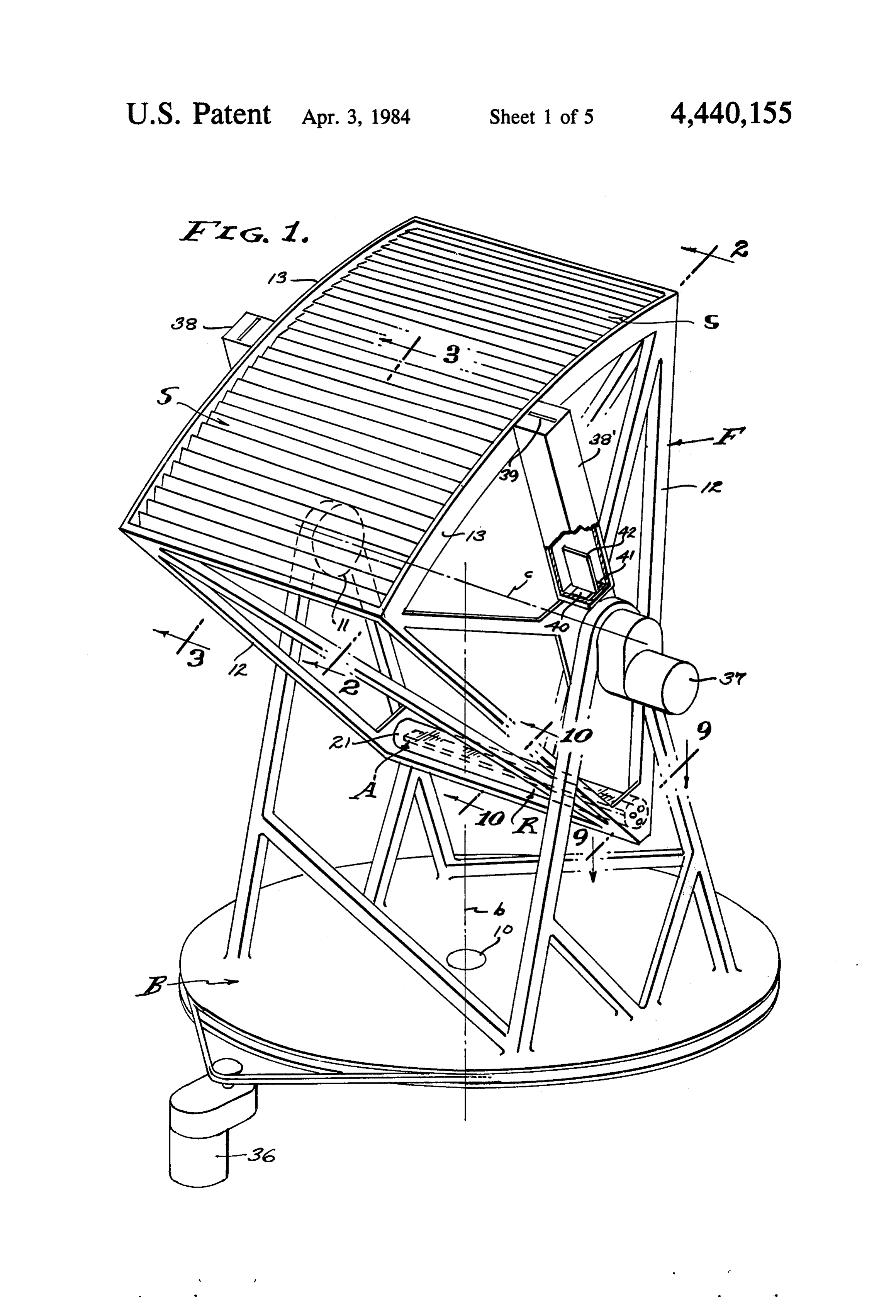
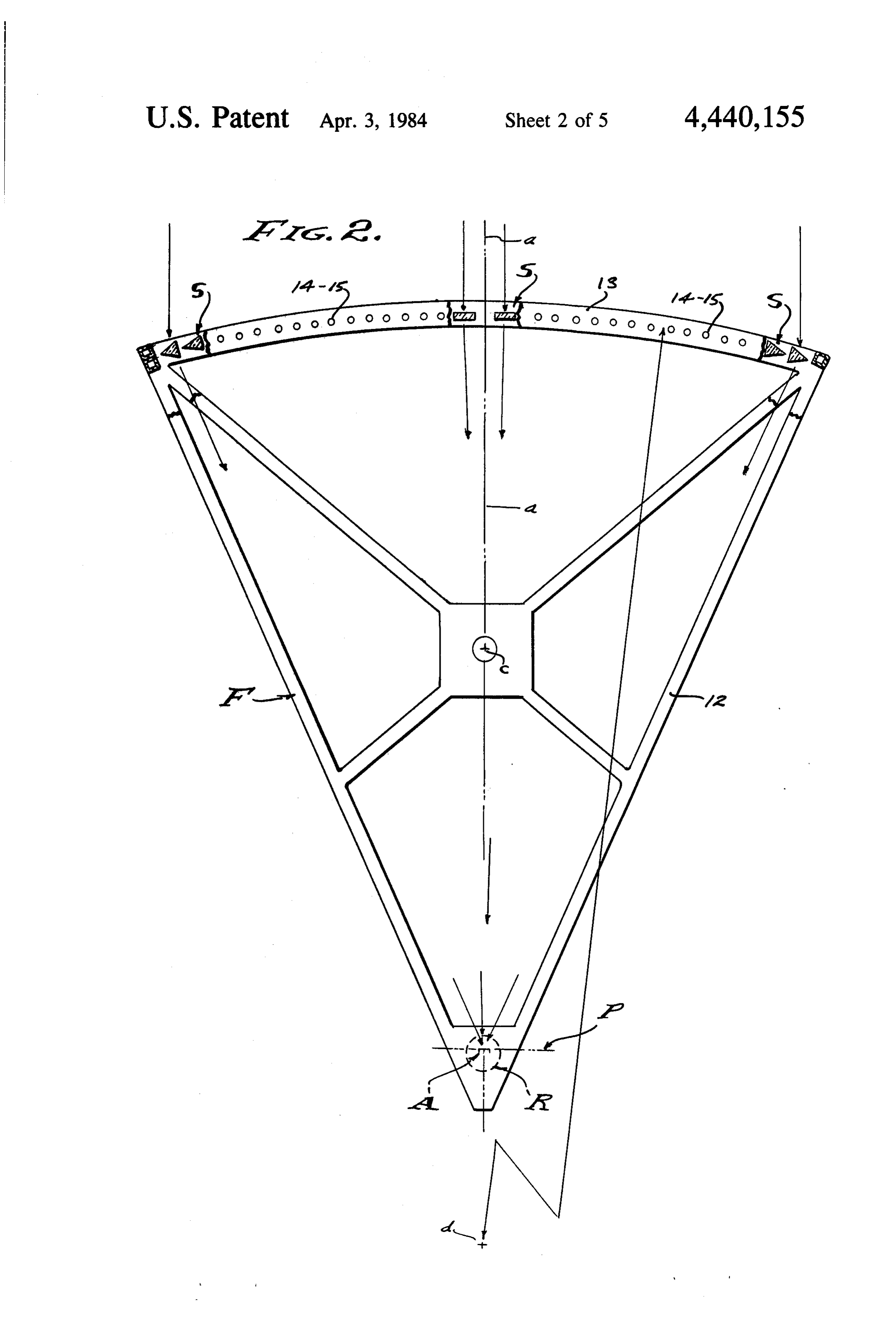
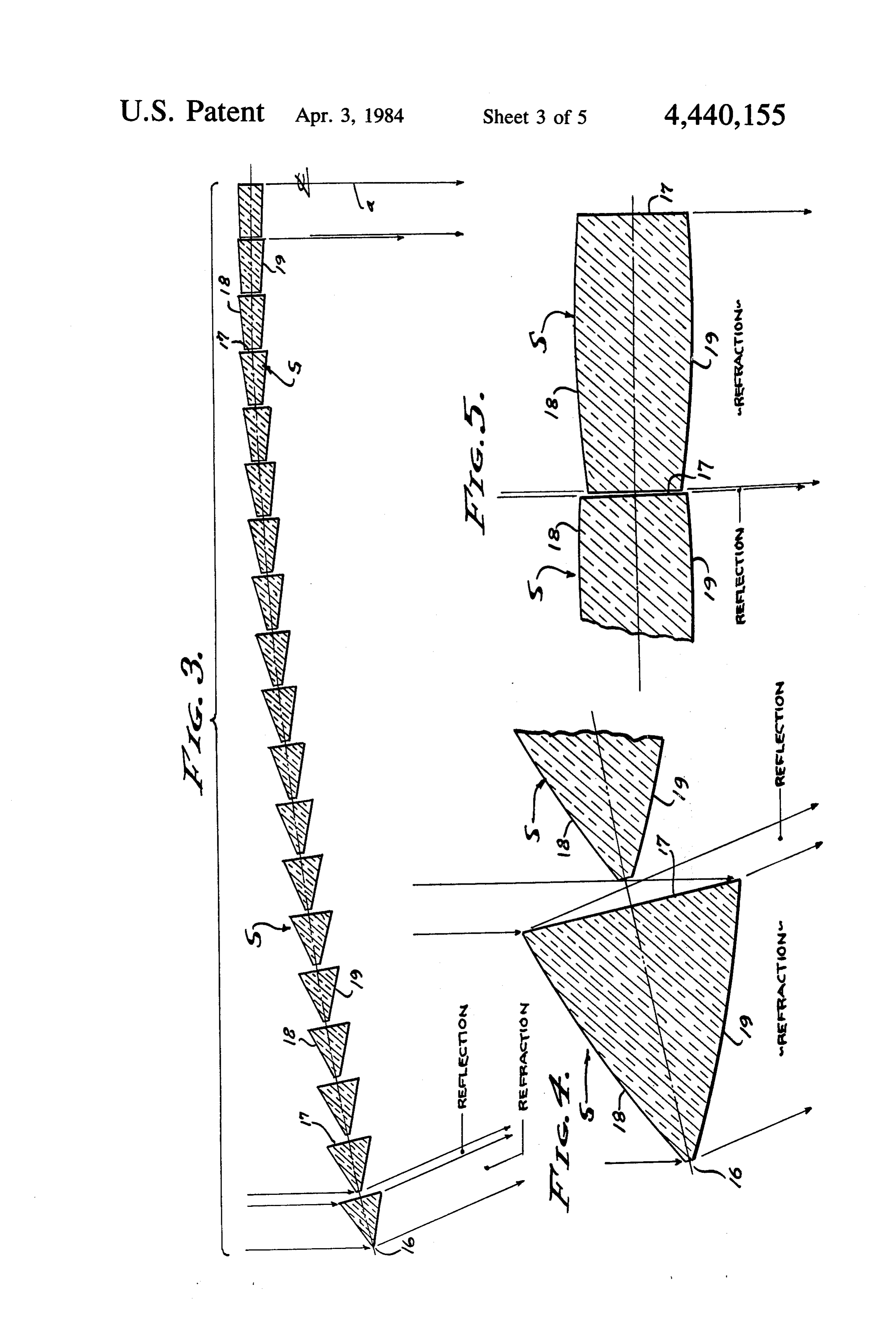
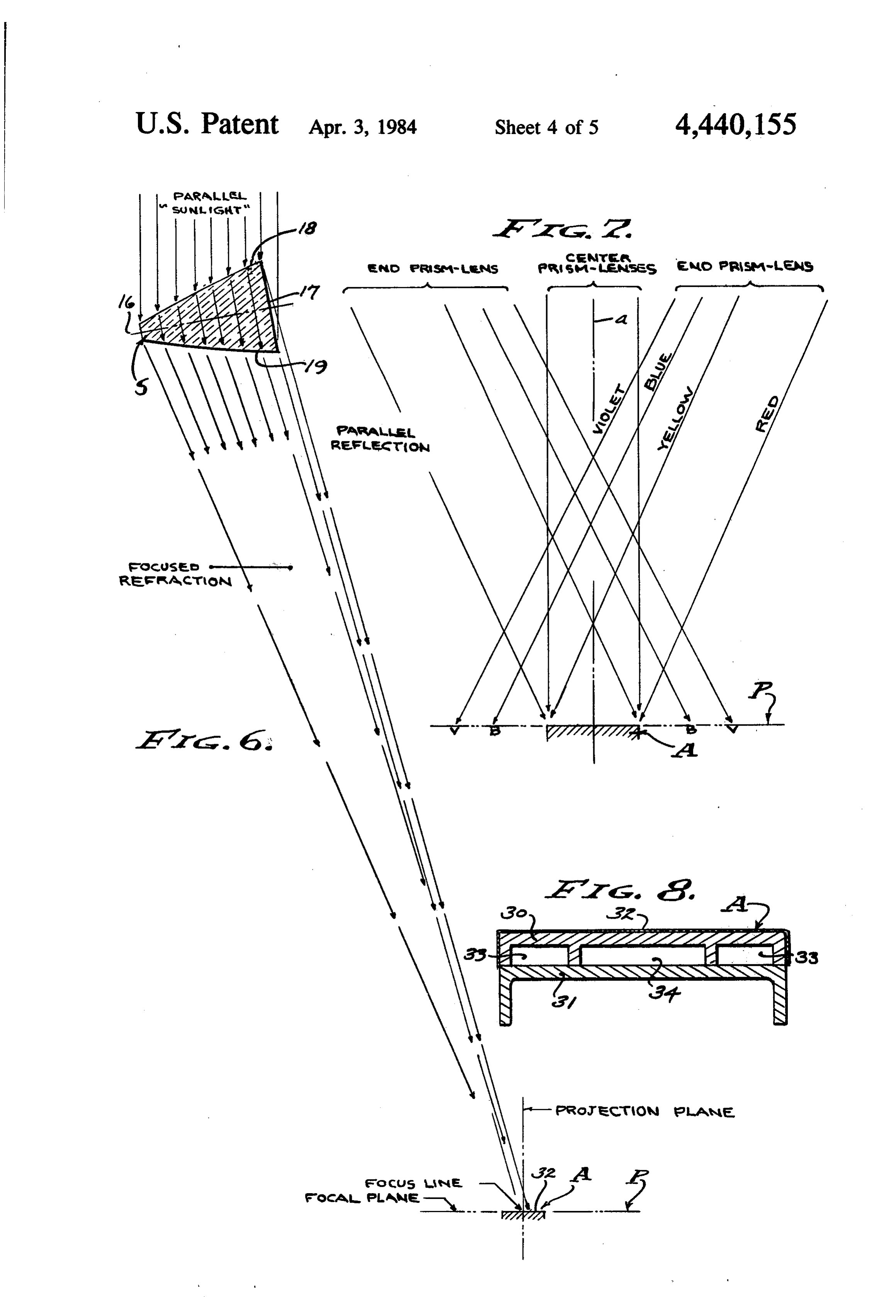
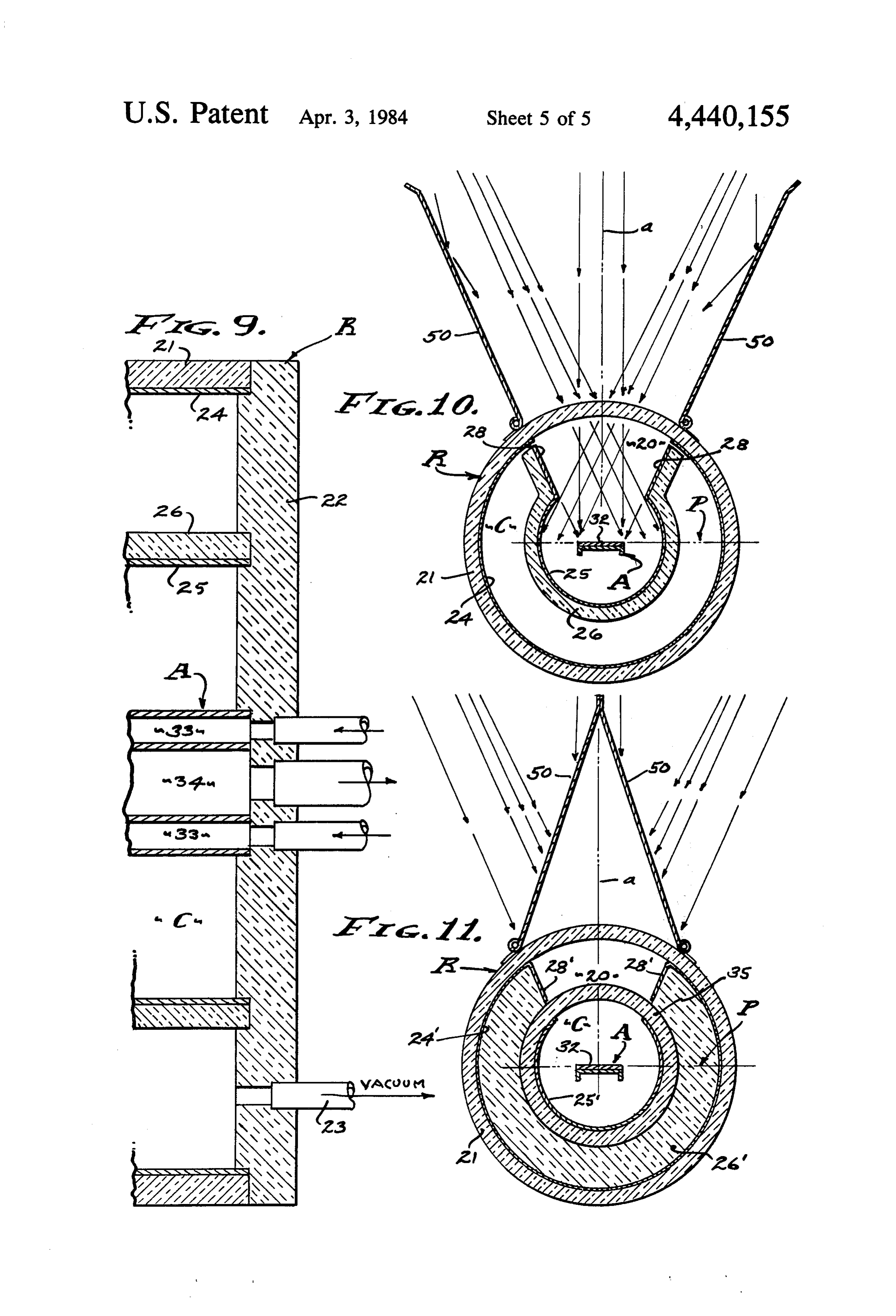
FIG. 4 is an enlarged fragmentary view showing the carried on said mean radius from a center of arc d. In a reduction to practice of this invention, there are nine prism-lens of FIG. 3 having the greatest refraction and teenslats
FIG. 8 is an enlarged detailed sectional view of the ture 20 is provided to pass these sheets of light from multiple prism-lenses and into the receiver R, in prac absorber.
Page 2drawing sheetscan →
Page 3drawing sheetscan →
Page 4drawing sheetscan →
Page 5drawing sheetscan →
Page 6drawing sheetscan →
Page 7scan →
the opposite ends of the array, the array being symmet
SOLAR CONCENTRATING LENS AND RECEIVER rical about a central projection plane. Efficiency of insolation requires minimized attenua
BACKGROUND tion of incoming solar light and reduction of re-radia Solar radiation is a prime source of energy, collected tion. Accordingly, it is an object of this invention to provide an efficient prism-lens array and efficient re by means referred to generally as "insolation', it being ceiver-absorber a general object of this invention to efficiently capture ployed for theircombination.
Lenses of acrylic are em inch thickness) attenua heat energy from the sun rays by means of optical con tion, and the "slot' window receiver is internally reflec centration and fluid media absorption. Solar concentra 10 tive and vacuumized and/or internally insulated. tion is of primary concern, it being the heat rays which The "prism-lens and slot absorber' combination of are to be concentrated at a focal plane with the least the present invention is a linear apparatus, in that the loss. The geometric concentration is to be, for example, slats and slot receiver-absorber are elongated for the one hundred to one, whereby 500-700' F. fluid is pro reception of large quantities of solar light concentrated duced from the absorber at pressure up to, for example, 5 upon a restricted focal plane area. As shown, the prism 700-800 p.s.i. lenses and receiver-absorber are disposed in parallel Heretofore, lens and mirror systems for insolation relation, so that light from the entire area of the slat have been cumbersome and space consuming, and the array is projected through the slot and onto the focal receivers and absorbers have been wasteful of incoming plane target. In practice, the concentration of solar light light. That is, very large areas have been required for 20 is within a feasible range of use, for example within the solar collection, and there has been dispersion of other aforesaid range of 500-700' F., and distributed along wise useful light ahead of and at the absorber target. It the 'slot' window and evenly upon the focal plane and is acknowledged that the objective area is a controlling absorber elements, whereby common commercially factor which determines the quantity of light to be available materials are useable in constructing the re collected and subsequently concentrated, and it is this 25 ceiver and its supporting structure. Only at the focal area which is minimized by the present invention by plane is any of the apparatus subjected to high heat, and employing a "prism-lens' objective array having a only to that structure which is in close proximity to the number of advantageous features as hereinafter de concentrated light.
scribed. The optical concentration of light provided by Solar tracking is to be considered, it being an object the prism-lens array is focused upon a plane within the 30 of this invention to simplify tracking with single or a receiver, entering therein through a narrow slot-shaped dual axis system responsive to the azimuth and at least window, to be captured within the internally reflective the altitude positions of the sun, regardless of the lati confines of the vacuumized receiver and concentrated lens tude and longitude placement of the apparatus. The slat onto the absorber, as will be described. array herein disclosed is particularly adapted to The "prism-lens' array which characterizes the solar 35 either single or dual axis tracking, it being a simple light objective area of the present inventive concept is matter to track each function of the sun's position comprised of a multiplicity of linear light concentrators within the resolution desired, as will be described. Ac of slat configuration. It is an object of this invention to cordingly, there are means that separately determine or concentrate light by focusing it upon the absorber detect movement of the sun's azimuth and/or altitude, plane, utilizing each slat as a lens and for example a and which actuate drive motors that position the appa ratus within the accuracy required for projection of all convex lens having camber that focuses onto the ab incoming solar light through the "slot' window and sorber focal plane. It is the infrared heat rays which onto the absorber focal plane within the receiver. have greatest heat value and which are of longer wave length focused upon said absorber focal plane, while the 45 SUMMARY OF INVENTION ultraviolet light at the opposite end of the spectrum and of shorter wave length is of less effective heat value and tion of heat into arelates
This invention to insolation and to the absorp is focused short of said focal plane. In accordance with concentration of heat rays media, transfer by means of optical into the confines of a re this invention, it is an object to concentrate the useful ceiver. The optical system employed herein is charac solar light and especially the Yellow to Red light, Blue 50 terized by a multiplicity of transparent slats that are to Violet light being marginally useful. Therefore, the spaced for ventilation and which are of prismatic lens receiver of this invention is characterized by its "slot" shape for refraction and focus of heat rays upon a focal window through which the useful solar light is concen plane where absorption is to occur. Each "prism-lens' trated and focused upon the absorber focal plane. A is of prism-like cross section having a reflective first feature is that each slat is a prism-lens focused upon the 55 surface base that also focuses heat rays passing between absorber focal plane. spaced slats and onto the said focal plane where absorp The slat prism-lens array as it is disclosed herein is tion is to occur. The array of slats is carried by spaced similar to a Fresnel Lens, and accordingly is a weight beams cambered so as to accommodate the reflective saving feature. However, this slat prism-lens array must light path between prism-lens slats, as they are displaced be exposed to the natural environment, namely the wind 60 from a central projection plane extending to the center element of the atmosphere, and it is wind gusts to which line of the focal plane. The outermost prism-lens slat is the apparatus is subjected and to which it must be struc of full isosceles cross section having an apex and with its turally resistant. Accordingly, the slat elements of this base facing said projection plane, while each progres lens array are spaced for ventilation, but without sacri sively inward prism-lens slat is of reduced apex angle fice with respect to light collection efficiency, the base 65 and has its apex truncated more severely and its base of each prism-lens cross section being disposed so as to diminished, whereby mass is minimized while retaining reflect light through said space and onto the focal plane sufficient strength. Each prism-lens is of a cross sec of the absorber. Note that this spacing increases toward tional configuration involving a precise angle, width 8 and base depth that will focus a full band of heat rays parallel relation with the incoming light. Accordingly, through the "slot' of the receiver and onto the focal there is a base B that revolves on bearings 10 disposed plane of the absorber. The receiver is characterized by on vertical axis b and carries spaced trunnions 11 on the slot-shaped window through which the heat rays of horizontal axis c. The tracking optical array and receiv solar light are concentrated onto a heat absorption tar 5 er-absorber combination is carried by a frame Fjour get at the focal plane. A feature is the narrowness of the naled on and within the spaced trunnions 11, a space "slot' and the openness of the vacuumized reflective frame comprised of spaced side trusses 12, or the like, interior of the absorber where heat is taken into a fluid between which transparent slats S and a receiver R heat transfer media circulating through the absorber. extend. The absorber A is centered within the receiver This prism-lens array and absorber combination is jour 10 R at the lower apex of the frame trusses, and the slats S naled on a vertical azimuth axis and at least on a hori occupy the upper widened objective end of the frame zontal altitude axis, or compound axes combining the trusses disposed toward the incoming sunlight. The two, upon which axes or axis it is directed toward the frame F is rigid and openly supports the slats S for incoming and parallel sunlight. Tracking is by means of ventilation, and all of which is free to revolve on the a programmed clock means or by means of light sensors 5 horizontal altitude axis c.
that detect position of the sun and actuate motor means The objective ends of the spaced trusses 12 are com to make corrective movements on said vertical and/or prised of like or identical outwardly cambered beams 13 horizontal axes, all in order to maintain the projection arcuately formed about a center d substantially below a plane coincidental with and parallel to the incoming focal plane P, as shown. In practice, the radius to d is sunlight, within a prescribed degree of accuracy or 20 approximately twice that of the radius to the focal plane resolution. Any number of these units of apparatus can P, as determined by the positioning of adjacent slats S be arranged and used together as a multiple array.
The various objects and features of this invention will and in their revolvement that places their reflective bases position to redirect the incoming sunlight through the be fully understood from the following detailed descrip intermediate spaces and to the target. The slats Sextend tion of the typical preferred forms and applications between the beams and are adjustably secured thereto thereof, throughout which description reference is by pivots 14. The individual slats S are set into proper made to the accompanying drawings, in which: rotative position parallel with the centerline of focal FIG. 1 is a perspective view of a Solar Concentrating plane P as by means of lock nuts 15 at said pivots 14. Lens and Receiver embodying the features of the pres The frame, beam and slat array are symmetrically dis ent invention. " . 30 posed
FIG. 2 is an enlarged view of the frame, lens array parallel one withabout the projection plane a, the slats S being and receiver, taken as indicated by line 2-2 on FIG. 1. plane a. the other and with the projection FIG. 3 is an enlarged detailed sectional view showing The slat S array carried by the arcuately cambered half of the prism-lens array and taken as indicated by beams 13 is semi-cylindrical, with the individual slats S line 3-3 on FIG. 1. 35
FIG. 4 is an enlarged fragmentary view showing the carried on said mean radius from a center of arc d. In a reduction to practice of this invention, there are nine prism-lens of FIG. 3 having the greatest refraction and teenslats
S at each side of the projection plane a, a total of thirty eight slats S. The radius to arc center d is
FIG. 5 is an enlarged fragmentary view showing the approximately prism-lens of FIG. 3 having the least refraction and 40 slat S to the absorber 260 inches while the radius from each reflection angles. A is optimum. Assuming the slats FIG. 6 is an enlarged sectional view of an intermedi S to be flat faced prisms, a sheet of light substantially ate prism-lens and absorber, showing the focus to a line equal to the width of the prism will be projected, for at the focal plane. example as shown a width of 3.03 inches. However, it is FIG. 7 is a diagramatic view showing the concentra 45 effectpreferred that the prisms are cambered to have a lens tion of heat rays onto the absorber, and the colder rays terlinethat focuses the incoming sunlight onto the cen of the absorber A target. Accordingly, an aper to the sides thereof.
FIG. 8 is an enlarged detailed sectional view of the ture 20 is provided to pass these sheets of light from multiple prism-lenses and into the receiver R, in prac absorber.
FIG. 9 is an enlarged detailed plan sectional view 50 tice a 50 slot opening in the receiver body which in a through the end mounting of the receiver-absorber and reduction to practice of this invention is six inches in taken as indicated by line 9-9 on FIG. 1. diameter, and for example with a one inch absorber FIG. 10 is an enlarged transverse sectional view of widened to one and a quarter inches so as to accommo the open receiver and taken as indicated by line 10-10 date stray light. These dimensional proportions are on FIG. 1, and, 55 significant as related to the slat spacing for ventilation FIG. 11 is a view similar to FIG. 10 showing the and for reflection off of the bases 17 and projection of receiver closed and with a modified form of insulation. all light onto the focal plane. Each slat S is of basic prism cross section with its
PREFERRED EMBODIMENT apex 16 disposed outwardly from the projection plane a, Referring now to the drawings, there is a projection 60 and with its base 17 disposed inwardly toward the pro plane a that is to be maintained parallel with the incom jection plane a. Each slat S is of isosceles cross section ing sunlight, within a prescribed degree of accuracy. In with like or identical sides 18 and 19 extending inwardly order to do so, there is a vertically disposed azimuth from the apex 16, and the base 17 is disposed at an angle axis b and at least a horizontally disposed altitude axis c. that reflects incoming parallel sunlight in continuing By setting or revolving the apparatus about axis b the 65 parallel relation onto the focal plane P. This slat cross axis c is brought substantially or exactly normal to the section is prismatic and provides for refraction of light azimuth position of the sun, and by revolving the appa transmitted through the sides 18 and 19, and provides ratus about axis c the projection plane a is brought into for reflection of light striking the base 17.
Page 9scan →
Each prism cross section of a slat S is precisely a divergence of light from the longer infrared to the formed to have an apex angle adapted to project a sheet shorter ultraviolet rays. Lens focus is the result of bend of light totally entering the aperture 20 slot, varying ing the light. In practice and with the reduction to prac from 45 at the outermost slats S, to 2.7 at the inner tice disclosed herein, one or both sides 18 and 19 is most slats S. The 45 maximum is chosen for reasonable 5 cambered as they are shown and formed to an approxi light transmission efficiency of the prisms, limiting at mate 190 inch radius so as to have a focal length of tenuation to approximately 10%. Also, each slat S is approximately 132 inches with yellow light. Since it is precisely formed to have a truncated apex adapted to heat range light which is to be collected by absorption, enable strengthening of the slats. S by separating the it is the yellow to infrared rays which are sought to be sides 18 and 19. In practice, the sides 18 and 19 are 10 captured, and accordingly it is this range of longer light separated so that all slats Shave approximately the same waves which are focused onto the centerline of the cross sectional area, for rigidity as they extend between absorber A by the prism-lens slats S of the present in the beams 13. Accordingly, the apex truncation and vention. Therefore, it will be seen firstly, that a multi base 17 dimensions vary with the result that the remain plicity of sheets of substantially parallel incoming sun ing altitude of the prism slats S, from truncation face to 15 light are turned by the prismatic refraction of each slat base 17, varies for example from 2.81 inches at the out S to be dominated by the yellow to infrared heat range ermost prism slats S, to 3.03 inches at the innermost rays; and secondly, that this heat range of light rays is prism slats S. These dimensions determine the spacing inwardly focused by the convexly cambered sides 18 of adjacent prism slats S, whereby each reflective base and 19 to concentrate toward the centerline of the ab 17 is entirely exposed to all sunlight passing between 20 sorber A at focal plane P.
adjacent slats. . . . . .. . . . The phenomenon of dispersion is produced by refrac Structurally, the slats S. of prism cross section are tion (not by reflection) and results in a separation or made of a plastic material such as "Lucite' as manufac divergence of light rays from the focus line which is at tured by Dupont, a high quality cast optical acrylic of the centerline of the focal plane P. Therefore, and de low attenuation (8% per inch of thickness) having an 25 spite the focal length of the convexly cambered sides 18 index of refraction of 1.49 and a light transmission of and 19, dispersion causes some spreading of the focused 92%. A feature therefor is the light weight of the plastic light rays. Consequently with the present invention, having a specific gravity of 1.19, the slats being of slen there is a concentration of heat rays toward the center der cross section adapted to remain straight due to ri line of focal plane P, the centerline through which the gidity of the plastic material. Thermal expansion and 30 projection plane a passes. It is at this centerline of the contraction has little or no adverse effect on the slats S focal plane P that the highest heat concentration is and their ability to refract and to reflect light, despite developed.
the large objective areas and intense sunlight that may The receiver R and absorber A comprise an insola be involved and concentrated thereby, due to their tion device that collects the heat of absorption into a separation and individual structural integrity and resis 35 heat transfer fluid media, by which heat energy is trans tance to destruction. .. . . ... . .. ported for useful purposes. The array of cambered slats In accordance with this invention, the rotated posi S results in a narrow concentration of heat range light tion of each prism slat S simultaneously adjusts both the onto the focal plane P and embracing the centerline of refractive and reflective projection of light through the absorber A. Accordingly, the aperture 20 is of suffi aperture 20, That is, the incoming parallel sunlight rays cient width (see FIG. 10) to pass the convergent sheets are redirected both refractively and reflectively by each of concentrating light rays from the multiplicity of prism slat S, to be projected in substantially parallel prism-lenses, and centered on plane a. As shown, the relationship. A feature is that the shadow of light from receiver Rinvolves a closed chamber C into which the the apex or the truncated apex end of one prism slat S is aperture 20 slot opens and in which the insolation target cast to the inwardly turned edge of base 17 of the next 45 or absorber A is suspended in a partial vacuum, or insu adjacent prism slat S spaced therefrom for ventilation lated as will be described.
and said reflective passage of light. It will be observed The receiver R is preferably a cylindrical tube 21 of from FIGS. 3-6 that all parallel incoming sunlight strik transparent acrylic plastic, as above referred to, of low ing the prism-lens slats S is projected to the target ab heat conductivity closed at opposite ends by insulating sorber A, and that the multiplicity of prism-lenses are 50 walls 22 that are secured to the trusses 12 of the frame adjacently arranged closely but so that one does not F. As shown, a vacuum pump (not shown) draws shadow the other. Consequently, all incoming sunlight through line 23 from the interior of the closed chamber is projected by refraction and reflection to concentrate C, a vacuum of, for example, 1/1000 atmosphere. The upon the target absorber A at the focal plane P. There center of tube 21 is at the focal plane P and the wall of is virtually no waste of incoming light. Therefore, all 55 the tube is clear and transparent. In the reduction to sunlight entering the objective array of prism slats S is practice disclosed herein, the objective angle of concen projected toward the receiver R, said projected light tration is 50, in which case a window or slot of com continuing in substantially parallel rays from each prism mensurate angular opening is left remaining through the slat S. It will be observed therefore, that the slat open wall of the tube, centered on the projection plane a, ings increase progressively toward the outward slats S 60 while the remaining interior of the tube wall is interi which are wider based and rotated to a greater reflec orly reflective. As shown, the interior of tube 21 is lined tive angle. with a reflective shield or coating 24. The phenomenon of prismatic refraction produces a The insolation target is the absorber A suspended in spectrum in the form of an array of components of light the receiver at the center thereof and provided to re separated according to different wave length, while the 65 ceive the heat of absorption and to conduct it into a heat phenomenon of lens refraction produces a focused transfer media such as for example a liquid so as to image and concentration of light at a focal plane. Pris achieve higher temperature without evaporating. The matic separation is the result of changes in wave length, absorber A is partially surrounded and embraced by a 10 shield 25, and it is a flat plate or band substantially els pivoted outside the convergence of light concentra coextensive in width with the effective concentration of tion, to be planar with the reflective flanges at a 50° heat rays at the focal plane P. As shown, the absorber A included angle as shown. The shutters 50 are longitudi is elongate and coextensive with the receiver tube 21, nally coextensive with the receiver slot 20, and conse and its widened face 32 disposed diammetrically within quently stray light is concentrated into the receiver R the tube and coincidental with the focal plane P cen and onto the absorber A.
tered on the projection plane a. In practice, the band The lens array and solar absorber hereinabove de width of the absorber A is substantially narrower than scribed is adaptable to either single or dual axis track the aperture 20 slot. ing. When geographic location does not create too The shield 25 is a partial cylinder with a reflective 10 great a variation in azimuth position of the sun, single inner surface secured to the end walls 22 of the receiver axis altitude tracking is in order. However, when azi and disposed concentric with the tube wall thereof. The muth position changes too greatly, or when greatest shield 25 is open sided with an aperture opening of 50 efficiency is required, then dual axis azimuth and alti to pass all incoming sunlight that concentrates through tude tracking is in order. As shown, the axis to be moti the aperture 20 slot. The interior of shield 25 is approxi 15 vated is controlled by a programmed drive or clock mately twice the diameter as the absorber width and/or means, or by sun position sensors, whereby tracking is aperture opening therethrough, and its interior is highly accomplished. As shown, there is a gear motor 36 that reflective. As shown, the shield 25 is carried by a mem revolves the base B on the vertical azimuth axis b, and ber 26 formed of structural insulation. there is a gear motor 37 that revolves the frame F on the In accordance with this invention, the absorber A is a 20 horizontal altitude axis c.
laminate structure channeled for the transport of fluid For programmed tracking, a programming clock media therethrough. Accordingly, the absorber A is means is supplied with azimush and/or altitude informa comprised of a target lamina 30 and a support lamina 31, tion on sun positions for the instants in time throughout bonded together as by furnace brazing. The target lam each successive day, and this clock means governs the ina 30 is formed of a material having high heat conduc 25 rotative position or positions of said axes. For position tive properties such as copper and externally coated sensing tracking, a sun position sensor is provided for with a black chrome surface 32 or the like. The support the tracking axis to be controlled. As shown, a tracking lamina 31 is formed of a material having lower heat tube 38 is aligned normal to the axis c so as to detect conductive properties such as a stainless steel which has azimuth position of the sun, and a tracking tube 38' is strength for support. The lamina 30 is longitudinally 30 aligned with the projection axis a so as to detect altitude grooved to provide a plurality of fluid channels closed position of the sun. The tracking tubes 38 and 38' are by the lamina 31 bonded thereto, lamina 31 having alike and each is elongated with a slotted aperture 39 at depending flanges for beam strength. As shown in FIG. its objective end, and with spaced light sensor means 8, the laminae 30-31 have planar faces that are brought such as photo cells 40 and 41 at its remote base end. The permanently together. The fluid media is routed into the 35 slotted aperture is parallel with the axis to be controlled marginal channels 33 of the absorber to emanate from a and the sensor cells 40 and 41 are separated by a parti central channel 34, for the progressive increase of heat tion 42 and actuate the gear motors 36 or 37 as the case absorption. Insulation is by means of the vacuum drawn may be, to operate forwardly and reversely. A shaft of from chamber C through line 23. In the second embodi light enters through the slotted aperture 39 to play on ment of FIG. 11, insulation is by means of a high tem either sensor 40 or 41, with accuracy predetermined by perature window tube 35 surrounding the shield 25' and narrowness of the said aperture and its distance from by an insulation carrier 26' that occupies the annulus the controlling sensor cells. In practice, search sensor between the shield 25' and tube 21 wall, the aperture 20 cells are located near the aperture for initial tracking, to area remaining open through both the tube 21 and tube be switched off when normal tracking is in process. 35 and between the flanges 28. In practice, the window 45 From the foregoing it will be seen that all incoming tube 35 is made of a heat resistant glass such as “Pyrex' sunlight is effectively utilized, by both refraction and or the like. The chamber C within tube 35 may or may reflection to enter through a narrow slot into a vacuum not be vacuumized. ized chamber where heat of absorption is collected into It will be observed that the shield has marginal a fluid transfer media for transmission to a useful pur flanges 28 in the FIG. 10 embodiment, which define the 50 pose. The capture of heat energy is efficiently con slot 20 as it opens between the target absorber A and served within the insulated confines of the internally tube 21 wall of the receiver R. In the FIG. 11 embodi reflective receiver, re-radiation being restricted by the ment the reflective layer 24" has marginal flanges 28' narrow slot aperture through which all incoming sun which define the said slot 20. The flanges 28-28' too are light enters for concentration along the projection plane highly reflective at their inner faces to collect and redi 55 and at the focal plane of the multiple prism-lens array. rect stray light. There is a phenomenon knwon as "Sky Having described only the typical preferred forms Shine', or the presence of scattered light as will occur and applications of our invention, we do not wish to be on hazy days when particles in the atmosphere causes limited or restricted to the specific details herein set sunlight to diffuse in many direction. It is known that forth, but wish to reserve to ourselves any modifications this scattered light can be collected and/or accumulated 60 or variations that may appear to those skilled in the art even though it is not direct in the sense of emanating in as set forth within the limits of the following claims. parallel rays of sunlight. Accordingly, and referring We claim:
particularly to FIGS. 10 and 11 of the drawings, this 1. A solar concentrating lens and receiver operable in invention provides reflective shutters 50 that close as alignment with incoming sunlight, and including; shown in FIG. 11 to protect the absorber A when it is 65 a multiplicity of parallel transparent elongated slats not conditioned to receive high heat, and that opens as spaced apart in an array for the passage of light and shown in FIG. 10 to collect scattered "Sky-Shine'. As to ventilate therebetween for reducing wind resis shown, the shutters 50 are flat internally reflective pan tance, and each slat being of basic prism cross sec 11 tion with its apex disposed outwardly from a pro each of the slats are increasingly acute in divergent jection plane aligned with the incoming sunlight, angular relation progressively toward the projection an elongated receiver longitudinally coextensive with plane and the upper sides thereof cambered to have a and spaced from the array and on said projection lens effect and refract the incoming sunlight into focus plane in parallel relation to each of the slats, 5 at the receiver.
and each of the slats having upper and lower sides 13. The solar concentrating lens and receiver as set inwardly divergent from its apex and angularly forth in claim 1, wherein the upper and lower sides of related for projection of the incoming sunlight each of the slats are increasingly acute in divergent through the slats and into the receiver, and having angular relation progressively toward the projection a base faced toward the projection plane and angu-. O plane and the lower sides thereof cambered to have a larly disposed for reflection of the incoming sun lens effect and refract the incoming sunlight into focus light through the spaces between the slats and into at the receiver.
the receiver. 14. The solar concentrating lens and receiver as set 2. The solar concentrating lens and receiver as set forth in claim 1, wherein the upper and lower sides of forth in claim 1, wherein the slats are spaced a distance 15 each of the slats are increasingly acute in divergent apart to cast the light shadow from the apex end of one angular relation progressively toward the projection slat to the edge at the lower side of the next adjacent plane and both the upper and lower sides thereof cam slat.
3. The solar concentrating lens and receiver as set bered to have a lens effect and refract the incoming forth in claim 1, wherein the upper and lower sides of 20 15. A into sunlight focus at the receiver.
the slats are divergent to refract the incoming sunlight sorber operable concentrating solar in alignment lens and receiver-ab with incoming sunlight, into the receiver. and including:
4. The solar concentrating lens and absorber as set a projection plane aligned with the incoming sun forth in any one of claims 1, 2 or 3, wherein an array of said parallel transparent elongated slats extends sym-25 an light, array of transparent elongated slats disposed in metrically from opposite sides of the projection plane.
5. The solar concentrating lens and absorber as set parallel relation to and from at least one side of the forth in any one of claims 1, 2 or 3, wherein each of said projection plane, said slats spaced apart for the slats of basic prism cross section has at least one of its passage of light and to ventilate therebetween for sides cambered to focus incoming sunlight to a focal 30 reducing wind resistance, and each slats being of plane within the receiver. basic prism cross section with its apex disposed 6. The solar concentrating lens and receiver as set outwardly from the projection plane aligned with forth in claim 1, wherein the upper and lower sides of the incoming sunlight, each of the multiplicity of parallel transparent elon an ekongated receiver coextensive with and spaced gated slats are increasingly acute in angular relation 35 from the array and on said projection plane in progressively toward the projection plane. parallel relation to each of said slats and comprising 7. The solar concentrating lens and receiver as set a chambered body of transparent plastic having a forth in claim 1, wherein the slats are spaced a distance window tube of transparent glass of high tempera apart to cast the light shadow from the apex end of one ture properties supported coextensively within the slat to the edge at the lower side of the next adjacent 40 chambered receiver body with an annulus therebe slat, and wherein the upper and lower sides of each of tween and forming an inner chamber to enclose an the slats are increasingly acute in angular relation pro elongated absorber to receive projected incoming gressively toward the projection plane. sunlight, 8. The solar concentrating lens and receiver as set the absorber extending coextensively within the re forth in claim 1, wherein the upper and lower sides of 45 ceiver and spaced from the array and on said pro the slats are divergent to refract the incoming sunlight jection plane in parallel relation to each of the slats into the receiver, and wherein the upper and lower sides to receive projected incoming light, of each of the multiplicity of slats are increasingly acute and each of the slats having upper and lower sides in angular relation progressively toward the projection divergent from its apex and angularly related for plane. 50 concentration of the incoming sunlight through 9. The solar concentrating lens and absorber as set said slats and into the receiver, and having a base forth in any one of claims 6, 7 or 8, wherein the apex of faced toward the projection plane and angularly each inwardly adjacent slat is truncated to increasingly disposed for reflection of the incoming sunlight separate the upper and lower sides of the slats progres through the spaces between the slats and into the sively toward the projection plane, thereby increasing 55 receiver and onto the absorber. the beam depth of the slats having increasingly acute 16. The solar concentrating lens and absorber as set related sides for rigidity. forth in claim 15, wherein the receiver window is of slot 10. The solar concentrating lens and absorber as set formation to receive all projected incoming sunlight. forth in any one of claims 6, 7 or 8, wherein an array of 17. The solar concentrating lens and absorber as set said parallel transparent elongated slats extends sym- 60 forth in claim 15, wherein the receiver is internally metrically from opposite sides of the projection plane. reflective to capture and redirect rays of light entering 11. The solar concentrating lens and absorber as set therein and onto the absorber.
forth in any one of claims 6, 7 or 8, wherein each of said 18. The solar concentrating lens and absorber as set slats of basic prism cross section has at least one of its forth in claim 15, wherein a reflective shield is disposed sides cambered to focus incoming sunlight to a focal 65 longitudinally coextensive within the chamber body plane within the receiver. and embraces the absorber and restricts the window of 12. The solar concentrating lens and receiver as set the receiver to a slot formation to receive all projected forth in claim 1, wherein the upper and lower sides of incoming sunlight.
Page 12scan →
sively within the chambered receiver body with insula 19. The solar concentrating lens and absorber as set tion therebetween slotted to receive incoming sunlight. forth in any one of claims 16 through 18, wherein an 21. The solar concentrating lens and absorber as set internally reflective shield is carried within the cham forth in claim 18, wherein the shield is supported with bered receiver body and slotted to receive incoming structural insulation exterior thereto. 22. The solar concentrating lens and absorber as set sunlight. forth in claim 18, wherein the shield is supported by 20. The solar concentrating lens and absorber as set structural insulation exterior thereto and disposed be tween said shield and the receiver body to occupy the forth in any one of claims 16 through 18, wherein the 10 space therebetween.: 3 x 2k window tube of transparent glass is supported co-exten
Provenance
- Collection
- Patents citing this work
- Pages
- 12
- Method
- pdftotext (the PDF's own text layer) + pdftoppm 300dpi page scans
- Patent office record
- patents.google.com →
- Source
- Google Patents citing-documents table
- Assignee
- Reynolds & Taylor, Inc.
- Published
- 1984-04-03
- Transcribed from
- patentimages.storage.googleapis.com →