

patent · US4444010A
Rotary power element
24 April 1984
Text
Page 1bibliographic recordscan →
Bendler
(54) ROTARY POWER ELEMENT
75 Inventor: Hellmut Bendler, Firth-Dambach,
Fed. Rep. of Germany 73 Assignee: Dynamit Nobel Aktiengesellschaft,
Troisdorf, Fed. Rep. of Germany
(30) Foreign Application Priority Data
Aug. 1, 1979 DE Fed. Rep. of Germany ....... 2931164. Int. Cl............................................... A62B35/02 52 U.S. Cl. ........................................ 60/407; 60/632;
Field of Search ........................ 242/107; 280/806;
3,381,863 5/1968 Towns ................ ... 92/245 X 3,487,897 1/1970 Hahm et al. .......................... 92/248 3,522,918 8/1970 Wrighton ... . 280/806 X 3,731,597 5/1973 Payne ................................ 92/129 X 3,779,672 12/1973 Schroeder ....... ... 92/248 X 3,859,789 1/1975 Fawcett et al. .... ... 60/370 X
3,965,802 6/1976 Jacobs ............................... 92/140 X 3,976,257 8/1976 Fohl ..... ... 242/107 X 4,006,644 2/1977 Beier ........ ... 280/806X 4,155,224 5/1979 Hopping ... 60/370 X 4,179,885 12/1979 Hopping ............................... 60/370
FOREIGN PATENT DOCUMENTS
Primary Examiner-Gerald A. Michalsky
Attorney, Agent, or Firm-Antonelli, Terry & Wands
A rotary power element for tensioning devices of safety mechanisms for protecting the occupants of vehicles by the use of safety belts has a rotatable drive mechanism, a compress-gas generator, and a tubular element be tween the drive mechanism and the compressed-gas generator. Also, the element includes at least one pre formed acceleration member arranged in the tubular element. This member is capable of being driven for ward against the drive mechanism under the action of compressed gas produced by said compressed-gas gen erator to accelerate the drive mechanism.
22 Claims, 6 Drawing Figures
Drawings
Page 2drawing sheetscan →
Page 3drawing sheetscan →
Page 4scan →
freeze agent, anticorrosion agent, or the like is utilized
ROTARY POWER ELEMENT as the fluid.
The invention is based on the object of the avoiding,
The invention relates to a rotary power element or in a rotary power element of the type useful for operat unit that is especially useful for controlling the opera ing a safety belt, which includes a rotatable drive tion of a seat belt in an automotive vehicle. means, a compressed-gas generator and a tubular ele A rotary power element, especially for safety belts, is ment leading from the generator to the drive mecha known from DOS German Unexamined Laid-Open nism, especially the above-described disadvantages and Application No. 2,644,315. This element serves as a of constructing this rotary power element in such a way tightening device or retractor in order to roll up a slack 10 that, with a minimum of manufacturing expense, a high safety belt in a collision situation and thus to tighten the functional reliability, even over relatively long periods belt until the belt contacts the body of the person to be of time, and under very contrasting conditions, as well protected in a sufficiently taut manner. The rotary as without deleterious side effects on the surroundings, power element is triggered by means of a sensor re a high torque can be generated.
sponding, for example, when a predetermined decelera 15 This object has been attained according to the inven tion value has been exceeded. Such a sensor is de tion by providing an element that has at least one per scribed, for example, in DOS No. 2,207,831. The rotary formed acceleration member arranged in the tubular power element has compressed-gas generator and a element, the member being driven against the drive shaft which can be connected, for example, with an mechanism to accelerate the rotation of this mechanism. automatic belt roll-up mechanism. A turbine wheel 20 The separate acceleration members of a predetermined operated by compressed gas preferably serves as a rota configuration associated with the drive mechanism are tional drive mechanism or means for rotating the shaft. made of a solid material which, at the loads occurring in The compressed-gas generator activating the rotat this case, are at least substantially dimensionally stable. able drive means can be, for example, a compressed-air They can be made, for example, of a metal, such as lead, cylinder under a correspondingly high internal pres 25 aluminum, or the like, and can have a disk-shaped, plug sure. With a view toward maximum space utilization, like, cylindrical, or like configuration. These accelera however, a propellant charge, a pyrotechnical charge, tion members can be produced in simple way, for exam or the like is preferably provided for the compressed ple by a noncutting shaping step, and can be reliably gas generator, ignitable electrically or mechanically by arranged within the tubular element and the tubular percussion and generating the compressed gases only 30 element need no longer be tightly sealed with respect to during the reaction of such charges. The propellant the outside, but rather need only be constructed so that charge can be compressed, for example, in correspon the acceleration members cannot drop or slide uninten dence with the mixtures set forth in German Pat. No. tionally out of the tubular element or become disen 1,646,313. gaged therefrom in some other way. The number of The compressed gases can be directly effective on the 35 acceleration members arranged in series in the tubular rotatable drive mechanism. However, in view of attain element depends on the conditions of an individual case, ing a maximally high torque, it is advantageous to pro i.e. on the size of the torque to be produced, the re vide an indirect action, by arranging between the com quired rotational movement of the drive mechanism, pressed-gas generator and the drive mechanism a liquid, the permissible structural size of the rotational power suspension, or the like in an appropriate container, cyl 40 element, and so forth. Thus, there can be instances inder, or the like, which is accelerated by the com where a single performed acceleration member or also pressed gases and impinges as a fluid mess stream of two such acceleration members may suffice for the high kinetic energy on the drive mechanism. It proved required function of the rotational power element. to be especially advantageous, in this connection, to However, preferably several, especially a relatively accommodate the fluid medium in a pipe disposed be 45 large number of separate acceleration members are tween the compressed-gas generator and the drive provided.
mechanism, which pipe, due to the generally restricted The tubular element is preferably a pipe, for instance space conditions, is normally curved, for example in the a commercial pressure pipe of steel or the like. Prefera form of a pipe coil, but which can also be more or less 50 bly the inside cross section of this pipe is small in rela straight. tion to its length. Furthermore, the inside cross section In this context, it has been found unsatisfactory that is preferably circular, but it can also be, for example, the liquid, suspension, or the like must be enclosed in oval, square, or rectangular, optionally with rounded the pipe even over very long periods of time, such as 10 narrow sides, in case of acceleration members which are years and more, in a completely sealed fashion, and an correspondingly adapted in cross section. The pipe can undesirably large compensating space is required, for 55 be straight, but in view of the general necessity for example, to take into account the varying expansion compactness, the pipe is designed to be preferably more characteristics of pipe and liquid, suspension, or the like, or less curved, for example coiled in a spiral shape, like within the given temperature range. This compensating a truncated cone, like a helix, or the like. To exclude an space can be designed as a correspondingly long, addi undesired change in the configuration of the curved tional pipe section which, at the minimum temperature, pipe zones when the drive mechanism is triggered, due is devoid of the liquid, suspension, or the like, whereas to the dynamic shock stress exerted by the acceleration it is substantially filled up by the fluid at the maximum members, which are greatly accelerated under the com temperature: however, in this connection, considering pressed-gas effect, these pipe zones are suitably addi the thus-produced compression of the gas-normally tionally fixed with respect to one another or with re air-enclosed in the pipe, the tight seal of the pipe must 65 spect to neighboring components, for example by being cemented, soldered, welded together in spots, by being not be damaged. Furthermore, during the deployment of these rotary power elements, the surroundings may surrounded with an external protective sleeve, or by be contaminated, for example, if water was added anti being threadedly connected or the like to other parts.
Page 5scan →
However, it is also possible to use as the tubular ele on its working surface with teeth, grooving, or the like, ment, for example, cylinders, sleeves, or other types of so that-presupposing an appropriate deformability of housings which have like, or at least quasi behavior as a the material of the acceleration members-there is at pipe in their function with respect to the accommoda least also a certain shape-mating contact while the ac tion, guidance, etc., of the preformed acceleration mem celeration members are urged through the interspace, in bers.
addition to the presence of a frictional contact, which
The solid acceleration members of a predetermined increases the transfer of the kinetic energy to the drive configuration according to the invention, in addition to mechanism.
being readily accommodated and mounted in the tubu As indicated above, the tubular element is preferably lar element, which element needs no longer be sealed 10 shaped to be more or less curved for optimum adapta tightly with respect to the outside, exhibit the further tion to the respective spatial conditions under which the advantage that a possibly varying thermal expansion of rotary power element is to be used. In a suitable em acceleration members and tubular element is of a sub bodiment of the invention, it is suggested especially for stantially lesser, in practice negligible, influence than in these cases to fashion the acceleration members, which case of a liquid, suspension, or the like to be accelerated. 15 are laterally in contact with the inside wall of the tubu This is so, because in the preformed acceleration mem lar element so that the acceleration members arranged bers the expansion is effective in all three dimensions, in series within the tubular element are in mutual whereas in case of a fluid mass such expansion is, in contact on an area smaller than the cross-sectional area effect, totaled into a practically linear, and correspond of each. This has the advantageous result that the dis ingly greater, expansion in the longitudinal direction of 20 placement or pivotal motions between the series-dis the tubular element. It is furthermore advantageous that posed and mutually contacting acceleration members, due to the acceleration members of this invention there occurring during the longitudinal travel of the accelera is no deleterious contamination or the like, which can tion members through these curved zones of the tubular not be removed, or can be eliminated only with difficul element, are less strongly impeded whereby, in total, ties, in the surroundings of the rotary power element 25 the longitudinal motion of the acceleration members in when its function is triggered. the tubular element, desired under the effect of the The size of the torque producible with the rotary compressed gas, is promoted. For this purpose, it is power element depends, inter alia, on the mass and possible, for example, to fashion the acceleration men velocity of the acceleration members of this invention, ber which is, respectively, located in front-as seen in with which these members enter the rotatable drive 30 the travel direction-with a rearward planar end face mechanism and/or impinge on this drive mechanism. A and the acceleration member contacting the former rotary piston can be provided as the drive mechanism member from the rear with a forward, truncated-cone for example, which is arranged in a housing. The shaft shaped end face, wherein the contact area between both of this rotary piston, which shaft is to be rotated and is members is determined by the free planar topside sur connected, for example, to the belt reel of a safety belt, 35 face of the truncated cone; this surface area constitutes is equipped with a single radial lug, vane, or the like, to only a fraction, determined in accordance with each which the separate acceleration members, introduced in particular case, of the cross-sectional area of the tubular succession into the housing of the drive mechanism, element. The contact area which thus only constitutes a transfer their kinetic energy. This rotary piston, though, part of the end face is arranged preferably central executes less than one revolution, whereby the retrac ly-based on the end face of the acceleration member tion path of the safety belt is correspondingly restricted. s-to attain a maximally uniform force load. Insofar as longer retraction distances should be re The forces occurring during the relative motion be quired, such distances can be provided by means of the tween two mutually contacting acceleration members preformed acceleration members in a very simple way, can be still further reduced by an arrangement wherein for example by operatively associating a rail-type, strip 45 at least one of the contacting areas is of a convex shape. like, or other guiding means with a wheel, a rotatable For example, the previously described, planar top sur disk, or the like having a circular-cylindrical working face of the truncated cone can be replaced by an arcuate surface. In this arrangement, an interspace is formed surface, or the acceleration members are initially shaped between the working surface and the guide means so as spherical, ellipsoidal, or like articles. A further im that the acceleration members exiting under the effect 50 provement in the displaceability between the accelera of the compressed-gas from the tubular element and tion members and the forces occurring between them being driven through the interspace are pressed against can be attained wherein one member has a convex con the working surface of the wheel, the disk, or the like in tacting area and the associated other member has a such a way that the members set the wheel, the disk, or concave contacting area of lesser curvature. In this the like into rotation due to the thus-produced friction 55 arrangement the acceleration member with the convex forces and make the desired retraction movement possi contact surface or area can then roll along in the con ble. Insofar as a second corresponding wheel, disk, or cave contact surface of the other member. With these the like is provided instead of the stationary contact minor rolling motions, the actual, more or less point-like means, the working surface of which then acts simulta contact between the two members is less greatly shifted neously along the lines of a contact surface, both 60 from the center of the acceleration members toward the wheels, disks, or the like are set into rotation by the side than in case of a rolling movement of a convex acceleration members urged through between their surface on a plane, i.e. the eccentricity of the force opposed working surfaces, so that one has quasi two effect is advantageously reduced. An especially advan coupled rotational power elements which, for example, tageous embodiment of this type is achieved wherein by make it possible to tension two safety belts. To improve 65 the at least substantially convex surface at the front end the force transfer from the acceleration members to the of the acceleration member, there is attained, for exam rotatable drive mechanism, the mechanism can be ple, not only an even smoother or lower-friction motion roughened on its working surface, or can be provided process in the tubular element, but also the entrance of 6 the acceleration members into the drive mechanism low production costs, and yet effects an especially fa and/or into a gap provided between the drive mecha vorable power transmission and torque generation. nism and a guide means is facilitated. If the rotatable drive mechanism is utilized, for exam A further provision can be made, to reduce friction in ple, to tension safety belts, a limitation of the torque the tubular element, especially in the curved zones transmitted from the drive mechanism to the shaft of the thereof, by fashioning the acceleration members to re tensioning means is advantageous to avoid injuries to duce their contact area on the inner wall of the tubular the persons to be protected on account of the tightening element. In this connection, an arrangement has proven action. In this connection it is known to arrange a safety to be especially advantageous, according to which two (slipping) clutch between the drive mechanism and the narrow, annular guide elements, contacting the inner O shaft. According to one aspect of this invention, the wall of the tubular element, provide not only a reduc provision is made instead to fashion the profiled groove tion in friction, but at the same time also an advanta of the drive wheel proper quasi as a safety clutch, by geous guidance of the acceleration members in the tubu making the sidewalls of this groove resilient, for exam lar element. Also, the rearward guide element can si ple elastically spreadable, under the force effect of the multaneously be fashioned as a more or less resilient 15 acceleration members, once the tensioning force and sealing lip, the contact of which with the inner wall of thus the produced torque have reached the predeter the tubular element can be even more enhanced under mined magnitude. Thus the rotatable drive mechanism the action of the compressed gas. If several such accel can be advantageously joined rigidly to the shaft of a eration members are disposed in series, no complete tensioning means or the like to be driven, without the sealing action with regard to the compressed gas is 20 transmission of improperly high torques to the shaft. required in case of the individual member, since they act One embodiment of this construction which is espe in total in the manner of a labyrinth seal and thus, in cially simple and reliable from a manufacturing view spite of gas leakage along the individual member, the point is a wheel having two circular halves. The wheel necessary gastightness is furnished after all. is constructed to be divided perpendicularly to its axis The acceleration members are preferably made of a 25 in one plane, namely independently of the fact whether synthetic resin, especially by a noncutting shaping step. it is fashioned as a spoked wheel, a disk wheel, or the It is possible to use thermosetting plastics as well as, for like. In case of the disk wheel, which is preferably em example, rubber-elastic synthetic resins of a sufficient ployed, the two halves are constructed as disks, of hardness; however, preferred are thermoplastic syn which, for example, one disk is arranged to be displace thetic resins especially polycarbonate, polyethylene, or 30 able with a defined friction seat on the shaft fixedly polyamide. joined to the other disk. In the initial condition, both It has been pointed out that it is possible to use as the disks are in mutual contact and the profiled groove rotatable drive mechanism to be activated by the pre extending in the peripheral direction is formed between formed acceleration members, for example, a wheel them. When the predetermined torque has been having a circular-cylindrical working surface and a 35 reached, the two disks, while overcoming the con contacting guide means associated therewith. However, stantly effective friction forces, are axially urged apart the drive mechanism is preferably constructed as a to a minor extent, and the profiled groove is corre wheel having a continuous profiled groove along its spondingly expanded. However, the provision of a circumferential surface. The inside cross section of the spring means acting in the axial direction instead of the profiled groove is adapted to the cross-sectional shape 40 friction-seat mounting has proven to be especially ad of the acceleration member so that a maximally large vantageous. This spring means urges the half of the contact area results between the two components, this wheel displaceable on the shaft against the other half area being smaller as compared with the cross section of with a preferably adjustable spring force. The spring the acceleration members to such an extent that the means can be constructed as a helical spring, a cup acceleration members, driven into the profiled groove 45 spring, or the like.
under the effect of the compressed gas, are frictionally In order to prevent the acceleration members, which connected with the wheel in the intended fashion. A are driven in succession into the profiled groove under special contact means is unnecessary in this embodi the compressed gas action, from a perhaps too early ment. The end of the tubular element on the exit side is departure from the profiled groove, this departure arranged proximate to the profiled groove and aligned 50 being further promoted by the centrifugal forces occur with respect to the groove preferably in such a way that ring during revolution of the wheel, this invention pro the acceleration members are driven at least approxi vides a cover which is stationary with respect to the mately tangentially to the bottom of the profiled groove wheel and covers the profiled groove at least along part into the groove under the effect of the compressed gas, of its axial width and along a more or less large portion thus setting the wheel into rotation. For an additional 55 of its circumference. Consequently, the acceleration increase in power transmission to the wheel, the surface members are maintained in their frictional and/or of the profiled groove can also in this case again be shape-mating connection with the wheel. To reduce provided, in its contact zone with the acceleration friction between the acceleration members and the members, with a roughened face, fluting, serrations, or cover, the cover can be equipped, for example, with a the like. In this way, there results at least a certain addi 60 very smooth surface or with a friction-reducing coat tional shape-mating connection between the wheel and ing, for instance a coating comprised of polytetrafluoro the acceleration members. The wheel is preferably con ethylene.
structed as a disk-shaped wheel, but it could also be Insofar as the wheel is to execute more than one fashioned, for example, as a spoked wheel. revolution, and the acceleration members have not vol This rotatable drive mechanism is of an advanta 65 untarily left the profiled groove before reaching, during geously extremely simple structure as compared to the the revolving motion, the end of the tubular element on fluid-operated turbine wheel described, for example, in the exit side, the provision is made to arrange a deflec DOS No. 2,644,315, it can be manufactured with very tor-also called baffle-stationary with respect to the 7 wheel, the acceleration members running against the inside and effect at least a certain gastightness and reten part of the deflector extending into the profiled groove tion within the pipe 1.
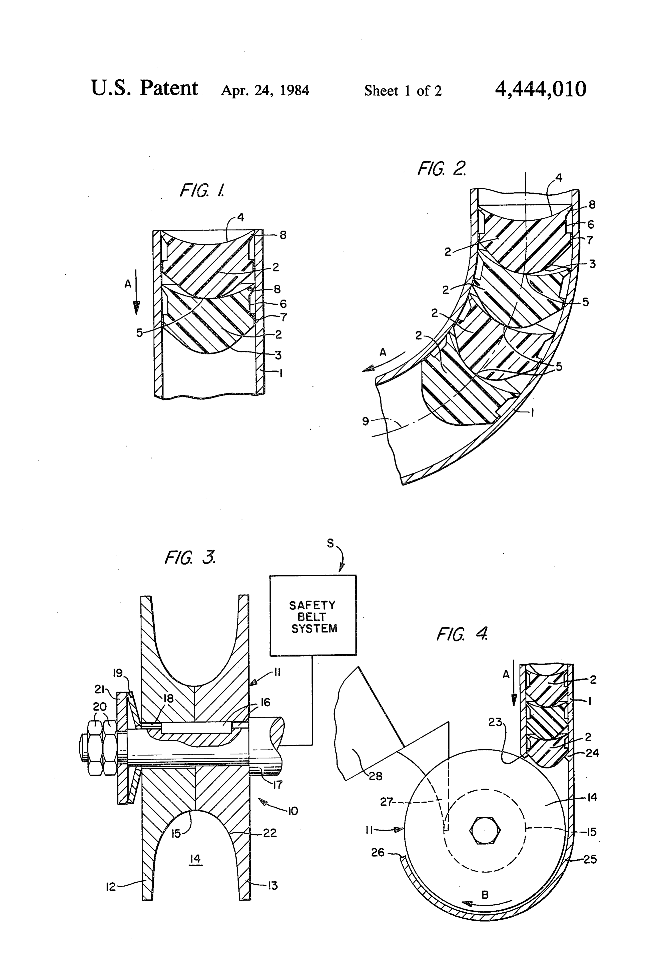
and thereby being deflected out of the profiled groove, As can be seen from FIG. 2, the acceleration mem so that additional acceleration members can then be bers 2 are also held in a defined fashion in curved pipe driven into the profiled groove which now is empty zones and/or move therethrough in an orderly manner, again. wherein the contact surface 5 is laterally displaced by Depending on the utilization and accommodation of an only minor extent with respect to the center, de the rotary power element of this invention, it can be picted by the pipe axis 9.
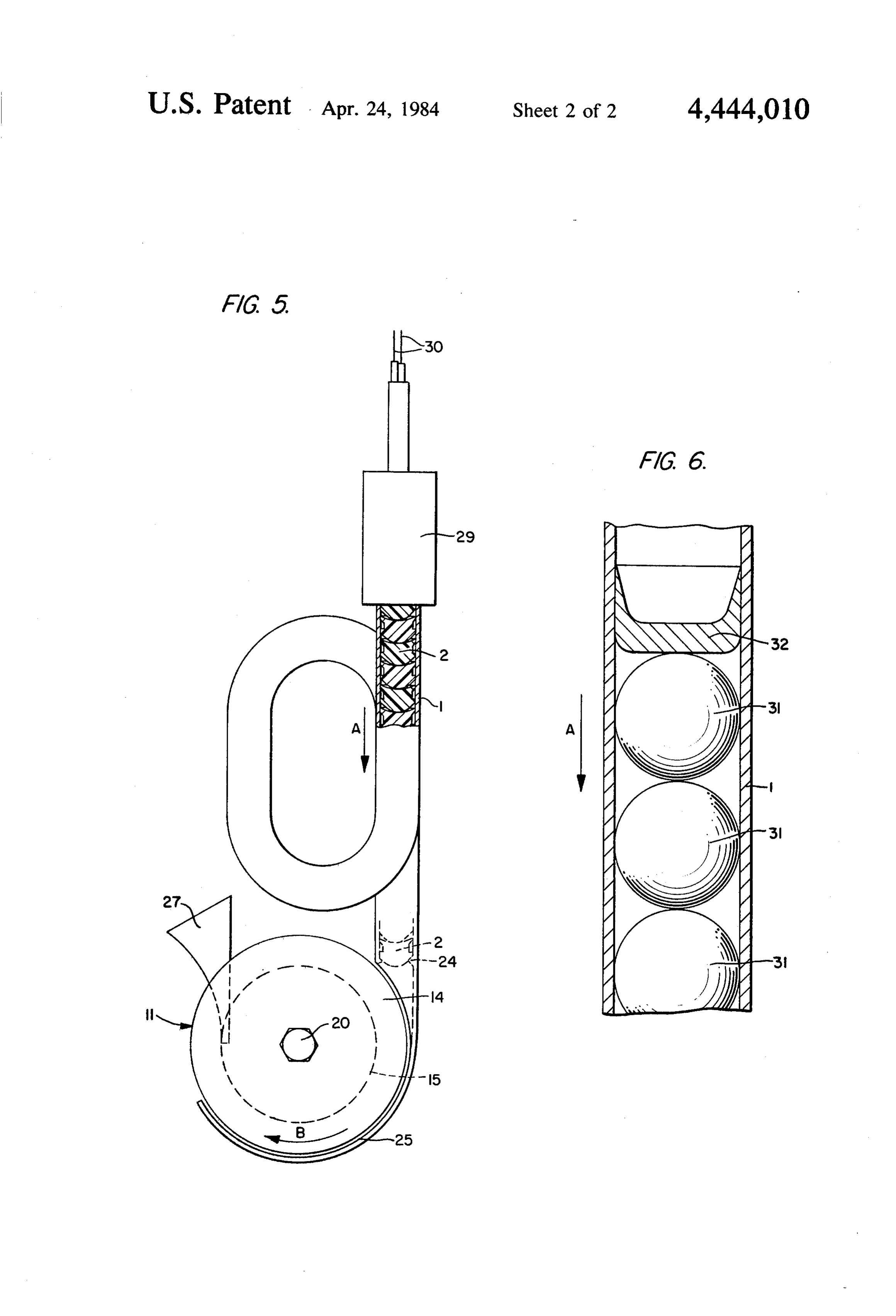
advantageous to collect the acceleration members, after The rotatable drive mechanism 10 shown in FIG. 3 these members have completed their function, i.e. after 10 on an enlarged scale and in cross section is fashioned as acceleration of the drive mechanism, in a collecting a wheel 11 composed of the two disk-shaped halves 12 device, such as a container, a bag, or the like. However, and 13, between which the peripherally extending pro such a collecting device can also be constituted, for filed groove 14 is formed with a cross section which example, by cavities in structural parts of automotive continuously narrows toward the bottom 15; the accel vehicles, airplanes, or the like. 15 eration members 2 can be injected into this groove with The rotary power element of this invention is uti a friction fit and optionally an additional shape-mating lized, in particular, in conjunction with automatic or contact under the effect of the compressed gas. The two also rigid safety belts in vehicles, airplanes, or the like; disks 12 and 13 are connected via the tongue-and however, it can also be applied in case of safety nets or groove joint 16 to the shaft 17 of the drive mechanism similar safety devices in conveyances which are to be 20 10 for rotation therewith; this shaft is, in turn, fixedly activated in an accident situation. In this connection, connectible, for example, to the belt reel of a vehicle the rotatable drive mechanism can also effect the simul safety belt system generally designated by the reference taneous deployment of several safety devices, for exam character 5. The "outer' disk 12 is mounted to be dis ple by arranging on both sides of the drive mechanism placeable with a small radial play 18 on the shaft 17, and respectively one belt roll-up means and connecting the 25 is urged with a definite spring force against the other mechanism therewith. Moreover, it is basically also disk 13 via the biased cup spring 19 and the pressure possible to utilize the element in all those cases wherein plate 21 held by means of the screw connection 20. The kinematic processes during which a rotational move groove 14 of the disk wheel 11 can optionally be rough ment occurs are to be executed in response to a signal. ened on its surface 22, for example. This can be, for example, the coiling of ropes, the ten 30 In FIG. 4, the disk wheel 11 is shown in a side view, sioning of coil springs, the starting procedure of recip and the pipe 1 with acceleration members 2, associated rocating engines, or also translatory motion processes with the wheel, is shown in a sectional view. At the exit initiated by way of a rotational movement with the end 23 of the pipe 1, the inwardly projecting mounting interposition of a rack or the like. 24 for the acceleration members 2 is provided to secure Embodiments of the invention are shown schemati 35 the members until the function is triggered, for example cally in the drawings and will be explained in greater against vibration or shock stresses in the conveyance. detail below with reference thereto, identical reference The mounting 24 can be, for example, several holding numerals being used for the same parts in the various lugs distributed around the pipe circumference, or also figures. In the drawings: an annular holding collar. A tight sealing of the pipe 1 FIG. 1 shows a fragmentary view of a straight tubu is unnecessary. The mounting 24 is pressed aside when lar element; the function is triggered by the acceleration members FIG. 2 shows a fragmentary view of a curved tubular moving in the direction of arrow A so that the accelera element; tion members are injected into the groove tangentially FIG. 3 shows a drive mechanism; to the base 15 of the groove, indicated in dashed lines. FIG. 4 shows a drive mechanism in an elevational 45 To prevent a premature exiting of the acceleration view with associated tubular element; members 2 from the groove 14 during operation of this FIG. 5 is an elevated view partly in section of a ro device and rotation of the disk wheel 11 according to tary power element of this invention; and arrow B, this groove is provided along part of its pe FIG. 6 shows another embodiment of the tubular riphery with the cover 25, here formed integrally with element illustrated in FIG. 1. 50 the pipe 1. The deflecting means 27, shown as a wedge The tubular element 1, shown in FIGS. 1 and 2 on an shaped baffle, is arranged at a predetermined distance enlarged scale and in a sectional view, is fashioned as a from the end 26 of the cover, this deflecting means pipe having a circular cross section wherein the sepa urging the acceleration members 2 from the groove 14 rate acceleration members 2 made of a thermoplastic and guiding them into the collecting or catching device synthetic resin with a given form are inserted in mutual 55 28, shown only partially in a fragmentary view. contact therein. The ejection or motion direction of the FIG. 5 shows a practically complete rotary power acceleration members 2 in the pipe 1 is indicated by the element with a pipe 1 bent into a loop shape and with arrow A. The acceleration members 2 exhibit at their acceleration members 2 arranged therein in mutual front ends the convex surface 3 and at their rear ends contact and having a predetermined configuration, with the concave surface 4, the curvature of the surface 4 a disk wheel 11, a cover 25, and baffle 27. At the "inlet being lesser than that of surface 3. The central contact side' end of the pipe 1, the pipe is connected, for exam area 5 of the acceleration members 2 with respect to one ple, by a threaded connection with the compressed-gas another is smaller than the inside pipe cross section. On generator 29 shown in elevational view, this generator their peripheral surfaces, the acceleration members 2 being preferably a propellant charge cartridge arranged exhibit the continuous recess 6 limited toward the front 65 in a cartridge chamber and adapted to be triggered via by the guide strip 7 and toward the rear by the lip 8 the two electrical ignition lines 30. When using this serving as the guiding and sealing element. The strip 7 rotary power element as a tensioning means for respec and the lip 8 are in contact with the pipe wall on the tively one safety belt, pipes having a free inside diame 8 ter of between about 8 and 20 mm with a length of about cartridge chamber and is adapted to be triggered via 200-400 mm and with a corresponding “column” of a electrical ignition means.
plurality of acceleration members proved to be advanta 11. A rotary power element according to claim 1, geous. The wall thickness of these pipes, manufactured wherein said rotatable drive mechanism includes a from steel as customarily used for pressure pipes, was wheel defining a continuous profiled groove along a between about 0.5 and 2 mm. circumferential surface and said acceleration members Finally, FIG. 6 shows on an enlarged scale a frag are driven into said rotatable drive mechanism and mentary view of a pipe 1 wherein the acceleration mem engage the profiled groove.
bers are constructed as balls 31 of preferably hard syn 12. A rotary power element according to claim 1, thetic resin. In this case, it is advantageous to arrange a O wherein means are provided for enabling a connection piston 32 of preferably a synthetic resin on the side of the rotatable drive mechanism to a safety belt system facing the compressed-gas generator, not shown. It is of a vehicle.
furthermore suitable to fashion the piston 32 in a dish 13. A rotary power element for actuating tensioning shape to attain a satisfactory seal and utilization of the devices which comprises a rotatable drive mechanism, a compressed gases. To avoid movements of the balls 31, 15 compressed-gas generator means, a tubular element for example, due to jarring during transportation, these between the drive mechanism and the compressed gas balls are, in turn, retained with an appropriate displace generator means, and a plurality of preformed accelera able or deformable holding means at the exit-side end of tion members arranged in the tubular element, said the pipe 1. compressed-gas generator means including a propellant What is claimed is: 20 charge means for simultaneously driving said pre 1. A rotary power element for actuating tensioning formed acceleration members forward through and out devices which comprises a rotatable drive mechanism, a of said tubular element against the drive mechanism compressed-gas generator means, a tubular element under the action of compressed gas to rotate and to between the drive mechanism and the compressed-gas accelerate the drive mechanism; said acceleration mem generator means, and a plurality of preformed accelera 25 bers being made of a synthetic resin and having annular tion members arranged in mutual contact with each guide elements at the forward and rearward ends of a other in said tubular element, said compressed-gas gen peripheral surface thereof, with the rearward guide erator means including a propellant charge means for element providing a sealing lip contacting the wall of simultaneously driving said acceleration members in the tubular element and the rotatable drive mechanism mutual contact forward through and out of said tubular 30 comprising a wheel with a continuous profiled groove element against the drive mechanism under the action along its circumferential surface that is associated with of compressed gas to rotate and to accelerate the drive the acceleration members to be accelerated, the shapes mechanism. and dimensions of the profiled groove and of the accel 2. A rotary power element according to claim 1, eration members, respectively, conforming to each wherein said acceleration members are in mutual 35 other whereby the acceleration members are driven contact on an area smaller than the cross-sectional area into the profiled groove under the effect of the com of said acceleration members. pressed gas to produce rotation and accleration of the 3. A rotary power element according to claim 2, wheel.
wherein at least one of the mutually contacting surface 14. A rotary power element according to claim 13 areas of two acceleration members is of a convex shape. 40 wherein the profiled groove has means to expand its 4. A rotary power element according to claim 3, cross section against a continuously effective force. wherein the contact surface area contacting the convex 15. A rotary power element according to claim 14, surface contact area of one acceleration member and wherein the wheel has two circular halves placed provided by the other acceleration member is fashioned against each other, between which the profiled groove as a concave surface of a lesser curvature. 45 is formed and which can be axially urged apart against 5. A rotary power element according to claim 4, a continuously effective force of a spring. wherein the acceleration members, positioned in the 16. A rotary power element according to claim 13, tubular element in the advancing direction, have an at wherein a cover is associated with the wheel, this cover least substantially convex front face and an at least sub partially extending over the profiled groove of this stantially concave rear face. 50 wheel.
6. A rotary power element according to one of claims 17. A rotary power element according to claim 16, 1-5, wherein each acceleration member is made of one wherein the wheel is associated with a deflecting means of a cylindrical, disc-shaped, and plug-like configura extending into the profiled groove for guiding the at tion and is provided on its peripheral surface with at least one acceleration member out of this groove. least one recess extending in the peripheral direction. 55 18. A rotary power element according to claim 17, 7. A rotary power element according to claim 6, characterized in that the drive mechanism is associated wherein the acceleration members have annular guide with a collecting means for receiving the plurality of elements in the zone of the forward and rearward ends acceleration members after the plurality of members of its peripheral surface. have carried out the function of effecting rotation of 8. A rotary power element according to claim 7, said rotatable drive mechanism.
wherein the rearward guide element is simultaneously 19. A rotary power element according to claim 17, fashioned as a sealing lip contacting the wall of the wherein said deflecting means includes a wedge-shaped tubular element. baffle member extending into the profiled groove and 9. A rotary power element according to claim 8, arranged at a predetermined distance from said cover wherein each acceleration member is made of a syn 65 for urging and guiding the acceleration members from thetic resin. the groove.
10. A rotary power element according to claim 1, 20. A rotary power element for actuating a tensioning wherein the propellant charge means is arranged in a device which comprises a rotatable drive mechanism, a 9 compressed-gas generator means, a tubular element gage the profiled groove defined by said wheel to cause between the drive mechanism and the compressed-gas rotation and acceleration of the drive mechanism. generator means, and a plurality of preformed accelera 21. A rotary power element according to claim 20, tion members arranged in the tubular element; said wherein each acceleration member has an annular guide rotatable drive mechanism including a wheel defining a continuous profiled groove along a circumferential element providing a sealing lip contacting the wall of surface; said compressed-gas generator means includes the tubular element.
a propellant charge means for simultaneously driving 22. A rotary power element according to claim 21, said acceleration members in mutual contact forward wherein each acceleration member is made of a syn through and out of said tubular member into said drive 10 thetic resin.
mechanism under the action of compressed gas to en : x x: k
Provenance
- Collection
- Patents citing this work
- Pages
- 9
- Method
- pdftotext (the PDF's own text layer) + pdftoppm 300dpi page scans
- Patent office record
- patents.google.com →
- Source
- Google Patents citing-documents table
- Assignee
- Dynamit Nobel Aktiengesellschaft
- Published
- 1984-04-24
- Transcribed from
- patentimages.storage.googleapis.com →