

patent · US4445570A
High pressure combustor having a catalytic air preheater
1 May 1984
Text
Page 1scan →
United States Patent (19)
Retallick
54) high pressure combustor having a
Catalytic air preheater
76 Inventor: William B. Retallick, 1432 Johnny's
Way, West Chester, Pa. 19380
52 U.S.C. ........................................ 166/59; 60/723;
58) Field of Search .................................... 166/57-59,
2,621,477 12/1952 Powter et al. .................... 60/746 X 2,707,029 4/1955 Hartesveldt ........................... 166/59 3,223,081 12/1965 Hunt ................. 166/58 X 3,804,163 4/1974 Bradley et al. ....................... 166/59 3,826,080 7/1974. De Corso et al. ... 60/39.55
4,019,316 4/1977 Pfefferle ............................ 60/723 X 4,047,877 9/1977 Flanagan ............................... 60/746 4,197,700 4/1980 Jahnig ....... . . 60/723 X 4,199,024 4/1980 Rose et al. ............................ 166/59 4,237,973 12/1980 Todd ..................................... 166/59
4,265,615 5/1981 Lohmann ............................ 431/353 4,377,205 3/1983 Retallick ............................... 166/59
Foreign patent documents
708017 4/1965 Canada .................................. 166/59 107027 1/1980 Canada .... ... 60/723 Primary Examiner-George A. Suchfield
Attorney, Agent, or Firm-William H. Eilberg
A combustor for generating a mixture of steam and combustion gas is located downhole in an oil well, so that the mixture can be injected directly into the reser voir, to displace heavy oil from the reservoir. The com bustion is built up in stages, with each stage supplying hot air to the following stage. The first stage comprises a catalytic heat exchanger, which preheats the incom ing air. One side of the exchanger is coated with cata lyst. On this side of the exchanger the preheated air burns a clean fuel, so that heat flows through the metal wall of the exchanger to preheat the incoming air. The heated air from the first stage is used to ignite and burn a heavy fuel such as crude oil, which is burned in the second stage and following stages.
6 Claims, 5 Drawing Figures
Drawings
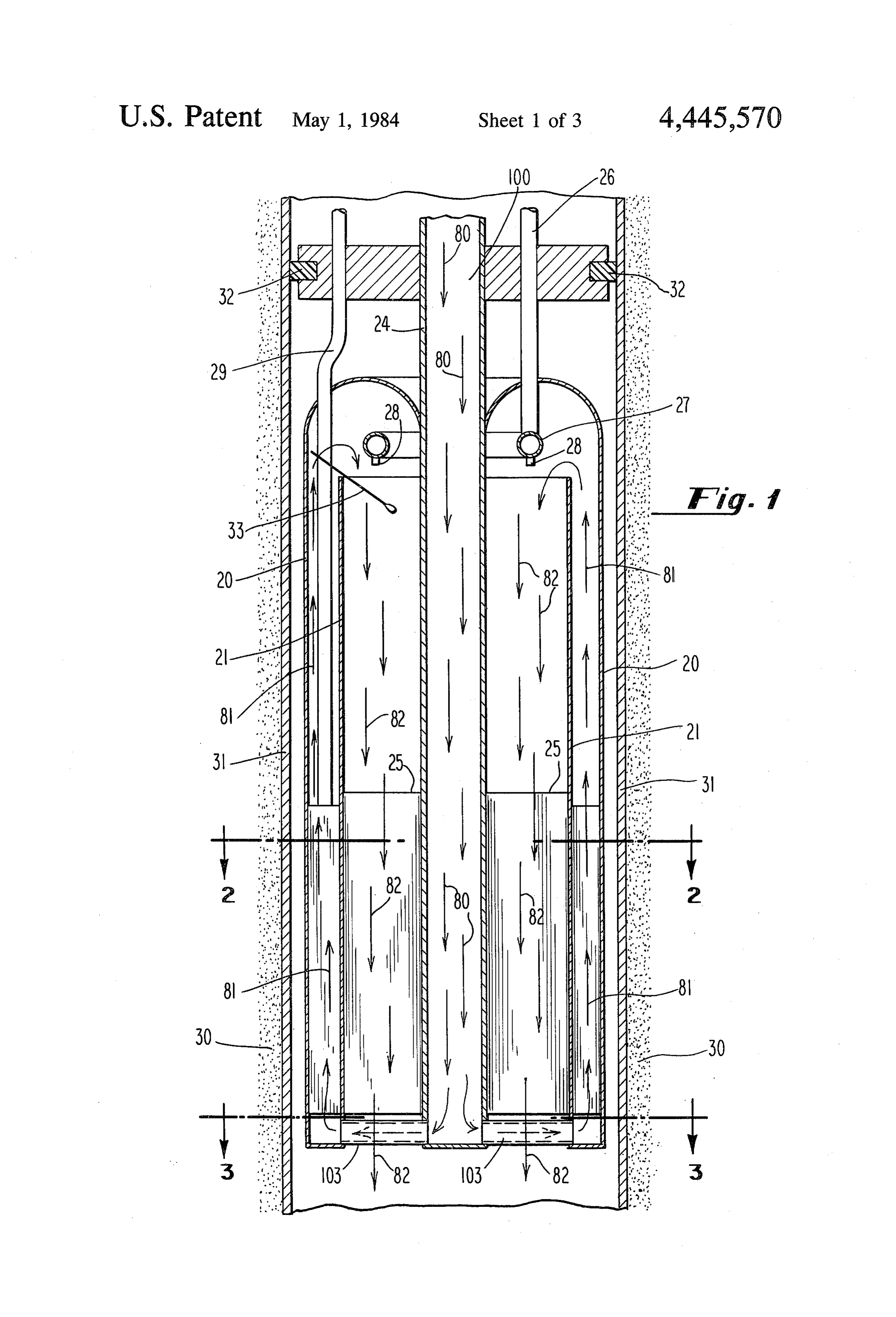
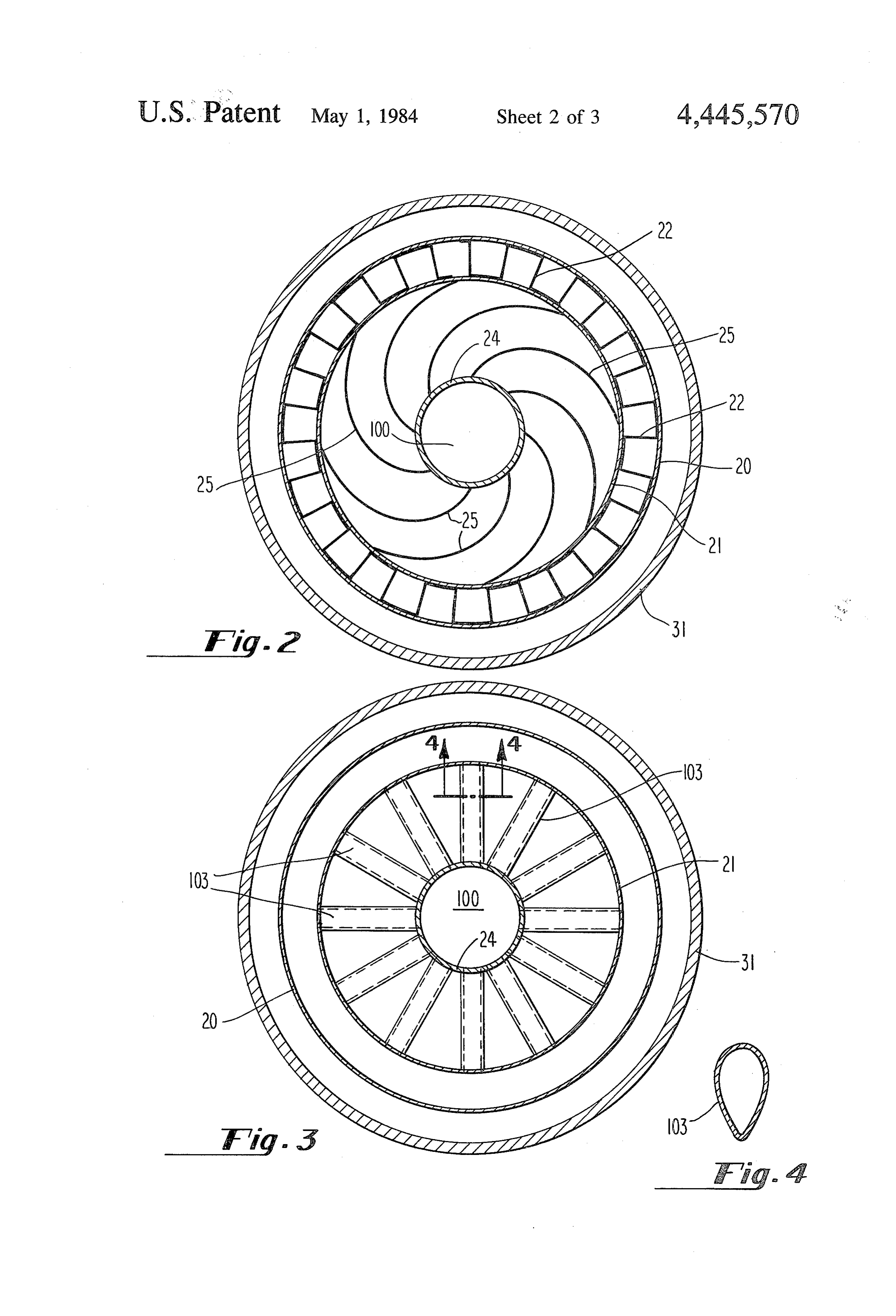
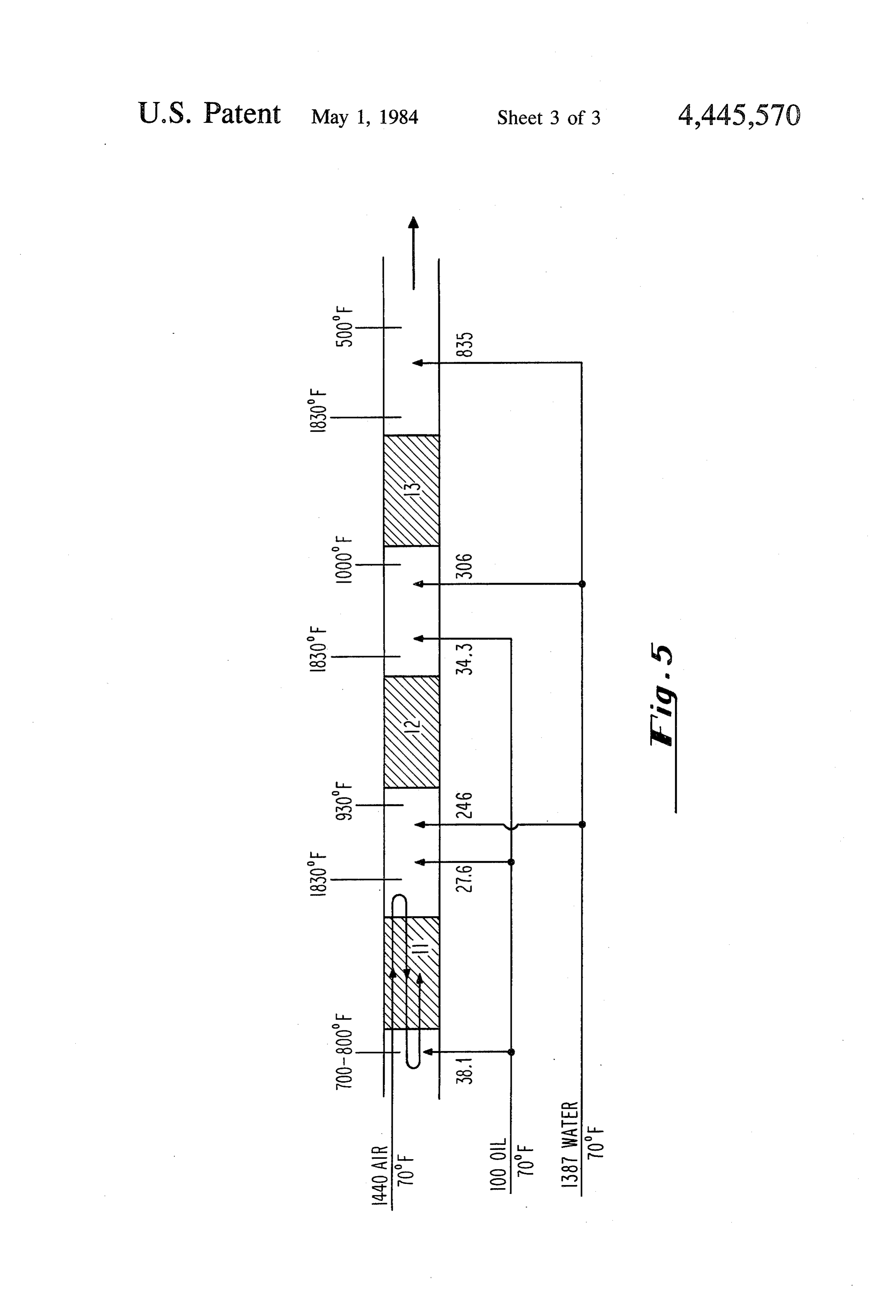
FIG. 2 is a cross-sectional view taken along the line
FIG. 1 is a vertical cross-section of the first stage of are 246 pounds of water fed between the first and sec the combustor, showing the flow path of air through the ond stages, 306 pounds between the second and third catalytic heat exchanger. stages, and 835 pounds after the third stage.
Page 2drawing sheetscan →
Page 3drawing sheetscan →
Page 4drawing sheetscan →
Page 5scan →
FIG. 2 is a cross-sectional view taken along the line
HIGH PRESSURE COMBUSTOR HAVING A 2-2 of FIG. 1.
CATALYTIC AIR PREHEATER FIG. 3 is a cross-sectional view taken along the lin
BACKGROUND OF THE INVENTION 5 FIG. 4 is a cross-sectional view taken along the line This invention relates to high pressure combustors 4-4 FIG.
of FIG. 3.
schematic flow diagram of one embodi for generating a mixture of steam and combustion gas ment of the invention, showing three stages of combus downhole in an oil well. The mixture is injected into the tion.
surrounding oil reservoir to displace heavy oil from the 10 reservoir. DETAILED DESCRIPTION OF THE The energy consumption in this process is great. It INVENTION takes the energy equivalent of one barrel of oil to dis FIG. 5 is a schematic diagram which illustrates the place three barrels of oil from the reservoir. There is an basic operation of the invention. The three stages of incentive to burn the cheapest fuel available, which is 15 combustion are designated by reference usually the heavy crude oil produced from the same and 13. The structure of first stage 11 numerals is described in reservoir. Heavy oils will not light off and burn without detail later in this section. Stages 12 and 13 may be substantial heat. It is simpler to heat air rather than oil, merely an open pipe, or may have more complex struc because the weight of air is 14-15 times the weight of tures. As indicated, air, oil and water each at 70 F., are oil. Also, heavy oil is not suitable for use in a catalytic 20 fed to the combustor. The designation of 70 F. is meant heat exchanger, which is part of the present invention, to indicate ambient temperature, and is not to be because heavy oil would foul the surface of the heat deemed critical. The numbers at the left-hand side of the exchanger. This invention discloses a means for provid figure (1440, 100 and 1387) indicate relative amounts by ing heated air for burning heavy oil in the later stages of weight. Thus, for 100 pounds of fuel oil, having a net a multi-stage combustor. 25 heating value of 18,500 BTUs per pound, one needs SUMMARY OF THE INVENTION 1440 pounds of air to burn all the oil to yield a combus tion gas that contains essentially no oxygen. The 1387
In this combustor the combustion is built up in stages, pounds of water is just enough to give a final mixture of with each stage supplying heated air to the following combustion gas and steam at 500 F. which is suitable stage. The first stage comprises a catalytic heat ex 30 for injecting into the oil reservoir. The relative amounts changer, for preheating incoming air. One side of the of fuel and air are calculated from heat and mass bal exchanger is coated with catalyst. On this side of the ances. It is understood, however, that the numbers exchanger the preheated air burns a clean fuel, such as shown in the figure are for illustrative purposes only, natural gas or distillate oil, so that heat flows through 35 and that the invention can be operated with other ratios, the metal wall of the exchanger and preheats the incom as will be explained below.
ing air. The heated air leaving the first stage is used to For this calculation, the fuel was assumed to be oil, ignite and burn a heavy fuel such as crude oil, which is and the same oil was fed to all three stages. The pre burned in the second stage and following stages. Thus, ferred fuel for stages 12 and 13 is crude oil or topped the relatively expensive "clean' fuel is used only in the crude. Crude oil should not be fed to stage 11 because it first (catalytic) stage, and the second and following would foul the catalyst. The fuel to stage 11 must be a stages can be fueled with cheaper heavy crude oil. clean distillate oil or a gas such as methane or natural It is an object of the invention to provide a combustor butgas. This substitution will change the flow rates slightly, for generating a mixture of steam and combustion gas not the temperatures.
downhole so that the mixture can be injected directly 45 In the embodiment shown in FIG. 5, air is supplied into the oil reservoir. only to the first combustion stage 11. As illustrated, the It is another object to provide a combustor wherein times, air is directed through this combustion stage three the combustion is built up in stages so that each stage shown.the air being forced to go back and forth, as It is on the third pass through stage 11 that provides heated air for the following stage. combustion occurs. The combustion stage 11 is so de It is another object to provide a stage combustor 50 signed wherein the first stage is a catalytic heat exchanger for which isthat the combustion therein pre-heats the air making a first or second pass through this stage preheating the incoming air. of the combustor. Structural details of the combustor It is another object to provide a stage combustor will be given below.
wherein heavy crude oil can be burned in the second FIG. 5 indicates the temperatures at the input and stage and following stages. 55 output ends of each stage of the combustor. These tem It is another object to provide a staged combustor wherein only the first stage requires relatively expen peratures under the are the temperatures that will be obtained operating conditions given in FIG. 5. How sive fuel. ever, other sets of temperatures are satisfactory, subject Other objects and advantages of the invention will be to the requirement that the temperature never become apparent to persons skilled in the art, from a reading of 60 so low as to quench the combustion. the following brief description of the drawings, the The numbers below each combustion stage in FIG. 5 detailed description of the invention, and the appended indicate the relative amounts of oil and water that are claims. fed to each stage. Thus, the 100 pounds of oil is divided BRIEF DESCRIPTION OF THE DRAWINGS 65 as 38.1 pounds to the first stage, 27.6 pounds to the second stage, and 34.3 pounds to the third stage. There
FIG. 1 is a vertical cross-section of the first stage of are 246 pounds of water fed between the first and sec the combustor, showing the flow path of air through the ond stages, 306 pounds between the second and third catalytic heat exchanger. stages, and 835 pounds after the third stage.
Page 6scan →
The temperature leaving each stage is shown as 1830 Spokes 103 are, in this embodiment, of a streamlined F., which is high enough to insure complete combus cross-section, as illustrated in FIG. 4, taken along the tion. The temperatures at the input ends of each stage line 4-4 of FIG. 3.
must be high enough to insure that the fuel will ignite 5 beThe fuel-air mixture in the first combustion stage can ignited by glow plug 33. Alternatively, the combus and burn. Also, the temperature entering successive stages should increase (note that FIG. 5 shows the input tion can be started by preceding the gaseous or oil fuel temperatures for stages 11, 12 and 13 to be 700-800F., with a hypergolic fuel that ignites spontaneously upon and 1000 F., an increase from one stage to the next). contact with air. Either way, the first combustion can This increase in temperature is to compensate for the 10 be a flame that anchors itself to the donut ring 27. The lower concentration of oxygen after each combustion flame is allowed to burn long enough to heat the cata lytic surface sufficiently for it to sustain catalytic com
FIG. 1 is a vertical section through the inlet to the bustion. Then the flow of fuel is momentarily cut off to preheating stage, which silows, in more detail, a possi extinguish the flame. Next the flow of fuel is resumed, though of course now there is no flame, and the com ble design for first stage 11. Air enters through duct 100, 15 bustion defined by duct wall 24, in the direction of arrow 80, heater inproceeds on the catalytic surface of the air pre first stage 11.
and returns through the annular space between walls 20 When the feed to the first stage has been set at 38.1 and 21, as indicated by arrows 81. The preheated air pounds of oil and 1440 pounds of air, as shown in FIG. then flows through the annular space between duct wall 24 and wall 21 as indicated by arrows 82. Fuel enters 20 5,1830 the temperature leaving the first stage will level out at through duct 26, donut ring 27, and nozzles 28, and wouldF.,reach and the temperature leaving the third stage 13 1830 F., even though combustion in the mixes with the preheated air. Reference numeral 25 last two stages has not yet started. The injection of designates the upper extremity of a set of involute fins, water after the third stage is started, to quench the final to be described below, and the space between nozzles temperature to 500' F.
28 and the upper extremity of fins 25 is for mixing the 25 ahead of second stage Next, oil and water are injected 12, gradually increasing to the fuel and the air. Duct 29 is one of several that carries rates shown in FIG. 1. Simultaneously, the amount of fuel or water to the successive combustion stages. water injected after third stage 13 is increased to hold The mixture of combustion gas and steam that the final temperature at 500 F. The third stage 13 is emerges from the combustor (along the path of arrows brought on stream in the same way. Now all of the 82) is forced into the sand formation 30 of the oil reser 30 temperatures and flow rates are as shown in FIG. 1. voir. The oil well casing 31 is cemented into the forma It is understood that one can "set' the feed to a given tion in a conventional manner, and a pressure seal be stage to be a specified amount of fuel, water etc., either tween the casing and the combustor is formed by pack by actually measuring the flow, or by an indirect means. ing 32. A practical indirect means is to monitor the temperature FIG. 2 is a section across the bore of the catalytic 35 at both the input and outputside of a combustion stage, heat exchanger in first stage 11. The exchanger has a and to vary the flow rates of fuel and water (or, in the double wall, 20 and 21, separated by a corrugated fin 22, case of the first stage, fuel and air) until the desired to increase the heat transfer to air flowing between temperatures are achieved. When the desired input and walls 20 and 21. The corrugated fin 22 oscillates be output temperatures are observed, one can infer that the tween the walls 20 and 21 of the annulus. There is flow rates are correct.
shown central duct wall 24. Air flows through duct 100 In FIG. 5, the final temperature of 500 F. is fixed by (as indicated by arrows 80 in FIG. 1) and returns the two ratios, air/oil and water/oil. All other tempera through the annular space between walls 20 and 21. tures can be varied without changing these ratios. To Curved fins 25 extend from wall 21 to duct wall 24. The 45 burnraise the temperature from the first stage, one would curve of the fins is the involute of a circle. Adjacent fins peraturesmore of the oil in the first stage. To raise the tem are equidistant over their entire arc, which is the reason inject from the second and third stages, one would for using the involute. Thus, the annulus between wall extra waterwater less after ahead of these stages, and inject the the third stage.
21 and duct wall 24 is filled with a uniform density of The temperature entering the second stage, in the surface for heat transfer and combustion. The inside of wall 21, the outside of duct wall 24, and all of the sur 0 embodiment shown in FIG. 5, is calculated by heat balance, from mixing 27.6 pounds of oil and 246 pounds face of fins 25 are coated with catalyst. The inside of of duct wall 24 is bare, i.e. devoid of catalyst. Heat gener tionwater, gas both at 70 F., with 1478 pounds of combus from the first stage. This calculated 930 F. is ated on the surface of a fin 25 is conducted along the arc the temperature that would exist if mixing were com of the fin to wall 21 or to duct wall 24. 55 pleted before any of the 27.6 pounds of oil were burned. . . Some of the channels formed by corrugated fin 22 It is the lowest temperature that can exist. The actual can serve as ducts for the fuel and the water going to the temperature will likely be higher because some burning successive stages of combustion. takes place simultaneously with mixing. The tempera FIG. 3, a cross-sectional view taken along the line ture must be kept high enough to insure that there is no 3-3 of FIG. 1, illustrates the structure of the first com 60 possibility of extinguishing the combustion. This is the bustion stage, near its output end. Well casing 31 is criterion which is most important in designing combus shown, as well as walls 20 and 21, together with duct tors having different numbers of stages. If the feeds to 100 defined by duct wall 24. The figure also illustrates a the second and third stages were combined and fed to a plurality of hollow spokes 103 which connect duct 100 single combined stage, the calculated minimum temper with the space between walls 20 and 21. As is also 65 ature entering that combined stage would be only about shown in FIG. 1, spokes 103 provide a path for air to 100 F. If burning did not proceed simultaneously with flow out of duct 100 and back through the space be mixing, the combustion would certainly be extin tween walls 20 and 21. .. . guished. But if the combined feeds to the second and 7 third stages were divided among more than two stages, As stated above, the number of stages of combustion the calculated minimum temperatures entering these can be varied, as long as operating conditions are stages would be higher than the temperatures in FIG. 5, chosen so as not to quench the combustion. Other de but the outlet temperatures would remain at 1830 F. sign details are variable, such as the number of passes There are some simple combustors that comprise made by the air through the first stage. These and other only the first stage in FIG. 5. For example, one can burn modifications are to be deemed within the spirit and 38.1 pounds of air with 1440 pounds of air, and quench scope of the following claims. What is claimed is:
the combustion gas with 457 pounds of water. The 1. A catalytic combustor for generating a mixture of resulting mixture is at 500' F., which is right for inject ing into the oil reservoir. The mixture contains about 10 steam and combustion gas downhole in an oil well, comprising:
12% oxygen, however. In the preferred embodiment, (a) a nest of three coaxial metal pipes that define inner the mixture for injection contains no oxygen, which is and outer annular passages, why the additional stages were included in FIG. 5. (b) the wall in the inner annulus being coated with In a second example, one can substitute 34.5 pounds 15 catalyst, of methane gas for the 38.1 pounds of oil. The tempera (c) means for directing incoming air first through the ture from the first stage remains at 1830 F., and the central pipe, then through the outer annulus in the other temperatures and flow rates are almost un opposite direction, and then through the inner an changed. This amount of methane constitutes 4.2 mol% nulus in the first direction, and in the methane-air mixture, which is below the flamma 20 (d) means for mixing fuel with the air after it has bility limit of 5.3%. (The flammability limit is that traversed the outer annulus and before it has tra mol% of methane, or other combustible gas, below versed the inner annulus. which a flame will not travel through the mixture.) 2. The combustor of claim 1, wherein the inner annu Thus, the air and methane could be mixed at ground lus contains a nest offins having the shape of the invo level and piped downhole through a single pipe. The 25 lute of a circle, the fins being attached to both walls of problem of mixing air and fuel ahead of the first stage is the annulus, the fins being coated with catalyst. eliminated. There is no lower limit to the concentration 3. The combustor of claim 2 wherein the outer annu of combustible that can be burned over a catalyst, and lus is traversed by a corrugated fin that oscillates be this is the essence of this example. tween the walls of the annulus. In a third example, one can burn a mixture that con 30 4. A catalytic combustor for generating a mixture of tains, say, 4.2% methane and 8.4% oxygen, the remain comprising: steam and combustion gas downhole in an oil well, der being noncombustible gases such as nitrogen or carbon dioxide. What is important is that the methane (a) a nest of three coaxial metal pipes that define inner content is below the flammability limit, and that the 35 and outer annular passages, oxygen content is just sufficient to burn the methane (b) the walls of the inner annulus being coated with completely, so there is no oxygen in the combustion gas. catalyst,
One analogous mixture would contain 2.0% propane (c) means for directing a mixture of gaseous fuel and and 10.0% oxygen. The gases are mixed at ground level oxidizing gas first through the central pipe, then and piped downhole through a single pipe. The problem through the outer annulus in the opposite direction, of mixing air and fuel downhole is eliminated com and then through the inner annulus in the first direction.
pletely. The oxygen free combustion gas is quenched 5. The combustor of claim 4 wherein the inner annu with water and injected into the oil reservoir. 'lus contains a nest of fins having the shape of the invo In FIG. 5, the oil and water are injected into stages 12 lute of a circle, the fins being attached to both walls of and 13 in separate streams. The oil and water can as well 45 the annulus, the fins being coated with catalyst. be combined into an emulsion and fed as a single stream. 6. The combustor of claim 5, wherein the outer annu Also in FIG. 5, all of the air is fed to the first stage. It is lus is traversed by a corrugated fin that oscillates be quite possible to bypass some of the air to the later tween the walls of the annulus.
stages of combustion. k sk
Provenance
- Collection
- Patents citing this work
- Pages
- 7
- Method
- pdftotext (the PDF's own text layer) + pdftoppm 300dpi page scans
- Patent office record
- patents.google.com →
- Source
- Google Patents citing-documents table
- Assignee
- Retallick William B
- Published
- 1984-05-01
- Transcribed from
- patentimages.storage.googleapis.com →