

patent · US4447118A
Optical information transfer system
8 May 1984
Text
Page 1bibliographic recordscan →
United States Patent (19)
Mulkey
OPTICAL INFORMATION TRANSFER
SYSTEM
Inventor: Owen R. Mulkey, Bellevue, Wash.
73 Assignee: The Boeing Company, Seattle, Wash.
5ll int. Cl’................................................ G02B5/14 (52) U.S. C. ................................. 350/96.16; 250/227;
2,770,712 11/1956 Dros...................................... 362/26 2,831,453 4/1958 Hardesty . ... 116/288 2,900,949 8/1959 Baker .................................. 116/288 3,221,593 12/1965 Ferris .................................. 356/241 3,240,113 3/1966 Stechemesser et al. . ... 350/293 3,596,178 7/1971 Sklyaruk et al....................... 324/96 3,609,960 10/1971 Huther .................................. 368/67 3,675,552 7/1972 Papke. 354/219 3,800,058 3/1974 Bartok et al. 84/18 3,802,767 4/1974 Rambauske ...... ... 350/294 4,025,172 5/1977 Freiberg .............................. 350/294
4,027,945 6/1977 Iverson ............................. 350/96.22 4,078,548 3/1978 Kapany . ... 126/438 4,173,390 1 1/1979 Kiich ............. ... 350/96.16 4,190,318 2/1980 Upton, Jr. ........................ 350/96.20
4,346,961 8/1982 Porter ............................... 350/96.16 4,379,613 4/1983 Coburn ............................. 350/96.10
FOREIGN PATENT DOCUMENTS
53-89750 8/1978 Japan ................................ 350/96.16 Primary Examiner-John D. Lee
Attorney, Agent, or Firm-David G. Pursel
A system for transferring information via light signals from at least one station to at least one other station when the stations are generally capable of movement, one with respect to the other. In general, each station is capable of receiving and transmitting light signals through a light-conductor of light transparent material. At least one conical indentation is formed in the light conductor for the purpose of intercepting a portion of the light signals transmitted from one of the stations and reflecting the intercepted light signals to one of the other stations.
22 Claims, 10 Drawing Figures
Drawings
Page 2drawing sheetscan →
Page 3drawing sheetscan →
Page 4drawing sheetscan →
Page 5scan →
OPTICAL INFORMATION TRANSFER SYSTEM causes an image to rotate at twice the rate that the prism is rotated. By rotating the prism at half the speed of the
Background of the invention
rotating object, its image will appear to be stationary after passing through the prism.
The present invention relates generally to a system In addition to the derotating prism suggestion con for optically transferring information via luminous en tained in the aforesaid Iverson Patent, Iverson discloses ergy among two or more stations. More particularly, other variations for transferring light signals from a this invention pertains to a system for transferring infor rotating body to a non-rotating body by using multiple mation via light signals from at least one station to an channels, waveguides, concentric annular mirrors and other station when one of the stations is generally capa 10 optical slip rings. The optical slip ring embodiment ble of movement with respect to the other. contains bundles of optical fibers which are placed end As is appreciated by those skilled in the art, it is often to end coaxially with the axis of rotation. Light intro desirable to transfer information or control signals by light energy rather than by electrical energy, especially duced it into one bundle travels to the opposite end where couples across a small gap into the second bundle.
when the constraints of the operating environment pre Multichannel bundles are used by forming channels at clude using conventional electrical information transfer the coupled ends systems. For example, in some environments it is neces opaque material. into concentric circles separated by an sary to transfer information or control signals between There has been a wealth of work expended in the area two electrical circuits when one of the electrical cir of illuminating panels and instrument dial plates by cuits is operating with respect to a ground reference 20 injecting light into one or more of the surfaces of the level which is different from that of the other electrical panel or dial plate. For example, in Dros, U.S. Pat. No. circuit. Optical information transfer systems are partic 2,770,712, a dial ularly suitable for this application because they have the rays axially onto plate a rod is illuminated by projecting light having a cone shaped indentation inherent property of electrically isolating the reference in the end of the rod that voltage level of one electrical circuit from that of the 25 that the incident light raysisare attached to the dial plate so projected into the plate in other. The light weight of optical information transfer radial directions. See also, Hardesty, U.S. Pat. No. systems and their immunity to electrical interference are further properties which make these systems especially 2,831,453 which discloses an illuminated panel wherein useful in weapon systems and aircraft control systems light which travels in a plane parallel to the panel is where high reliability and survivability are critical. 30 intensified at desired locations in the panel by reflecting Optical information transfer systems are also ideal for from angular surfaces located below the areas desired to use in explosive and inflammable environments in order be highlighted. Baker, U.S. Pat. No. 2,900,949, discloses to avoid the hazards associated with conventional elec an arrangement for illuminating instrument dials by trical circuits. providing the dial with elliptical corners and placing a One of the more perplexing problems faced by de 35 light bulb at the focal point of each ellipse such that signers, manufacturers, and users of light information light from the bulb is evenly reflected from the corners transfer systems, has, for a number of years, been, and of the instrument dial to all areas in the plane. The light continues today to be, the need to transmit information rays concentrated at the center of the panel are re and control signals between one station that is moving flected from a truncated conical surface to a pointer with respect to a second station, or between two or located on either side of the panel. Huther, U.S. Pat. more stations moving at different speeds relative to No. 3,609,960, discloses a time piece dial wherein cones each other. In this connection, many efforts have been are placed below the hour marks so that light emitted made, and are continuing to be made, to solve this prob from a bulb embedded in the time piece dial is reflected lem. Initially, information was transferred by electrical from the cones and highlights the hour marks. signals and such efforts were primarily directed 45 The concept of using lenses, mirrors and reflective towards providing various forms of electrical slip rings surfaces to collimate or modify the direction of light for making electrical connections between a stationary energy is described in the art, for example, by Steche source of electrical signals and a rotating receptor of the messer et al, U.S. Pat. No. 3,240,113, which discloses an electrical signals. Typically, metal rings were mounted arrangement of mirrors and lenses which are used to on the rotating portion of the apparatus and the station 50 project panoramic photography at a horizontal angle of ary brushes that were connected to the source of electri view of up to 360'. Other representative patents show cal signals wore against the metal rings and conducted ing mirror and lens configurations include, for example: current into or out of the rotating member. This system Freiberg, U.S. Pat. No. 4,025,172 and Rambauske, U.S. was inherently susceptible to electrical and mechanical Pat. No. 3,802,767.
noise originating from the poor connection between the 55 Other representative patents of miscellaneous interest brushes and slip rings. The system was also limited in its include, for example, Bartok et al, U.S. Pat. No. frequency response due to the variations in the charac 3,800,058, which discloses an electro-optical organ em teristic impedence of the slip rings. ploying a rotating disk having numerous concentric With respect to transferring information optically, tracks of varying opacity and a light source for divert other efforts directed towards solving this problem ing light through all of the tracks to establish a time have included use of a derotating pris in which is ar varying light beam representative of musical tones. The ranged to rotate at one-half the speed of relative rota concept of using opposed reflecting surfaces which tion between the rotating and stationary portions of an transmit incident light by multiple reflections for the apparatus. A typical example of this approach is sug purpose of increasing the efficiency of a solar panel is gested in Iverson, U.S. Pat. No. 4,027,945, in FIG. 4. 65 disclosed in Kapany, U.S. Pat. No. 4,078,548. A meter The derotating prism shown therein is a direct vision for measuring electrical quantities which uses a bi-con prism which will invert an image in one position, but cave lens at the center of a moving part is disclosed by when turned 90' will reinvert the image. This property Sklyaruket al, U.S. Pat. No. 3,596,178. A camera hav 6 ing an apparatus in the region of its view finder for vides a groundless information transfer system that does indicating the adjustment of the camera is disclosed by not depend upon maintaining a consistent signal refer Papke, U.S. Pat. No. 3,675,552. The apparatus is formed in a frustoconical configuration having a large end ence level level between two points. A system requiring low signal transmission is usually very difficult to oper forming a light receiving surface and a small end form ate in a high ing a light discharging surface with the small end being varies because noise environment because the ground annularly shaped with an indentation defining the inner environment; a probleminduced of noise that is in the ground from the avoided by using the edge of a light discharging surface. The surface of the system of this invention.
indentation can be coated in order to improve the effi ciency of the device. In the Ferris Patent, U.S. Pat. No. 10 BRIEF DESCRIPTION OF THE DRAWINGS 3,221,593, a cone is used to permit visual inspection of The foregoing features and many of the attendant the inside of boiler tubes or other industrial piping.
Consequently, insofar as is presently known, while appreciated of advantages this invention will become more readily the prior art is replete with numerous proposed pro by reference to theinvention as the becomes better understood following detailed description when cesses for illuminating dial plates and proposed tech 15 taken in conjunction with the accompanying drawings, niques using complex fiber optic cables and or mirrors and lenses requiring relatively large space and being wherein:
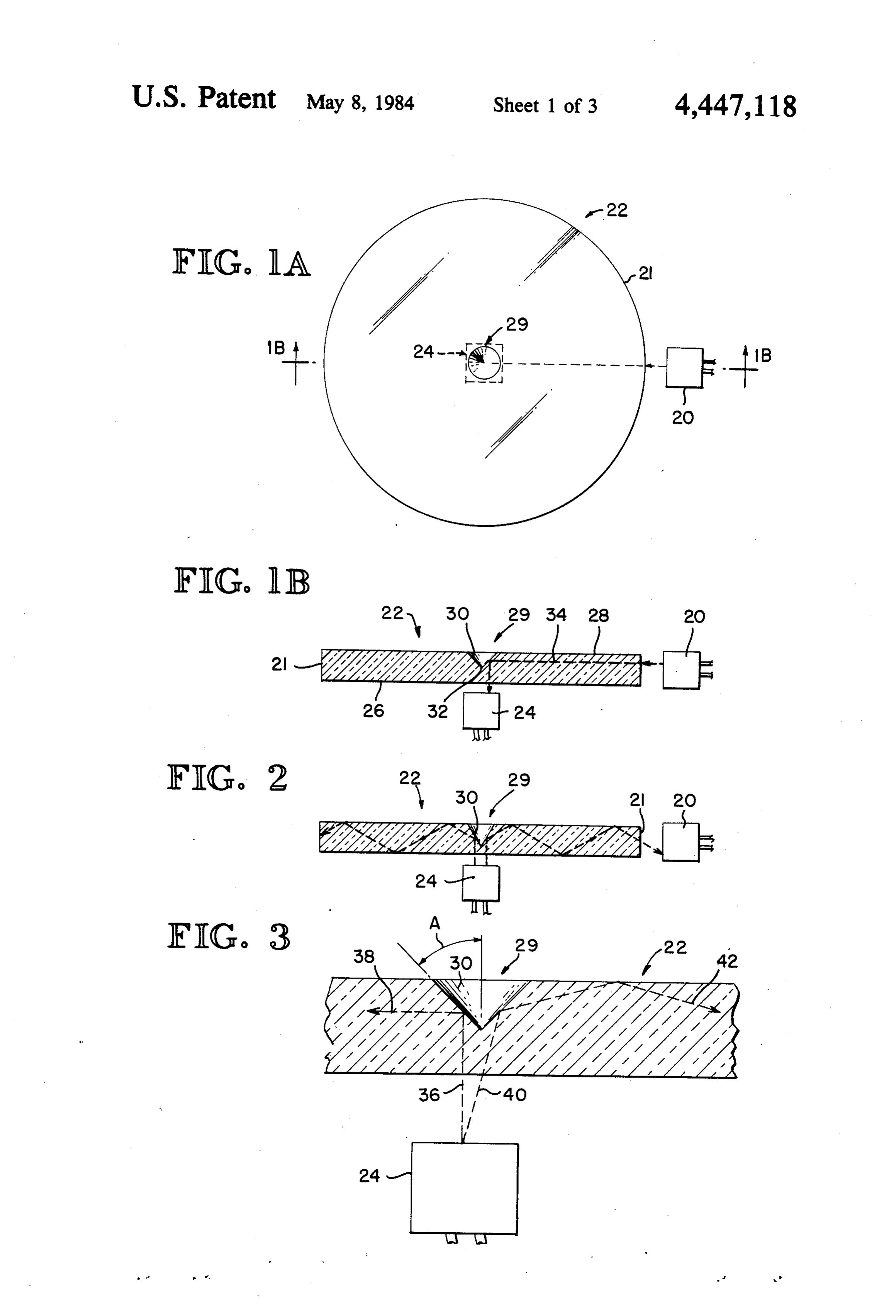
therefore limiting in application for transmitting light FIG. 1A is a plan view of an optical information transfer system embodying the features of the present signals, prior to the advent of the present invention invention.
there has been no known effective and reliable method 20 or apparatus that is simple in construction and capable FIG. 1B is a section taken along line 1B-1B in FIG. of permitting information to be transferred by light 1A.
signals from a first station to another station that is 1AFIG. 2 is a sectional taken along line 1B-1B in FIG. and is similar to FIG. 1B, but here illustrates the moving with respect to the first station.
25 transfer of information in a direction opposite to that
SUMMARY OF THE INVENTION shown in FIG. 1B.
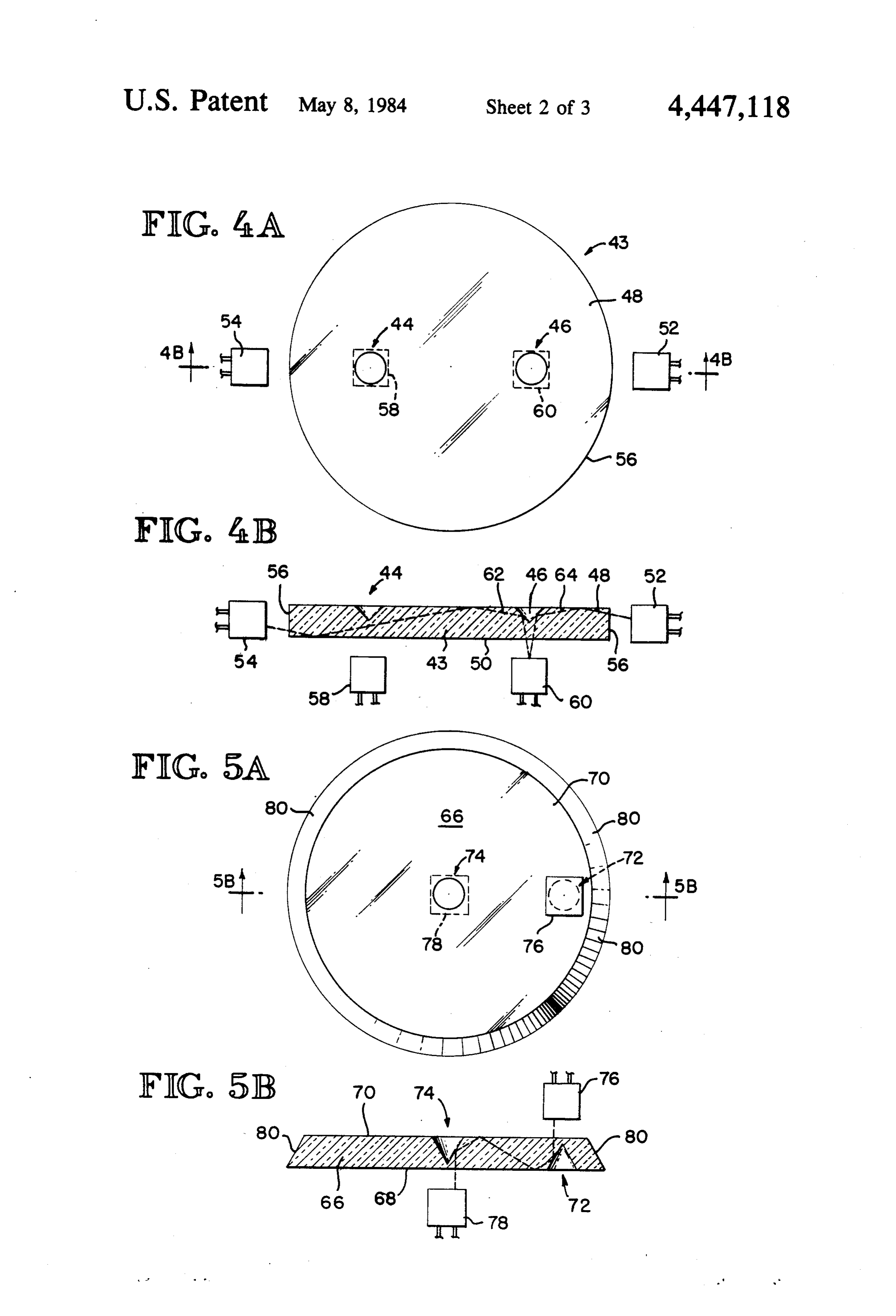
Accordingly, it is a general aim of the present inven FIG. 3 is a detailed illustration of the use of a source tion to provide a system for transferring information via of collimated and noncollimated luminous energy. light signals from at least one station to at least one FIG. 4A is a plan view of an optical information other station when the stations are generally capable of 30 transfer system embodying features of the present in movement, one with respect to the other. The optical vention.
information transfer system of this invention has a first FIG. FIG. 4B is a sectional taken along line 4B-4B in set of one or more stations for transmitting light signals 4A.
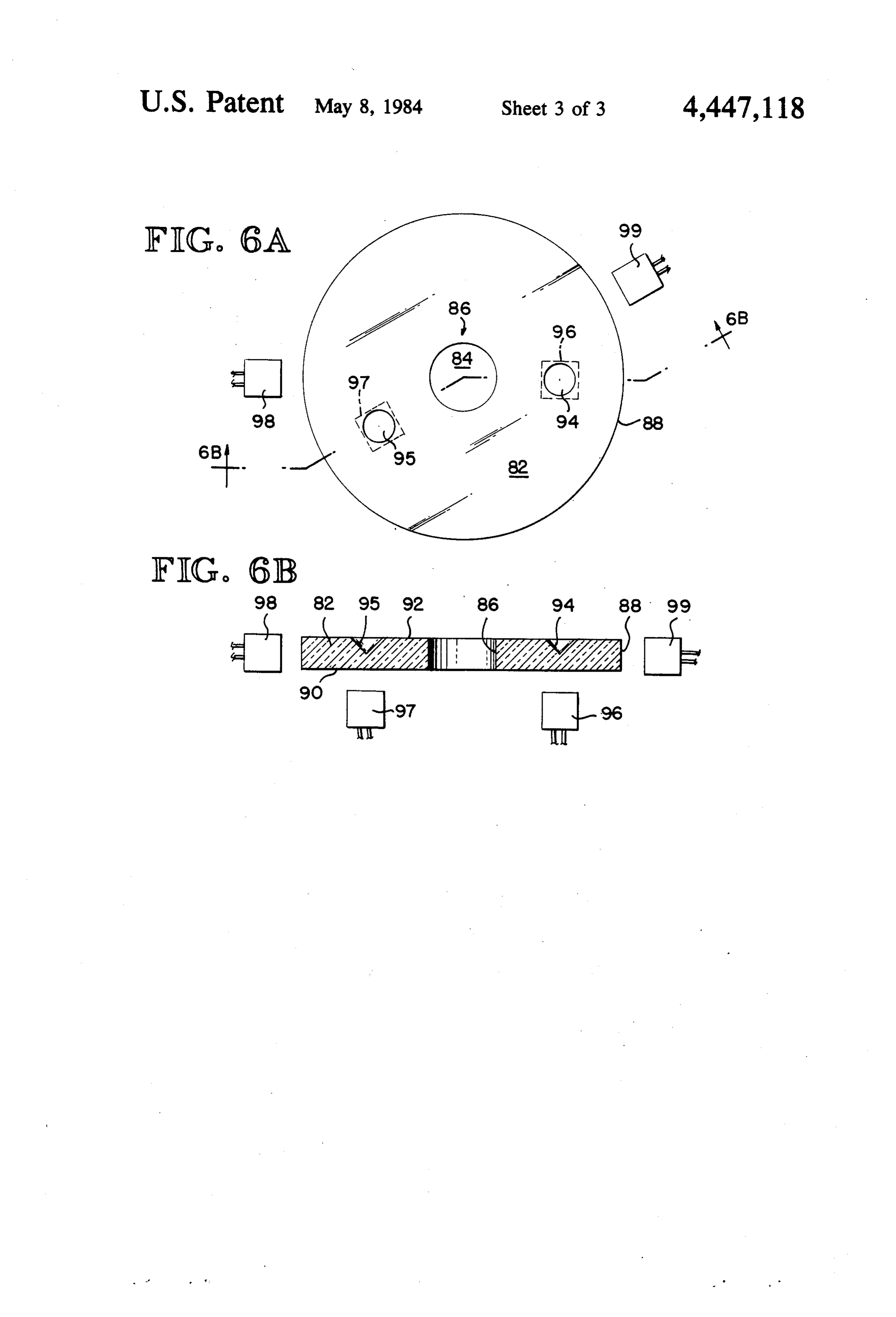
and a second set of one or more stations operable for FIG. 5A is a plan view of an optical information receiving light signals and a light transparent member 35 transfer system with the light transparent member hav through which the light signals propagate. The light ing a beveled peripheral edge.
transparent member has at least one conical indentation FIG. 5B is a sectional taken along line 5B-5B in formed therein for the purpose of intercepting light rays FIG. 5A propagating from the first set of stations and reflecting FIG. 6A is a plan view of an optical information the intercepted portion to the second set of stations. transfer system with the light transparent member hav In one of its important aspects, the invention provides ing a centralized cylindrical aperture therethrough. for two-way communication between the stations by FIG. 6B is a sectional along line 6B-6B in FIG. 6A. including, means for receiving light signals in the first DETAILED DESCRIPTION OF THE set of stations as well as for means for transmitting light PREFERRED EMBODIMENTS signals. Similarly, the second set of stations is provided 45 with means for transmitting light signals as well as Turning now to FIGS. 1A and 1B, a preferred em means for receiving light signals. bodiment of the present invention for transferring light One set of the stations is generally positioned adja signals, for example, between one station and another cent to the outer peripheral edge of the light transparent station has been diagrammatically illustrated. As shown member and is generally susceptible of relative motion 50 here, a first station 20 is positioned adjacent to an edge between the set of stations and the light transparent surface 21 which forms the peripheral boundary of disk member. The other set of stations is generally posi shaped light-conductor 22. Although light conductor tioned adjacent to one or both of the major surfaces of 22 is illustrated as having a "disk' shape, it will be the light transparent member with each station being readily appreciated by one skilled in the art that light located opposite the apex of a conical indentation 55 conductor 22 may assume any of many geometric formed in the surface of the light transparent member. shapes depending upon its application. A second station The optical information transfer system of this inven 24 is positioned adjacent a first major surface 26 of the tion is lightweight and inexpensive to produce. The disc. A second major surface 28 of the disc has a cone 29 construction and operating costs for this system are formed substantially in the center of the disc defining an minimal because the system has few elements and its operation is particularly uncomplicated. Typical appli indentation bounded by light reflecting conical surface 30. The central axis of the conical surface substan cations for this simple and reliable invention include tially normal to second major surface 28 of the disc and transmitting the data between the moving portions of its apex 32 is opposite second major surface 26. turrets, periscopes and radomes that are revolving.
A further particularly advantageous application is in 65 ple,Asashown in FIG. 1B, the first station 20 is, for exam source of light signals 34 that are optically cou a very noisy environment such as in an environment pled into disc 22. A portion of the light signals 34 propa where high power generators are operating. In such an gate through the transparent interior of the disc and are environment, the system of the present invention pro reflected from conical surface 30 and out of the disc to 7 the second station 24 which, for example, serves as a and be guided internally between the major surfaces of receptor of the light signals. the disk until it is intercepted by a conical surface or the In the embodiment described in FIGS. 1A and 1B, disk's edge surface. Typical materials used to fabricate the first station 20 is generally movable in a circular disc 22 include Lucite, plexiglass and ordinary glass. path about an axis that is normal to the first major sur The terms "light' and "luminous' energy as used face 26 of the disc and passing substantially through the herein are intended to have a broad connotation and center thereof. Second station 24 is in a generally fixed include radiant energy transmitted by wave motion spatial relationship with respect to disc 22-viz., disc 22 with wavelengths from about 0.3 microns to 30 mi and second station 24 are capable of conjoint rotational crons; this includes visible wavelengths (0.38 microns to movement about an axis normal to the disc and passing 10 0.78 microns) and those wavelengths, such as ultravio substantially through the center thereof. Thus, in accor let and infrared, which can be handled by optical tech dance with one of the important aspects of the present niques used for the visible region. It is not necessary invention, there has been provided a system for trans within the meaning of the above definition that the ferring light signals from one station to another and, radiant energy used in the subject invention be visible especially, from one station to another that is generally 15 light. The inventive priniciples will apply regardless of movable with respect to the first station. the frequency of the radiant energy and it is intended An alternative arrangement permits relative move that the light signals comprise any radiant energy for ment among the three elements; first station 20, disc 22 which a suitable source and detector exist. and second station 24. In this embodiment, the first Turning now to FIG. 2, a system essentially similar to station and the second station are movable, one with 20 that depicted in FIG. 1 is shown. However, second respect to the other, and the disc is also rotatable about station 24 now contains a source of luminous energy a central axis that is normal to its major surfaces. and first station 20 now contains a detector of luminous Although the light transmission system depicted in energy. Luminous energy emitted from second station FIGS. 1A and 1B shows a light transparent disc as the 24 is injected into transparent disc 22 where it is re element for transferring light signals from one station to 25 flected from conical surface 30. The reflected energy another, it will be appreciated by those skilled in the art propagates by internal reflection through the transpar that the element for transferring the light signals could ent disc and exits through edge surface 21 to be received assume any of a variety of shapes depending upon the by a detector positioned inside first station 20. In this particular application. Typically the light transparent manner, light signals may be transferred from second element, for example disc 22, will be relatively thin with 30 station 24 to first station 20. respect to the width of its major surface, viz., one-quar FIG. 3 is a more detailed illustration of the method of ter of an inch to one-eighth of an inch thick. The thick propagation of luminous energy emitted from second ness of the disc should be slightly less than the cross station 24. If second station 24 contained a source of sectional area of the active area of a source or detector collimated luminous energy then the collimated lumi positioned at station 20 in order to achieve maximum 35 nous energy is represented by the single ray 36 which efficiency in coupling luminous energy between the enters disc 22 and is reflected from conical surface 30. disk and the source or detector in station 20. Angle A represents the angle between a normal to the In the embodiment depicted in FIGS. 1A and 1B, first major surfaces of the disc and conical surface 30. Ide station 20 contains a source of luminous energy. Second ally, angle A would be 45 when a source of collimated station 24 contains a detector such as, for example, a luminous energy is used so that the reflected ray 38 is PIN (positive, intrinsic in type silicon) diode or an APD guided parallel to the major surfaces of the disc, causing (avalanche photo detector) device, which produces an minimal attenuation of the light energy from internal electrical output in response to the presence of luminous reflections.
energy incident on the device. The thickness of the disc Since this invention is also intended for use with is somewhat limiting upon the frequency response of 45 sources of noncollimated luminous energy, which is the this system so that one skilled in the art would want to typical case, the coupling efficiency of the system consider the tradeoff between the thickness of the disc would be increased by increasing angle A so that more and the cross-sectional active area of a particular source luminous energy from second station 24 would be cap or detector when determining the final design of a par tured and directed internally between the first and sec ticular system. It is also important to note that the cou 50 ond major surfaces of the disc towards first station. 20. pling efficiency between first station 20 and second In the instance when second station 24 contains a source station 24 is dependent upon several factors. The cou of noncollimated luminous energy, representated by ray pling efficiency is maximized by placing the stations as 40, the energy is internally reflected from conical sur closely as possible to disc 22 and by keeping disc 22 as face 30 and propagates by internal multiple reflections, thin as possible (commensurate with the cross-sectional 55 as represented by reflected ray 42, until it emerges from active area of the source or detector of luminous energy the edge of the disc.
as described, supra). The efficiency is further optimized In order to achieve maximum energy coupling it is by keeping the diameter of the disc as small as possible desirable to minimize the amount of luminous energy in order to reduce the total amount of radiating area. emitted from second station 24 that passes directly Again referring to FIGS. 1A and 1B, isc 22 is fabri through transparent disc 22 without being internally cated from any material that is transparfnt to luminous reflected and directed towards first station 20. energy and has a refractive index that is greater than One method of increasing the amount of luminous that of the surrounding environment in order to provide energy that is captured internally between the major maximum internal reflection of the light signals within surfaces of the transparent disk involves coating conical the disc. That is to say, if the refractive index of the 65 surface 30 as well as first major surface 26 and second light-conducting disk is greater than that of the sur major surface 28 with a reflective material. However, a rounding medium, luminous energy that is coupled into small portion of the disk's surface adjacent to station 24 the disk will propagate by multiple internal reflections is not coated so that luminous energy can be coupled 8 into and out of the disk. A further benefit derived from for transferring information by way of light signals from using a reflective coating is that the coating serves to a first station to a second one when the second station is insulate the major surfaces of the disc from contami generally moveable with respect to the first. As here nants having a higher refractive index than the transpar shown, light-conductor 66 is made from material that is ent material of the disc. If such contaminants were to substantially optically transparent and has a first major come in contact with the surface of the disc, then the surface 68 and a second major surface 70. A first conical contaminant would tend to conduct luminous energy indentation 72 is formed in first major surface 68 and a out of the disc, thus reducing the coupling efficiency of second conical indentation 74 is formed in second major the system. Excellent results have been achieved using surface 70. The apex of first conical indentation 72 is a thin coating of aluminum as the reflective material. 10 opposite second major surface 70 and the apex of sec However, other well known reflective materials may be ond conical indentation 74 is opposite first major sur used such, for example, as chromium, silver, gold, face 68. A first station 76 is positioned adjacent to the nickel or multiple layer dielectric films. second major surface and opposite the apex of first In keeping with the invention, FIGS. 4A and 4B conical indentation 72. A second station 78 is positioned depict a further embodiment wherein transparent disc 15 adjacent to the first major surface and is opposite the 43 has a first conical indentation 44 and a second conical apex of second conical indentation 74. Although light indentation 46 formed therein. First and second conical conductor 66 is illustrated as having the geometrical indentations are formed in second major surface 48 with shape of a disc, it will be appreciated by those skilled in their respective apexes opposite first major surface 50. the art that various other geometrical shapes may be A first plurality of stations comprising station 52 and 20 used where the application so requires. station 54 is positioned adjacent to the disc's edge sur Still referring to FIGS. 5A and 5B, light-conductor face 56. A second plurality of stations comprising sta 66 has a beveled edge 80 forming its peripheral bound tion 58 and station 60 is positioned adjacent to first ary. The peripheral boundary is beveled so that lumi major surface 50 with each station in the second plural nous energy which is coupled into light-conductor 66 ity being positioned opposite the apex of a correspond 25 and propagates to the peripheral boundary will be re ing conical indentation. It is, of course, an important flected from the beveled edge back into the interior feature of this invention that relative motion is permit portion of the light-conductor. Thus, the optical cou ted between one or more of the stations in the first pling efficiency of this system is increased since less plurality and the light transparent member. luminous energy is propagated out of the disc through Still referring to FIGS. 4A and 4B, information is 30 the peripheral boundary, permitting the reflected por transferred optically from one plurality of stations to tion to have a higher probability of being intercepted by the other plurality. In the first instance, ray 62 repre the surface of one of the conical indentations and re sents the path that a ray of light may take when station flected to a light sensitive receptor. The optical cou 60 contains a source of luminous energy. Luminous pling efficiency may be further increased by applying a energy is injected into disc 43 and a portion of the lumi 35 reflective coating to the beveled edge so that a greater nous energy is intercepted by the reflective conical portion of the luminous energy which propagates to the surface of conical indentation 46. The intercepted por beveled edge is reflected from the mirrored surface tion is internally reflected between the parallel surfaces back into the light-conductor. of the disc and propagates to station 54, a member of the Still referring to FIGS.5A and 5B, either first station other plurality of stations. Conversely, one or more of 40 76 or second station 78 is provided with a means for the stations in the first plurality may contain a source of receiving and detecting luminous energy transmitted luminous energy and one or more of the stations in the from the other station. Furthermore, one skilled in the second plurality may contain a receptor which is sensi art would readily appreciate that both stations may be tive to luminous energy that is incident upon it. Under provided with the ability to receive and transmit infor these conditions, luminous energy emitted from one or 45 mation via optical signals. Although second conical more of the stations in the first plurality, for example indentation 74 is shown substantially at the center of station 52, will propagate along some path by means of light conductor 66, it will be readily appreciated by one internal reflections through the interior, light-transpar skilled in the art that the relative distances among first ent portion of the disc, as represented by ray 64. A conical indentation 72, second conical indentation 74 portion of the energy is intercepted by a conical inden 50 and beveled edge 80 may be varied in accordance with tation, for example conical indentation 46, and is di the requirements of any particular application. In par rected to the receptor in one of the stations in the sec ticular, second conical indentation 74 may be located ond plurality. anywhere on second major surface 70 and is not limited Those skilled in the art will, of course, readily appre to being located substantially at the center of light con ciate that any one or more of the stations may contain a 55 ductor 66 as shown in FIG. 5. source of luminous energy as well as a receptor that is Referring now to FIGS. 6A and 6B, a further aspect sensitive to luminous energy. In some instances it may of the present invention is illustrated. In accordance be desirable to employ a gallium-arsenide device, which with the present invention, light conductor 82 is pro exhibits the properties of a source of luminous energy as vided with an opening 84 substantially through its cen well as the properties of a receptor. When the device is ter. Opening 84 is defined by, surface 86. Although forward biased it acts as a light emitting diode and opening 84 is illustrated in FIG. 6 as a centralized cylin produces luminous energy. When the device is reversed drical aperture, those skilled in the art will appreciate biased it acts as a photodiode and is electrically sensitive that other geometrical openings can be employed in lieu to luminous energy which is incident upon its active thereof. For example, an annular opening may be best surface. 65 suited for passing cables or a shaft transversely through Referring now to FIGS. 5A and 5B, there is illus light conductor 82. However, in some applications it trated, and will herein below be described, a typical may be more desirable for opening 84 to assume a rect apparatus embodying features of the present invention angular or triangular configuration.
Page 9scan →
Light conductor 82 is bounded by edge surface 88, apex; one station including means for providing light first major surface 90 and second major surface 92. In its signals and the other station including means for receiv most general embodiment, light conductor 82 is shown ing light signals, whereby light signals from said one as having two conical indentations formed in second station are optically coupled into said light-conductor major surface 92. Conical indentation 84 is formed with and a portion of such light signals is intercepted by said its apex opposite first major surface 90, as is conical conical surface and is reflected to said other station. indentation 95. Station 96 is positioned adjacent to first 2. The system of claim 1 wherein said one station major surface 90 and opposite conical indentation 94. further includes means for receiving light signals and Station 97 is positioned adjacent to first major surface said other station includes means for providing light 90 and opposite conical indentation 95. Station 98 is 10 signals.
positioned adjacent to edge surface 88. Station 99 is 3. The system of claim 1 or 2 wherein said light-con positioned adjacent edge surface 88. ductor has the geometric shape of a disk. In carrying out one aspect of the present invention, 4. The system of claim 3 wherein said light-conductor light conductor 82 is capable of rotational movement has said indentation means spaced substantially at the about a central axis normal to first major surface 90 and 15 passing substantially through the center of the light center of said disk with respect to said edge surface. 5. The system of claim 4 wherein said first station is conductor. As described infra, stations 96, 97,98 and 99 rotatable circumferentially about an axis normal to said are capable of transmitting and receiving luminous en disk and passing through the center thereof. ergy. Light signals emanating from station 98, for in 6. The system of claim 1 or 2 wherein said light-con stance, propagate through optically transparent light 20 ductor has a centralized cylindrical aperture there conductor 82 until a portion of the light signals is inter through normal to said second major surface. cepted by the conical surface of one of the conical in 7. The system of claim 6 wherein said first station is dentations, such as conical indentation 94, and is re rotatable circumferentially about an axis normal to said flected to station 96, where the light signals are re disk and passing through the center thereof. ceived. 25 8. A system for transferring information via light Similarly, information may be conveyed from station signals, comprising: a light-conductor of light transpar 96, for example, to station 98. Light signals emanating ent material having an edge surface forming a periph from station 96 reflect from the conical surface of coni eral boundary thereof, a first major surface and a second cal indentation 94 and propagate through light conduc major surface substantially parallel to said first major tor 82 with a portion of the light signals passing through 30 surface, said second major surface having multiple in edge surface 88 and being received by station 98. In dentation means formed therein, each indentation general, the present invention permits relative move means being defined by a light reflecting conical surface ment between stations 98 and 99 and the combination of with its central axis normal to said second major surface light conductor 82 and stations 96 and 97. and its apex opposite said first major surface; a first This invention embodies the concept of minimum 35 plurality of stations positioned adjacent to said edge cost. The construction and operating costs for this sys surface; a second plurality of stations positioned adja tem are minimized because the optical information cent to said first major surface and each station in said transfer system of the present invention has few ele second plurality being positioned opposite the apex of a ments and the system's operation is not complicated. corresponding indentation means; one plurality of sta Stated simply, there are very few points where this tions including means for providing light signals and the system can fail and this reduces the cost in production other plurality of stations including means for receiving for quality assurance, and the training of repair person light signals, whereby light signals from said one plural nel. ity of stations are optically coupled into said light-con The optical information transfer system of the present ductor and a portion of such light signals is intercepted invention operates safely and effectively in most envi 45 by at least one conical surface and is reflected to at least ronments. The system of the present invention achieves one of said other plurality of stations. all of its stated objects and offers all of its stated advan 9. The system of claim 8 wherein each station in said tages by a design free from unnecessary and costly one plurality of stations further includes means for re subsystems. The optical information transfer system of ceiving light signals and wherein each station in said this invention is not limited to operation in hazardous 50 other plurality of stations includes means for providing environments nor is it limited solely to applications light signals.
involving high technology. This invention has an appli 10. The system of claim 8 or 9 wherein said light-con cation wherever information must be transferred reli ductor has the geometric shape of a disk. ably via light signals and the system must perform 11. The system of claim 10 wherein said first plurality safely, effectively, and economically. 55 of stations is rotatable circumferentially about an axis What is claimed is: normal to said first major surface of said disk and pass 1. A system for transferring information via light ing through the center thereof.
signals, comprising: a light-conductor of light transpar 12. The system of claim 8 or 9 wherein said light-con ent material having an edge surface forming a periph ductor has a centralized cylindrical aperture there eral boundary thereof, a first major surface and a second through normal to said second major surface. major surface substantially parallel to said first major 13. The system of claim 12 wherein said first plurality surface, said second major surface having a means of stations is rotatable circumferentially about an axis formed therein defining an indentation bounded by a normal to said first major surface of said light-conduc light reflecting conical surface with its central axis nor tor and passing through the center thereof. mal to said second major surface and its apex opposite 65 14. A system for transferring information via light said first major surface; a first station positioned adja signals, comprising: a light-conductor of light transpar cent to said edge surface; a second station positioned ent material having an edge surface forming a periph adjacent to said first major surface and opposite said eral boundary thereof, a first major surface and a second 10 major surface substantially parallel to said first major surface, said first major surface having a first means tion18.isThe system of claim 17 wherein said second sta in a fixed relationship with respect to said disk, formed therein defining an indentation bounded by a and said second station and said disk in combination are light reflecting conical surface with its central axis nor rotatable about an axis normal to said first major surface mal to said first major surface and its apex opposite said of said disk and passing through the center thereof. second major surface, and said second major surface 19. The system of claim 14 or 15 wherein said light having a second means therein defining an indentation conductor has a centralized cylindrical aperture there bounded by a light reflecting conical surface with its through normal to said second major surface. central axis normal to said second major surface and its 20. The system of claim 14 or 15 wherein said edge apex opposite said first major surface; a first station O surface of said light-conductor is beveled. positioned adjacent to said second major surface and 21. Light-conductor means for transferring informa opposite said apex of said first indentation means; a tion via light signals from one station adapted to pro second station positioned adjacent to said first major vide light signals to another station adapted to receive surface and opposite said apex of said second indenta light signals, said light-conductor comprising: a light tion means; one station including means for providing 15 transparent plate having an edge surface forming a light signals and the other station including means for peripheral boundary thereof, a first major surface and a receiving light signals, whereby light signals from said second major surface substantially parallel to said first one station are optically coupled into said light-conduc major surface, said second major surface having a tor and a portion of such light signals is reflected from means formed therein defining an indentation bounded said conical surface of one indentation means to said 20 by a light reflecting conical surface with its central axis conical surface of said other indentation means and is normal to said second major surface and its apex oppo received by said other station. site said first major surface, whereby light signals pro 15. The system of claim 14 wherein said one station vided by one station can be optically coupled into said further includes means for receiving light signals and light-conductor means and a portion of such light sig said other station includes means for providing light 25 nals are intercepted by said conical surface and are signals. reflected to said other station. 16. The system of claim 14 or 15 wherein said light 22. The light-conductor means of claim 21 wherein conductor has the geometric shape of a disk. said conical surface is covered with a coating which 17. The system of claim 16 wherein said first indenta inhibits said light signals from entering or leaving tion means and said first station are spaced substantially 30 through said coating.
at the center of said disk. it is
Provenance
- Collection
- Patents citing this work
- Pages
- 10
- Method
- pdftotext (the PDF's own text layer) + pdftoppm 300dpi page scans
- Patent office record
- patents.google.com →
- Source
- Google Patents citing-documents table
- Assignee
- The Boeing Company
- Published
- 1984-05-08
- Transcribed from
- patentimages.storage.googleapis.com →