

patent · US4449514A
Solar concentrator protective system
22 May 1984
Text
Page 1bibliographic recordscan →
United States Patent (19)
Selcuk
54). SOLAR
SYSTEM
CONCENTRATOR PROTECTIVE
(75) Inventor: M. Kudret Selcuk, La Canada, Calif. Assignee: The United States of America as represented by the Administrator of the National Aeronautics and Space
Administration, Washington, D.C.
Int. Cl.................................................. F24J 3/02 52 U.S. C. .................................... 126/418; 126/438;
1,951,403 3/1934 Goddard ....... ... 126/440 X 4,158,356 6/1979 Wininger ............................. 126/438
4,373,512 2/1983 Hirt ..................................... 126/4 Primary Examiner-Larry Jones:
ava
Attorney, Agent, or Firm-Paul F. McCaul; Thomas H. Jones; John R. Manning
A system is described for use with a solar concentrator such as a parabolic dish type that concentrates solar radiation onto a small opening (18) of a receiver, for protecting the receiver in certain circumstances, includ ing tracking failure wherein the concentrated solar radiation would fall on the face plate (26) surrounding the receiver opening and burn it, or in the event of lack of coolant circulation which could cause burning of the receiver cavity walls (22). The protective system in cludes a shutter mechanism (30) stored in an open con figuration beside the receiver opening and operable in case of failure to close shutters (34) over the opening, while also moving the mechanism away from the open ing and closer to the dish concentrator so that only less concentrated solar radiation must be blocked by the shutter mechanism. The shutter mechanism can include
a fuse wire (52) having one portion surrounding the receiver opening and another portion which supports the shutter mechanism against moving towards its closed position. A tracking failure causes concentrated sunlight to strike the fuse wire to break it and allow the shutter mechanism to move towards a closed position. 8 Claims, 10 Drawing Figures
Drawings
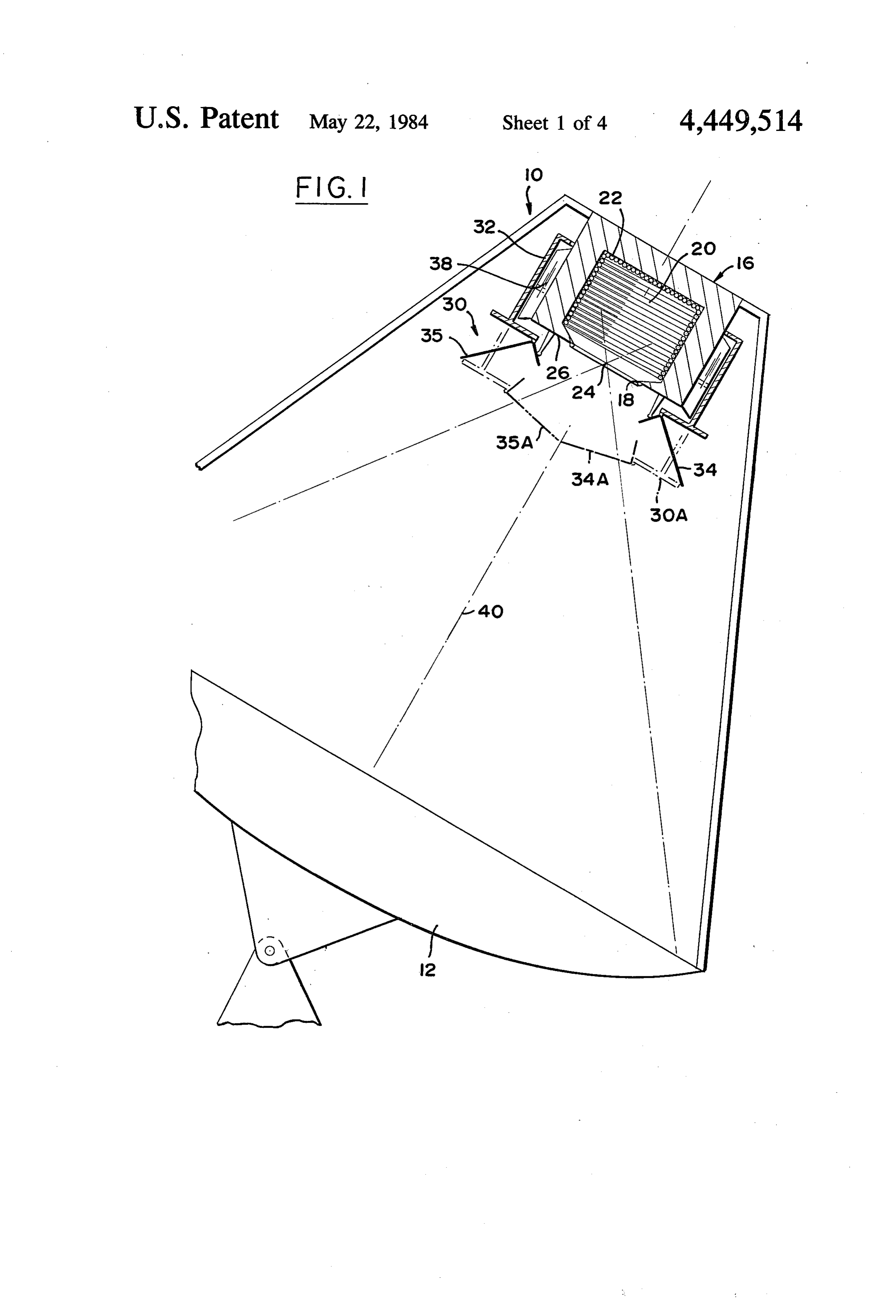
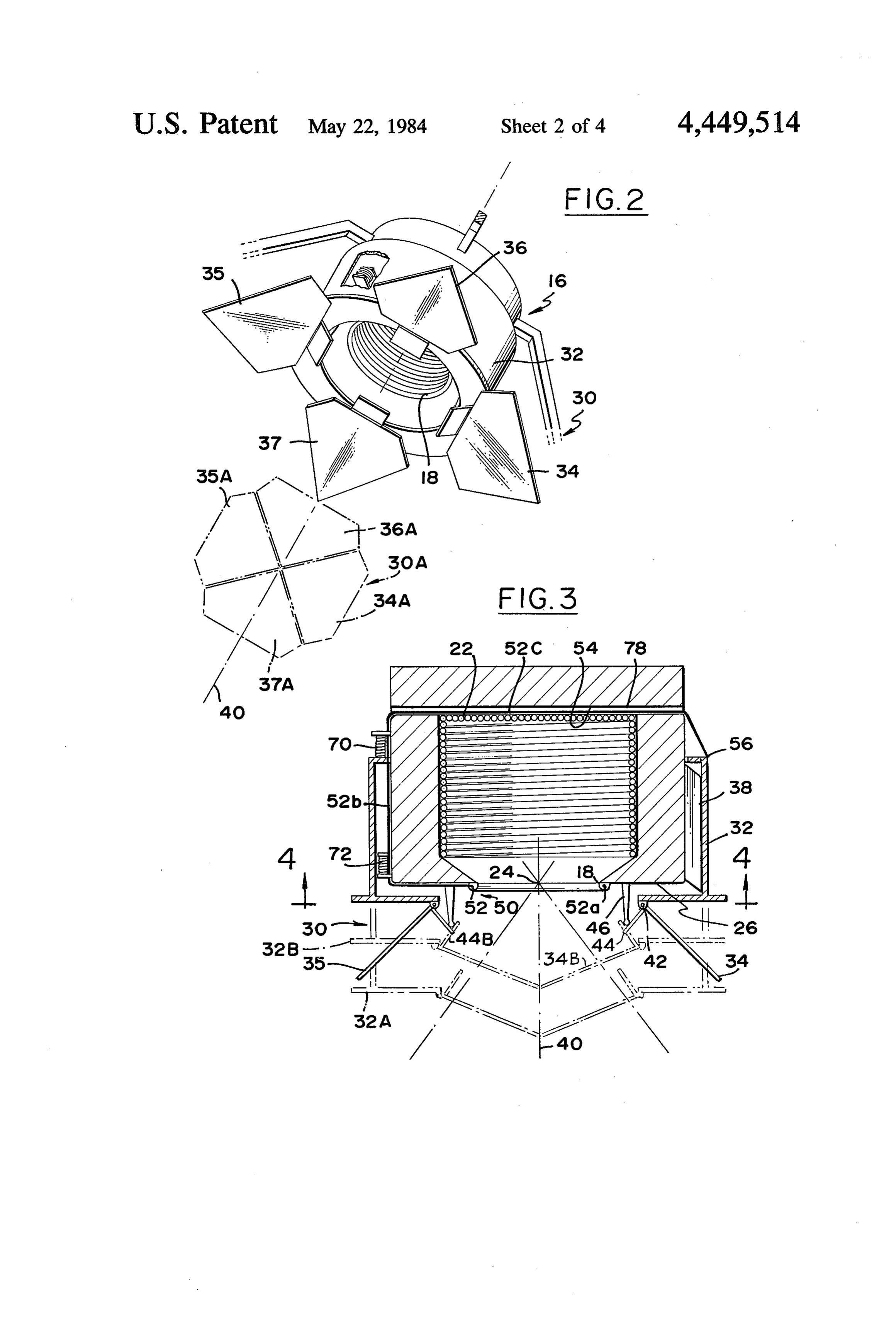
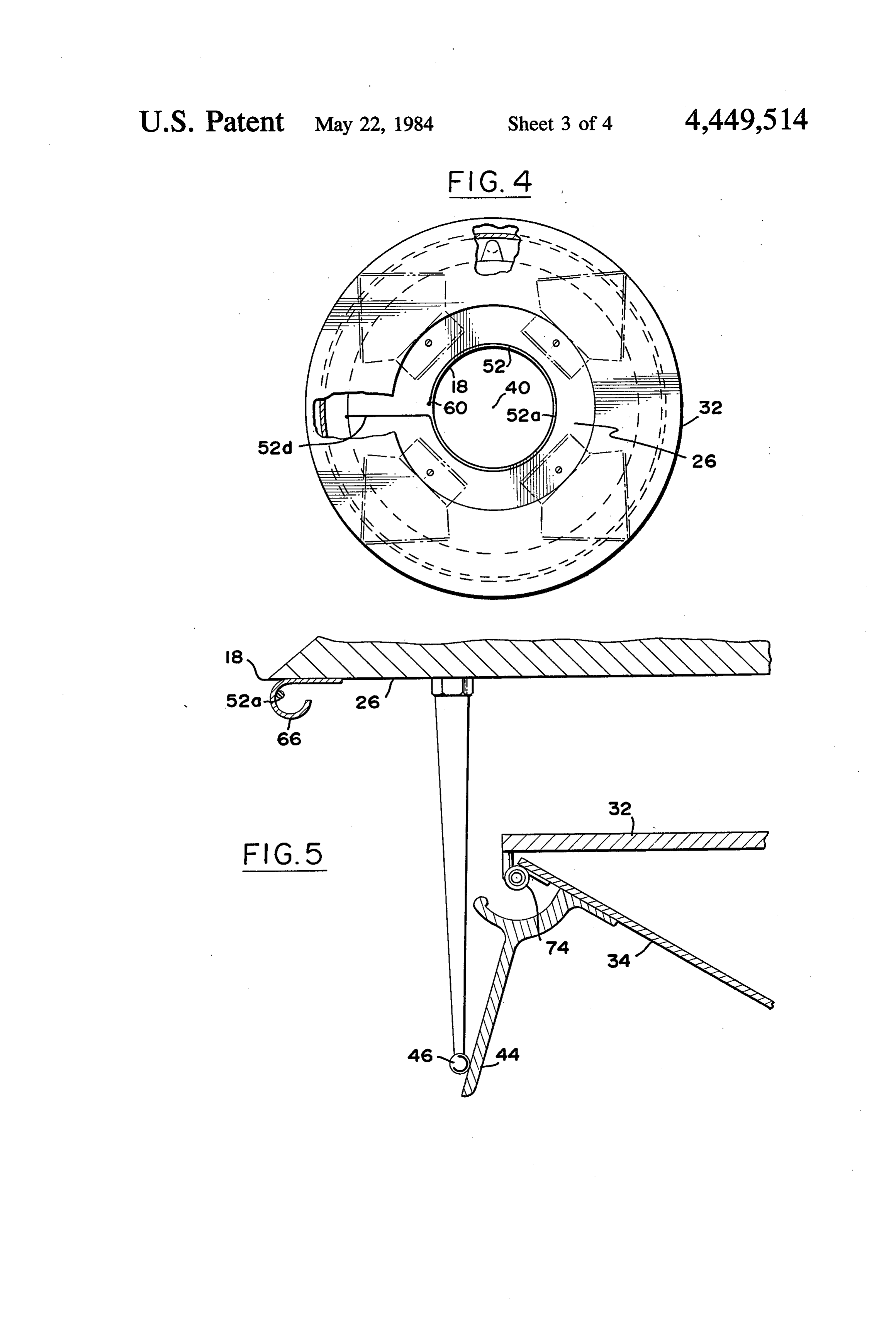
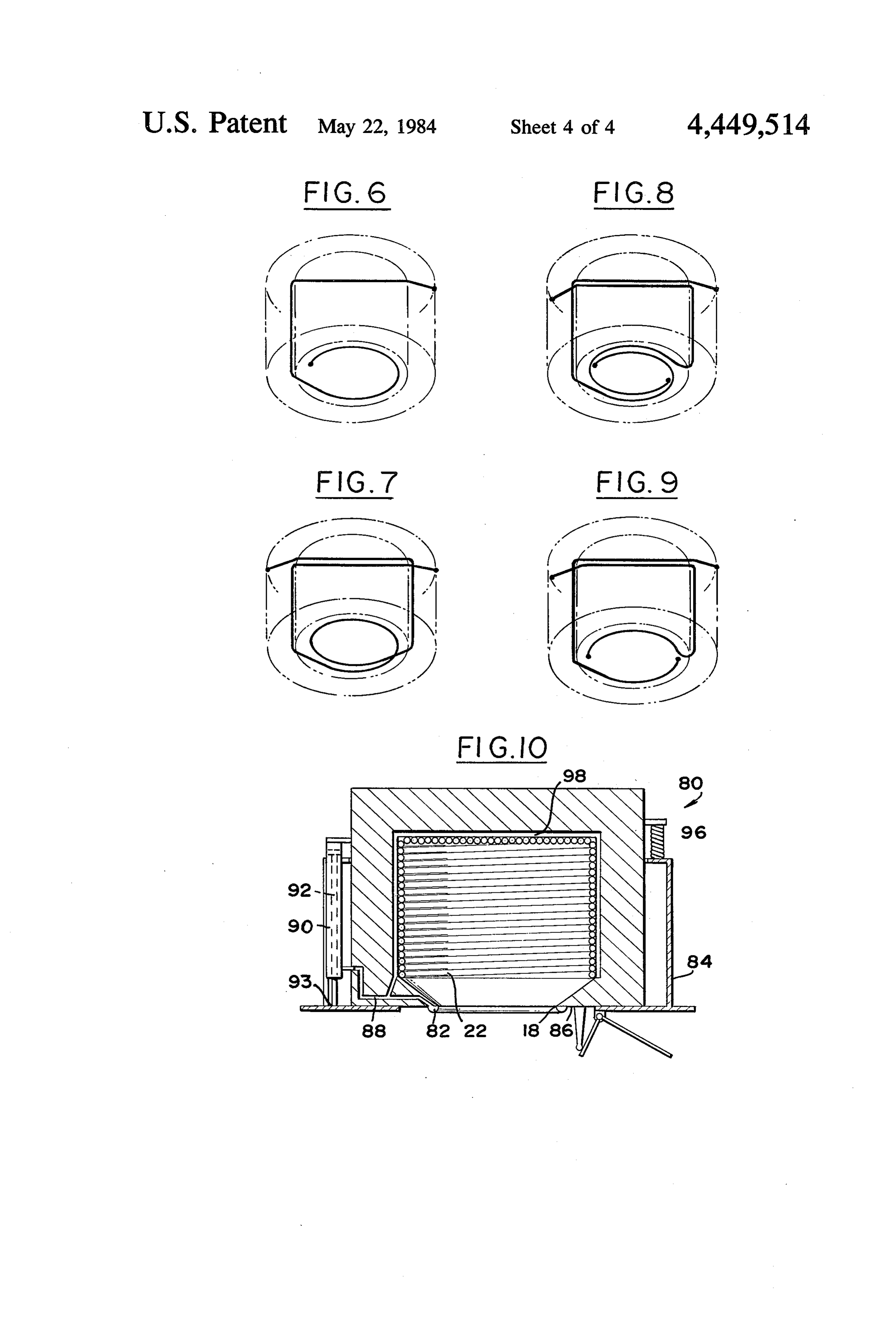
FIG. 4 is a view taken on the line 4-4 of FIG. 3.
Page 2drawing sheetscan →
Page 3drawing sheetscan →
Page 4drawing sheetscan →
Page 5drawing sheetscan →
Page 6scan →
SOLAR CONCENTRATOR PROTECTIVE SYSTEM BRIEF DESCRIPTION OF THE DRAWINGS FIG. 1 is a sectional side view of a solar concentrator
ORIGIN OF THE INVENTION system which includes the protective apparatus of the The invention described herein was made in the per present tion.
invention shown in solid lines in an open posi formance of work under a NASA contract and is sub FIG. 2 is a partial perspective view of the system of ject to the provisions of Section 305 of the National FIG. 1, shown in an open position in solid lines, and in Aeronautics and Space Act of 1958, Public Law 85-568 a closed position in phantom lines.
(72 Stat. 435; 42 USC 2457). 10 FIG. 3 is a more detailed sectional view of a portion BACKGROUND OF THE INVENTION of the system of FIG. 1.
FIG. 4 is a view taken on the line 4-4 of FIG. 3.
One type of solar collector includes a concentrator, FIG. 5 is a view in greater detail, of a portion of the such as a parabolic dish reflector, which forms a con system of FIG. 3.
centrated image of the sun onto the opening of a re 15 FIGS. 6through 9 illustrate various fuse wire config ceiver. The concentrated solar radiation heats tubes urations that can be used in the system of FIGS. 1 within the receiver chamber that carry water or other through 5. s working fluid. If the concentrated image of the sun FIG. 10 is a partial sectional view of a solar concen strikes the receiver face plate, due to a tracking failure trator system constructed in accordance with another or a major error in alignment, then the face plate may be 20 embodiment of the invention.
burned. Similarly, if working fluid in the receiver tubes DESCRIPTION OF THE PREFERRED is lost, or circulation stops because of a pump failure, EMBODIMENTS the tubes can be damaged because of overheating. A FIG. 1 illustrates a solar concentrator system 10 relatively simple apparatus that could protect the re ceiver against damage in the event of such failures, 25 which receiver includes a reflector dish concentrator 12 and a 16. The receiver has an opening 18 through while avoiding interference with normal operation of which concentrated solar radiation is received in a cav the concentrator system, would be of conconsiderable ity 20, to heat a group of tubes 22 through which a value. cooling fluid passes, as to turn such a fluid into steam for 30 generating electrical power. The concentrator 12 forms
SUMMARY OF THE INVENTION a concentrated image of the sun at a position 24 that is In accordance with one embodiment of the present even with the opening 18 of the receiver. If there were invention, a protective system is provided for use with a large tracking error or the tracker stopped function a solar concentrator, for protecting the receiver in the ing, the image would be concentrated on a face plate 26 event of tracking or other failure, which is relatively 35 of the receiver and burn it.
simple and which avoids interference with normal oper A shutter mechanism 30 is provided to safeguard the ation. The protective system includes a shutter mecha receiver face plate 26 from burning in the event of a nism, and apparatus for storing the shutter mechanism tracking error which causes the concentrated image of in an open configuration near the receiver during nor the sun to fall outside of the opening 18 of the receiver. mal operation. Upon the occurrence of a failure that. The mechanism includes a shutter frame 32 which could cause damage to the receiver from concentrated carries several shutter elements 34-36. Three guides 38 solar radiation, the apparatus moves the shutter mecha are mounted on the outside of the receiver to guide the nism away from the receiver opening and towards the shutter frame in movement toward and away from the concentrator, and closes the shutter mechanism at its dish concentrator 12. During normal operation of the position away from the receiver opening. As a result, 45 system, the shutter elements are stored in the open con solar radiation falling on the shutter mechanism is much figuration shown in solid lines in FIGS. 1 and 2. How less concentrated than it would be at the receiver open ever, when solar radiation deviates sufficiently to dam age the face plate 26, the shutter mechanism is operated ing, to avoid burning of the shutter mechanism. to pivot the four shutter elements to a closed configura The apparatus can include a low melting temperature tion, and to move them at a downward incline along the fuse extending immediately around the receiver open 50 axis ing, so that deviating concentrated solar radiation shutter towards 40 the concentrator 12. The fully closed mechanism is shown at 30A, with the shutter breaks the fuse. The fuse is also extended beside the coolant-carrying tubes in the receiver cavity. A mecha elements As such as 34A, 35A in a closed configuration.
shown in FIG. 3, each shutter element such as 34 nism responsive to breaking of the fuse can operate the 55 is pivotally mounted on a bearing 42 that is mounted on shutter mechanism to close it. The shutter mechanism the shutter frame 32. A cam follower 44 is fixed to the can includes a shutter frame movable by gravity away shutter element 34. The cam follower 44 engages a cam from the receiver, and carrying devices for moving 46 mounted on the receiver. As the shutter frame 32 shutter elements to a closed position as the shutter moves downwardly towards the concentrator, as to the frame moves under the force of gravity towards its position 32B, the cam follower 44 can pivot as to the closed position. The fuse can include a wire that nor position 44B to allow the shutter element to pivot mally supports the shutter frame from moving, but towards a closed position at 34.B. Even after the shutter which releases the shutter frame to move upon breaking elements are closed, the shutter frame continues to of the wire by the concentrated image of the sun. move, to the position 32A with the shutter elements in The novel features of the invention are set forth with 65 their fully closed position.
particularity in the appended claims. The invention will The sensing apparatus 50 for sensing when the con be best understood from the following description when centrated sun image has deviated far enough from the read in conjunction with the accompanying drawings. central position 24 to endanger the face plate 26, in 7 cludes a fuse wire 52. The wire 52 includes a portion 52a concentrator 12, from reaching any point on the face which extends in largely a circle around the receiver plate 26. . . . . . . . . . . . . . . . opening 18, so that the deviating sun image can heatithe Another source of danger to the solar concentrator fusewire 52 to melt and break it. The fuse wire includes system is damage to the receiver tubes 22 in the event a portion 52b that extends near the outside of the re that there is loss of working fluid or in the event of ceiver and another portion 52c which extends through a ; pump failure, so that the tubes overheat. The same shut passage 54 in the receiver. The fuse wire portion 52b is termechanism 30 can be used to cover the receiver attached at 56 to the shutter frame 32. So long as the opening in the event of such a failure, by constructing it to release the shutter frame upon overheating of the fuse wire is intact, it prevents the shutter frame 32 from 10 inside moving downwardly along the centerline 40 towards plishedwalls by of the receiver chamber. This is accom including the fuse wire portion 52c extending the concentrator to close the shutter mechanism. How ever, if any portion of the fuse wire, including the por of adjacent to the receiver tubes and in series with the rest tion 52a that extends around the receiver opening 18 or surroundsthe fuse wire, including the fuse wire portion 52a that the portion 52c, is broken, then tension in the fuse wire 15 52c is of a the receiver opening. The fuse wire portion material having a lower melting temperature drops and it cannot support the shutter frame 32. The than the receiver tubes, to melt before the tubes melt. fuse wire 52 then acts as a release means that releases FIGS. 6through 9 illustrate various configurations of the shutter frame to move downwardly to the position fuse wires for sensing tracking failure and coolant circu 32A to close the shutter mechanism. .
lation failure. FIG. 6 illustrates
As shown in FIG. 4, one end 60 of the fuse wire 52 is 20 configuration used in the system of FIGS. a single wire, full loop anchored to the face plate, and the wire portion 52a illustrates a single wire, double loop configuration. 1–5. Fig. 7 extends therefrom in a circle around the receiver open ing 18. At the other end of the fuse wire portion 52a is FIG. 8 illustrates a two wire, full loop configuration. FIG. 9 illustrates a two wire, half loop configuration.
a radially extending wire portion 52d that extends out FIG. 10 shows another solar concentrator protective and then up along the receiver. As shown in FIG. 5, the 25 system 80 which utilizes a sensing or fuse tube 82 of low fuse wire portion 52a which extends around the re melting temperature material such as aluminum and ceiver opening 18, is enclosed by a heat shield 66. The containing a pressured gas. The tube surrounds the heat shield prevents melting of the fuse if sunlight is applied for only a short period of time during a sun receiver opening 18, to release a shutter mechanism frame 84 in the event of tracking failure or coolant acquisition period when the concentrator is turned to 30 circulation failure that would otherwise burn the face point towards the sun. In one example, the face plate 26 plate 86 or coolant tubes 22. The tube 82 is connected is formed of copper, which melts at 1086 C., and the through a connecting tube 88 to a cylinder 90 contain shutter frame 32 is formed of steel which melts at above ing pressured gas. A piston 92 fixed to the shutter frame 1500 C. The fuse wire at 52a can be formed of alumi at 93, can move along the cylinder 90 only if the pres num which melts at about 500 C. ,' 35 sure therein drops. In the event of a tracking error, If the concentrated solar radiation dwells sufficiently concentrated solar radiation will melt a hole in the long on the face plate that the fuse wire portion 52a sensing tube 82, allowing gas to flow out of the cylinder melts, then the shutter frame 32 is released to begin 90, to allow the shutter frame 84 to move downwardly. moving at a downward incline. Three compressed An actuator 96 can be included to urge the shutter. springs 70 (FIG. 3) spaced about the apparatus, push the frame 84 to move down. An additional sensing tube 98 shutter frame to begin its movement, and further move lying adjacent to the receiver tubes 22, contains com ment continues under the force of gravity. It is possible pressed gas and is connected to the connecting tube 88 to use a long spring or other actuator that forces the that leads to the cylinder 90. In the event of overheating shutter frame to move along its entire travel path, al of receiver tubes 22, the sensing tube 98 will melt and though use of gravity to accomplish this simplifies the 45 release gas before, the receiver tubes 22 are severely apparatus. At the end of downward movement, the damaged. The sensing tubes could be utilized to contain flange 56 of the shutter frame encounters three stops 72 a vacuum or pressured gas.
spaced about the apparatus that prevent any further Thus, the invention provides a solar concentrator movement. During the downward movement, torsion protective system which shields the receiver from con springs 74 (FIG. 5) coupled to each of the shutters such 50 centrated solar radiation in the event of system failure, as 34, force the shutters to pivot towards a closed posi using a sensing and shuttering mechanism of relatively tion as the corresponding cam followers 44 move rela simple construction. The shutter mechanism is stored in tive to the: cams 46. - . . . . . . . . . an open configuration near the receiver and beside it to The use of shutter frame movement towards the re avoid blocking the opening of the receiver. Upon sys flector concentrator 12 (FIG. 1) to close the mecha 55 tem failure, the shutter mechanism moves towards the nism, not only provides a simple mechanism for closing concentrator and closes to block solar radiation from the shutter elements 34-37, but also avoids excessive the receiver opening or the region immediately there heating of the shutter elements. This is because the being about. Such movement results in the shutter elements image of the sun which is highly concentrated at 24, is closed at a position where only partially concen considerably less concentrated when it falls on the trated solar radiation is encountered, so that the shutter closed shutter elements at 34A-37A. The closed shutter elements themselves are not burned. The movement of mechanism at 30A should be spaced from the receiver the shutter element also enables a relatively simple opening 18 by at least the width of the receiver opening, mechanism to be utilized that moves the shutter ele as measured along the axis 40. For large tracking errors, ments to their closed position, using cams on the re wherein the focal point 24 would approach the periph 65 ceiver to operate cam followers on the shutter mecha nism. The sensing of the tracking error can be accom ery of the face plate 26, the positioning of the closed plished shutter mechanism away from the face plate also serves by an easily meltable sensor extending in a circle to block solar radiation reflected from most of the dish immediately about the receiver opening, such a fuse 8 wire or gas-filled tube. A similar sensor can be placed said fuse includes a wire of a material which melts at adjacent to the heat transfer tubes within the receiver to a lower temperature than the walls of said receiver close the shutter mechanism in the event of lack of that surround said receiver opening, and said circulation of working fluid to the tubes. means responsive to breaking of said fuse is con Although particular embodiments of the invention structed to apply tension to said wire and release have been described and illustrated herein, it is recog said shutter mechanism to close upon the loss of nized that modifications and variations may readily wire tension resulting from breaking of the wire. occur to those skilled in the art and consequently it is 5. The improvement described in claim 3 wherein: intended that the claims be interpreted to cover such said fuse includes a tube which extends about said modifications and equivalents. O 'receiver opening and which melts at a lower tem What is claimed is: perature than the walls of said receiver that sur 1. In a solar concentrator system which includes a round said receiver opening, said tube containing solar radiation receiver with an opening and a concen gas at a pressure different than that of the ambient trator which concentrates solar radiation onto said re atmosphere, and said means responsive to breaking ceiver opening, the improvement of a protective system 15 of said fuse is constructed to release said shutter for blocking solar radiation comprising: mechanism to close upon a change in gas pressure a shutter mechanism including at least one shutter, in said tube.
said mechanism moveable between open and 6. In a solar concentrator system which includes a closed configurations; and solar radiation receiver with an opening and a concen means for storing said shutter mechanism near said 20 trator which concentrates solar radiation onto said re receiver and in an open configuration to avoid ceiver opening, the improvement of a protective system blocking the receiver opening, and for moving said for blocking solar radiation comprising:
shutter mechanism toward said concentrator to a a shutter mechanism including at least one shutter, second position spaced from said receiver opening said mechanism moveable between open and by at least about the width of said receiver opening, 25 closed configurations; and as measured along an imaginary centerline that means for storing said shutter mechanism near said connects the middle of said concentrator and said receiver opening, and closing said shutter mecha receiver and in an open configuration to avoid nism and holding it closed at said second position, blocking the receiver opening, and for moving said shutter mechanism toward said concentrator to a whereby to reduce the concentration of solar radia 30 second position and closing said shutter mechanism tion on the shutter in the closed configuration. and holding it closed at said second position; 2. In a solar concentrator system which includes a said shutter mechanism includes a shutter frame solar radiation receiver with an opening and a concen moveable toward said concentrator and a plurality trator which concentrates solar radiation onto said re ceiver opening, the improvement of a protective system 35 of shutter elements pivotally mounted on said for blocking solar radiation comprising: frame to pivot between open and closed positions, a shutter mechanism releaseable to move from an each element including a cam follower, said shutter open configuration to a closed configuration; and mechanism also including a plurality of cams means for releasing said shutter mechanism including mounted on said receiver and positioned to pivot a wire having a fuse portion extending around the said cam followers to close said shutter elements as receiver opening so the fuse portion can be broken said frame moves toward said concentrator. by concentrated sunlight falling thereon, and solar 7. In a solar concentrator system which includes a means responsive to breaking of said fuse portion radiation receiver with an opening and a concen for releasing said shutter mechanism to move to trator ceiver which concentrates solar radiation onto said re opening, the improvement of a protective system
3. In a solar concentrator system which includes a fora blocking shutter solar radiation comprising:
mechanism releaseable to move from an light receiver with an opening and a concentrator open configuration to a closed configuration; which concentrates solar radiation onto said receiver opening, the improvement of a protective system for said receiver includes a chamber and a plurality of blocking solar radiation comprising: 50 tubes for carrying cooling fluid positioned at the a shutter mechanism which includes a plurality of inside wall of said chamber; and shutter elements moveable between a closed posi means for releasing said shutter mechanism including tion to block said receiver opening against the a fuse of lower melting temperature material than passage of solar radiation from said concentrator said tubes lying adjacent to said chamber inside and an open position to allow such passage of solar 55 walls, so the fuse is melted when cooling fluid does radiation; and not flow at a sufficient rate through said tubes, means responsive to concentrated solar radiation while concentrated sunlight heats them, and means from said concentrator, deviating from said re responsive to breaking of said fuse for releasing ceiver opening, for repositioning said shutter said shutter mechanism.
mechanism from said open position to said closed 8. In a solar concentrator system which includes a position, said repositioning means including a low solar radiation receiver with an opening and a concen temperature melting fuse extending immediately trator which concentrates solar radiation onto said re around said receiver opening so that deviating ceiver opening, the improvement of a protective system concentrated solar radiation melts said fuse to for blocking solar radiation comprising: break it, and means responsive to breaking of said 65 a main frame supporting said concentrator and re fuse for moving said shutter mechanism to said ceiver with said receiver above said concentrator closed position. when said concentrator faces upward toward the 4. The improvement described in claim 3 wherein: sky, said receiver having a guideway;
Page 9scan →
a shutter mechanism including a shutter-frame move ceiver overheating for releasing said shutter frame able along said guideway, said main frame holding to move along said guideway; said guideway to confine said shutter frame to said shutter mechanism including a plurality of shut ter elements and cam elements, some of said ele movement toward and away from said concentra ments mounted on said shutter frame and other elements mounted on said receiver, said cam ele retainer means connected between said main frame and said shutter frame for supporting said shutter ments positioned to move said shutter elements from open to closed positions as said shutter frame frame against moving along said guideway, said moves down along said guideway. retainer means responsive to the beginning of re O is . . ..
Provenance
- Collection
- Patents citing this work
- Pages
- 9
- Method
- pdftotext (the PDF's own text layer) + pdftoppm 300dpi page scans
- Patent office record
- patents.google.com →
- Source
- Google Patents citing-documents table
- Assignee
- The United States Of America As Represented By The Administrator Of The National Aeronautics And Space Administration
- Published
- 1984-05-22
- Transcribed from
- patentimages.storage.googleapis.com →