

patent · US4454850A
Apparatus and method for energy conversion
19 June 1984
Text
Page 1bibliographic recordscan →
United States Paterat (19)
Horvath
(54) APPARATUS AND METHOD FOR ENERGY
CONVERSION
Inventor: Stephen Horvath, St. Ives, Australia 73 Assignee: Beeston Company Limited, Hong
Kong
Related U.S. Application Data 63 Continuation of Ser. No. 56,863, Jul. 12, 1979, aban doned.
30 Foreign Application Priority Data
Jul. 14, 1978 IAU Australia .............................. PD int. Cl. ............................................. F02M 27/06 52 U.S. C. .................................... 123/537; 123/527;
3,110,294 11/1963 Nyman ................................ 123/536 3,362,883 1/1968 Wright ... 123/DIG. 12
4,052,139 10/1977 Paillaud et al. ..................... 123/1 A 4,069,665 1/1978 Bolasny ........... ... 123/538 4,304,627 12/1981 Lewis .................................. 376/148
E22. X NASN
area
FOREIGN PATENT DOCUMENTS
OTHER PUBLICATIONS
Weidner and Sells, Elementary Modern Physics-Alter nate Second Edition, Feb. 1974, pp. 401-402.
Plasmas and Controlled Fusion, David J. Rose and
Primary Examiner-Charles J. Myhre
Assistant Examiner-Andrew M. Dolinar
Attorney, Agent, or Firm-Biebel, French & Nauman
Process and apparatus for liberation of energy by con trolled nuclear fusion reaction involving isotopes of hydrogen gas. Highly ionized hydrogen gas containing a higher proportion of deuterium than in naturally oc curring hydrogen is pressurized, together with an oxi dizing gas within combustion chamber of reciprocating piston and cylinder engine. An electrical discharge within the combustion chamber causes generation of heat by atomic dissociation and exothermal recombina tion of hydrogen atoms and electrical excitation of ion ized gas. Ionized deuterium in the hydrogen gas under goes a nuclear fusion reaction with consequent libera tion of heat energy and remaining hydrogen gas burns in the oxidizing gas to provide control on fusion reac tion. Apparatus for producing ionized hydrogen gas in appropriate form by treatment of normal industrial hydrogen gas is disclosed, and also gas mixing apparatus for mixing the ionized hydrogen with atmospheric air as the oxidizing gas.
2 Claims, 28 Drawing Figures
NNNNNNAN
GNS
s VAX
Drawings

Page 2drawing sheetscan →
Page 3drawing sheetscan →
Page 4drawing sheetscan →
Page 5drawing sheetscan →
Page 6drawing sheetscan →
Page 7drawing sheetscan →
Page 8drawing sheetscan →
Page 9drawing sheetscan →
Page 10drawing sheetscan →
Page 11drawing sheetscan →
Page 12drawing sheetscan →
Page 13drawing sheetscan →
Page 14drawing sheetscan →
Page 15drawing sheetscan →
Page 16drawing sheetscan →
Page 17drawing sheetscan →
Page 18scan →
means to produce ionised hydrogen gas,
APPARATUS AND METHOD FOR ENERGY means to introduce said ionised hydrogen gas to CONVERSION gether with an oxidising gas into said chamber; and means to create an electrical discharge within the
This is a continuation of application Ser. No. 56,863 5 chamber.
filed July 12, 1979, now abandoned. Said fuel burning plant may be in the form of an BACKGROUND OF THE INVENTION internal combustion engine. More particularly this en gine may be of the reciprocating piston and cylinder
This invention provides a process and apparatus by type in which case the combustion chamber may be one means of which energy may be liberated by a controlled 10 of a plurality of such chambers defined between pistons nuclear fusion reaction involving isotopes of hydrogen and a cylinder head of the engine. gaS. The ionised hydrogen gas may be produced by con Nuclear fusion reactions are known to be the energy version of water by a process involving electrolysis and source in two widely different situations. At one ex radiolysis in which the electrolyte is irradiated with treme, relatively slow reactions produce the energy of 15 short wavelength electromagnetic radiation, more spe the sun and other stars and at the other extreme re cifically radiation of wavelength less than 10-10 meters. peated nuclear fusion reactions are responsible for the One suitable method and apparatus for producing hy explosive power of thermonuclear weapons. In both drogen gas in suitable form for the present invention, as cases, however, the reactions proceed at extremely high temperatures and the liberation of energy is uncon 20 well as oxygen which can serve as at least part of the oxidising gas in the process of the present invention, is trolled. By the present invention it is possible to bring described in U.S. Pat. No. 4,107,008. about a nuclear fusion reaction under conditions which enable energy to be released in a controllable manner. Alternatively, hydrogen gas in a form suitable for use in accordance with the present invention can be pro
SUMMARY OF THE INVENTION 25 duced by conversion of normal hydrogen gas prepared According to the invention there is provided a pro by conventional industrial processes, the conversion requiring irradiation of the gas with short wavelength cess wherein ionised hydrogen gas is introduced to electromagnetic radiation, preferably in the presence of gether with an oxidising gas into a combustion chamber an intense magnetic field. and an electrical discharge is created within the com bustion chamber to initiate combustion of the hydrogen 30 plained one particularinvention In order that the may be more fully ex with the oxidising gas. Preferably the electrical dis detail with reference toembodimentthe will be described in accompanying drawings.
charge is such as to cause dissociation of hydrogen molecules in the chamber to hydrogen atoms which BRIEF DESCRIPTION OF THE DRAWINGS atoms recombine exothermally to generate heat in the
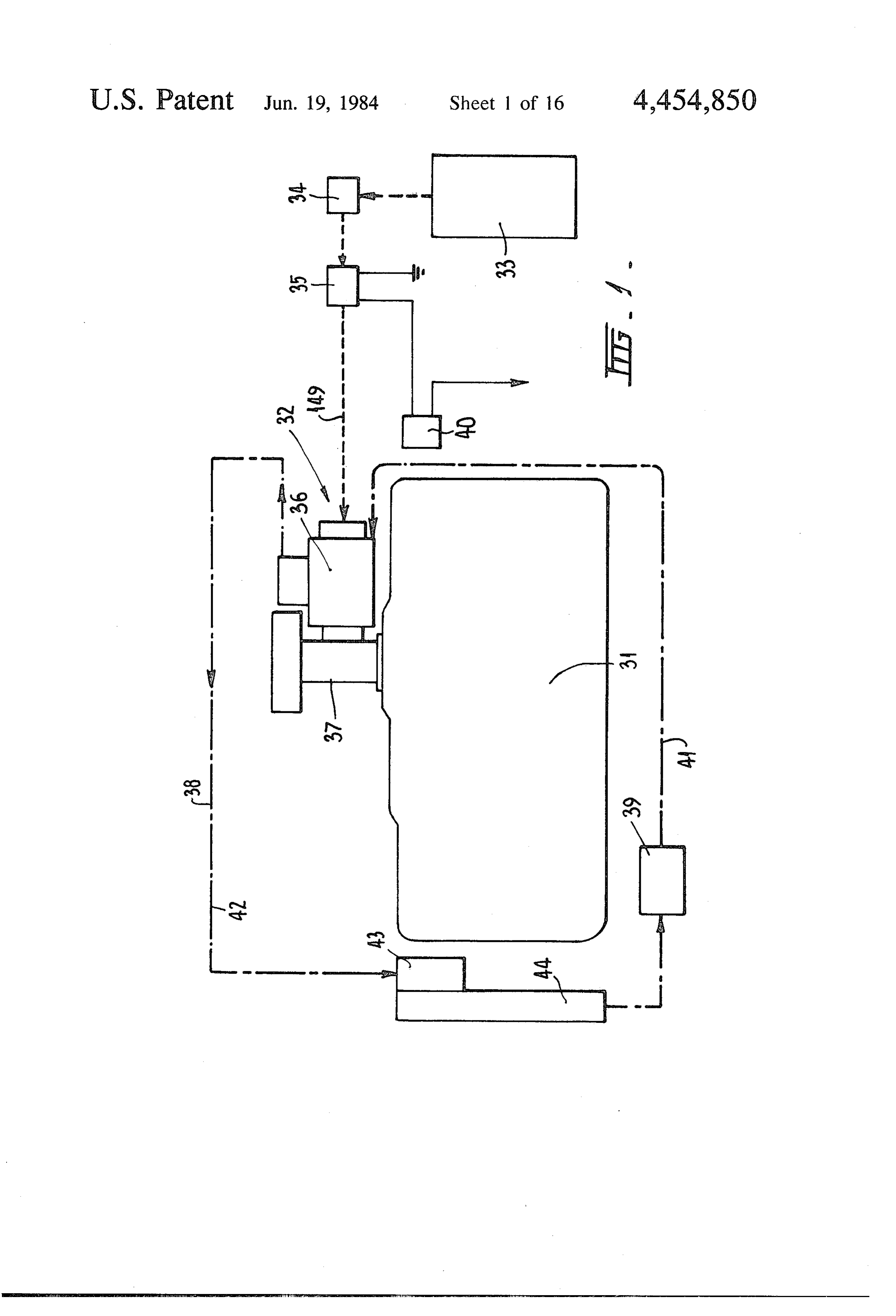
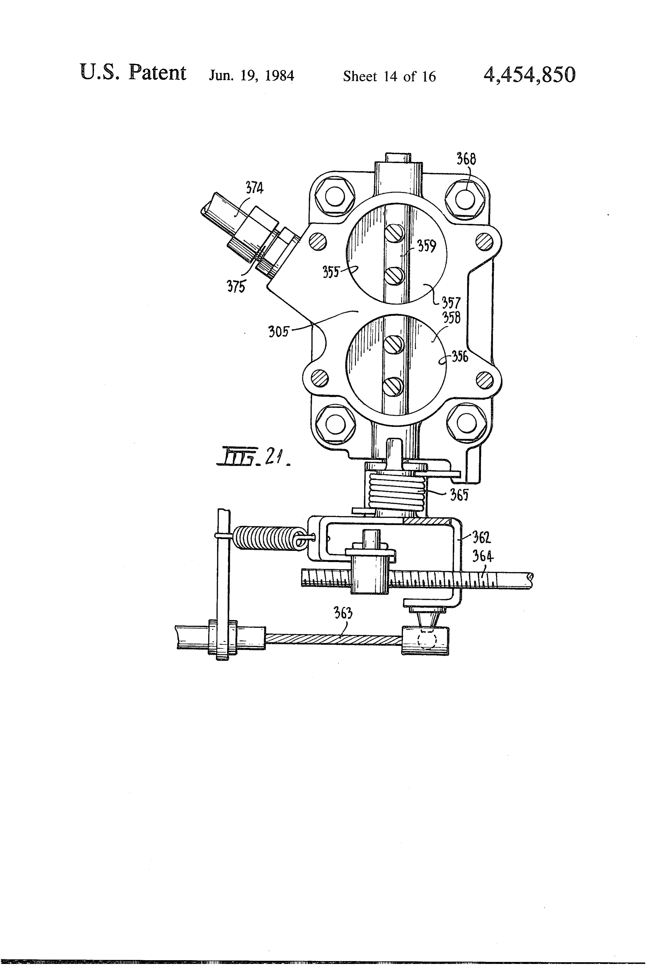
FIG. 1 is a diagrammatic plan view of an internal chamber in addition to that generated by the combus 35 combustion tion of hydrogen. engine fitted with a fuel supply system Preferably, too, the heat generated in the chamber is which incorporates a hydrogen gas conversion appara sufficient to cause ionised deuterium in the hydrogen tus for converting normal commercially available hy gas to undergo a nuclear fusion reaction with conse drogen to a form suitable for use in accordance with the quent liberation of heat energy. For this purpose it is present invention and a gas mixer for mixing the con preferred that the ionised hydrogen introduced into the verted hydrogen gas with air to provide a fuel mixture combustion chamber have a higher proportion of deute for the engine;
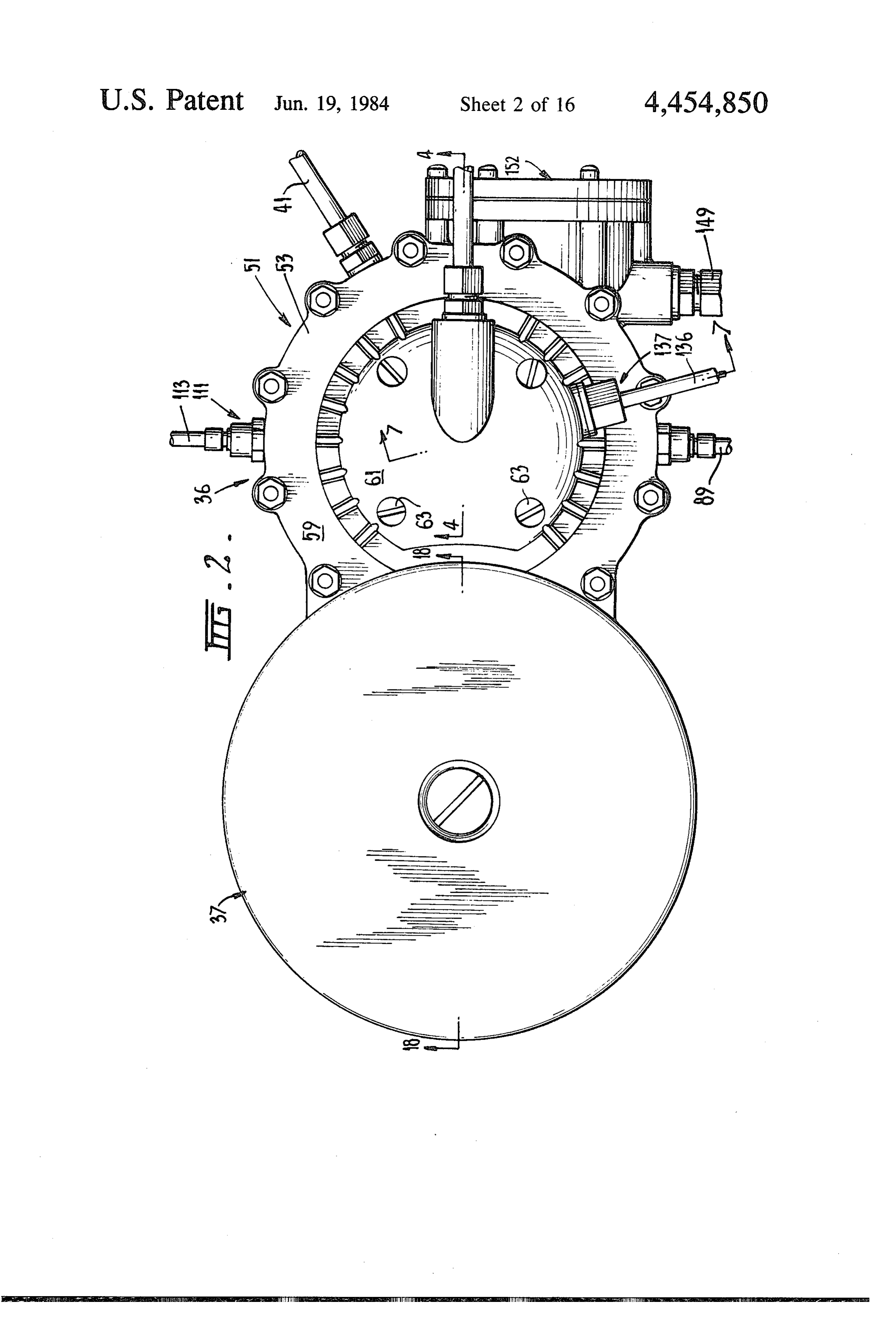
rium than in naturally occurring hydrogen. The inven FIG. 2 is a plan of the hydrogen conversion apparatus tion accordingly also provides a process comprising the and gas mixer;
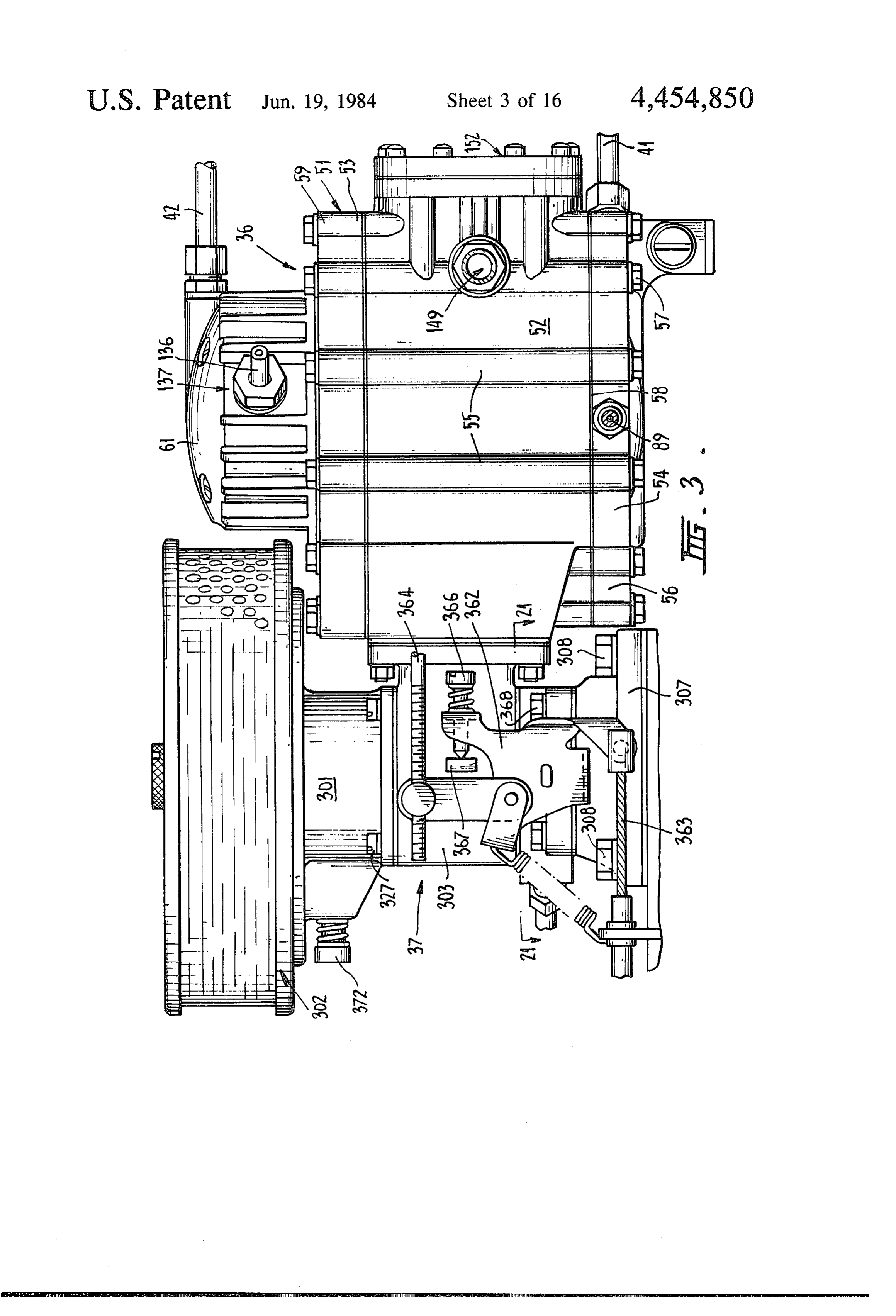
steps of: 45 FIG. 3 is a side elevation of the gas conversion appa producing ionised hydrogen gas containing a higher ratus and gas mixer;
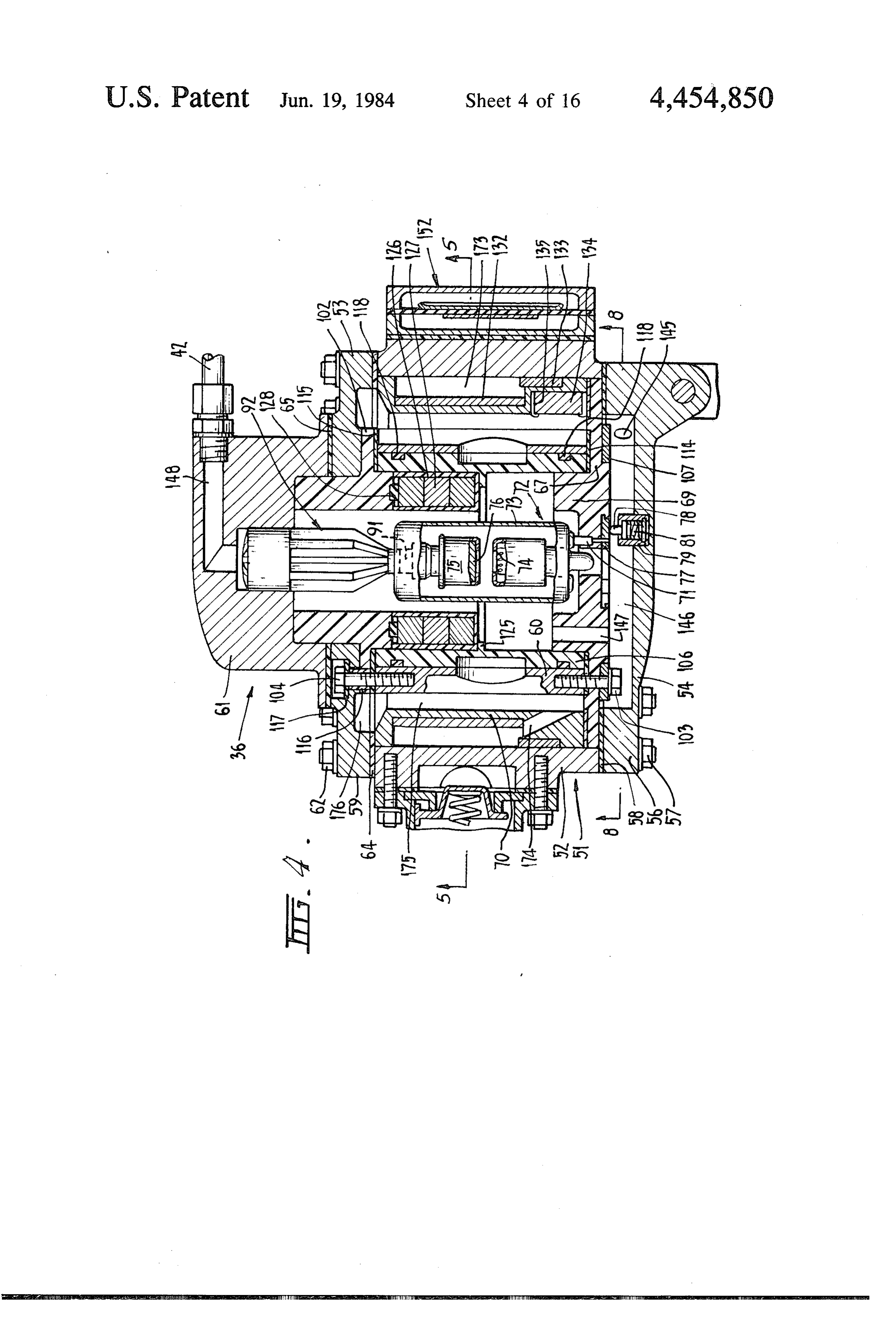
proportion of deuterium than in naturally occurring FIG. 4 is a vertical cross-section through the horizon hydrogen, tal conversion apparatus taken generally on the line introducing said ionised hydrogen gas together with 4-4 in FIG. 2;
an oxidising gas into a combustion chamber, 50 FIG. 5 is a horizontal cross-section through the hy closing the combustion chamber, and drogen conversion apparatus taken generally on the line creating within the combustion chamber an electrical 5-5 in FIG. 4;
discharge to cause generation of heat within the cham FIG. 6 is a scrap cross-section on the line 6-6 in ber by atomic dissociation and exothermal recombina FIG. 5;
tion of hydrogen atoms as well as by combustion of 55 FIG. 7 is a scrap cross-section generally on the line hydrogen with the oxidising gas whereby to cause io 7-7 in FIG. 2;
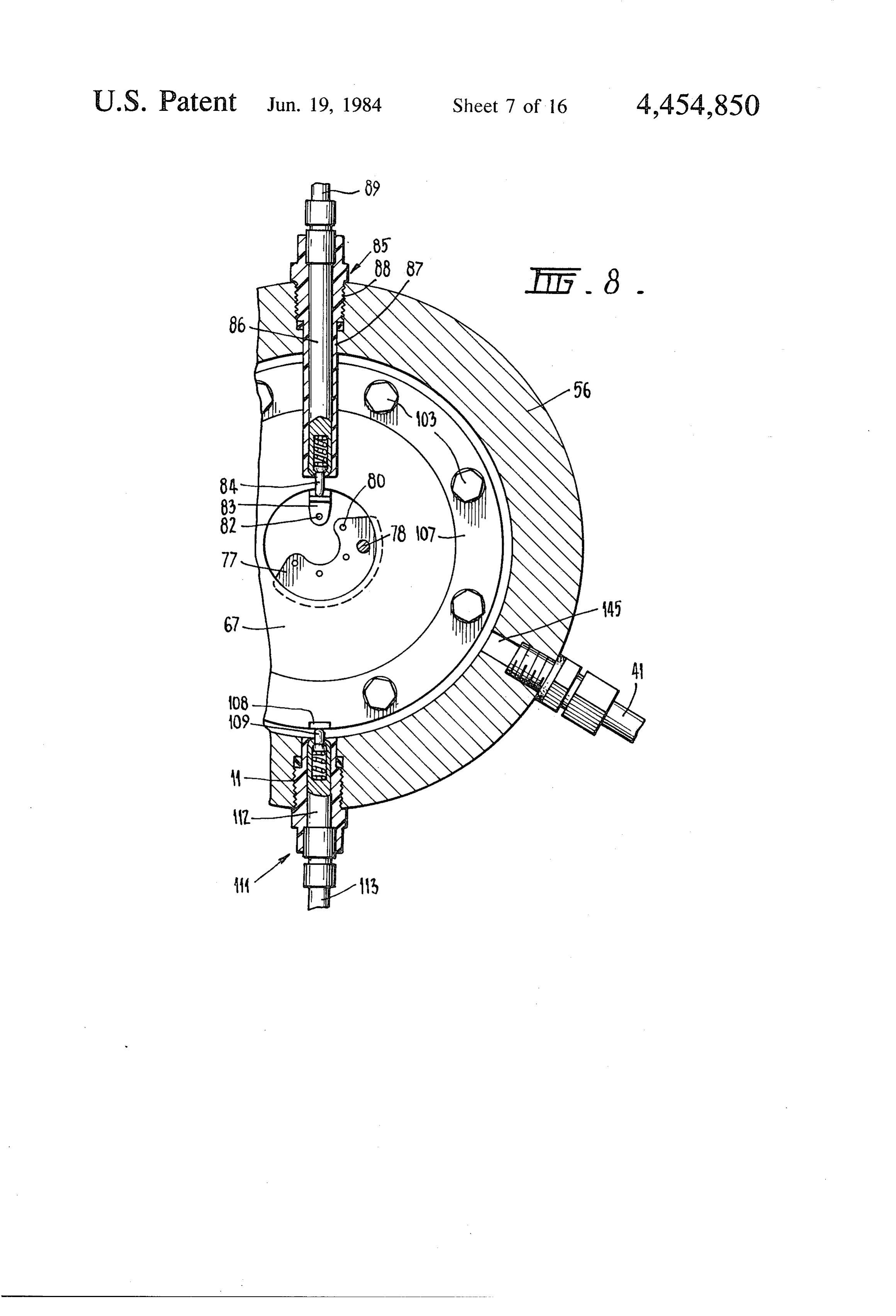
nised deuterium in the hydrogen gas to undergo a nu FIG. 8 is a cross-section generally on the line 8-8 in clear fusion reaction with consequent liberation of heat FIG. 4;
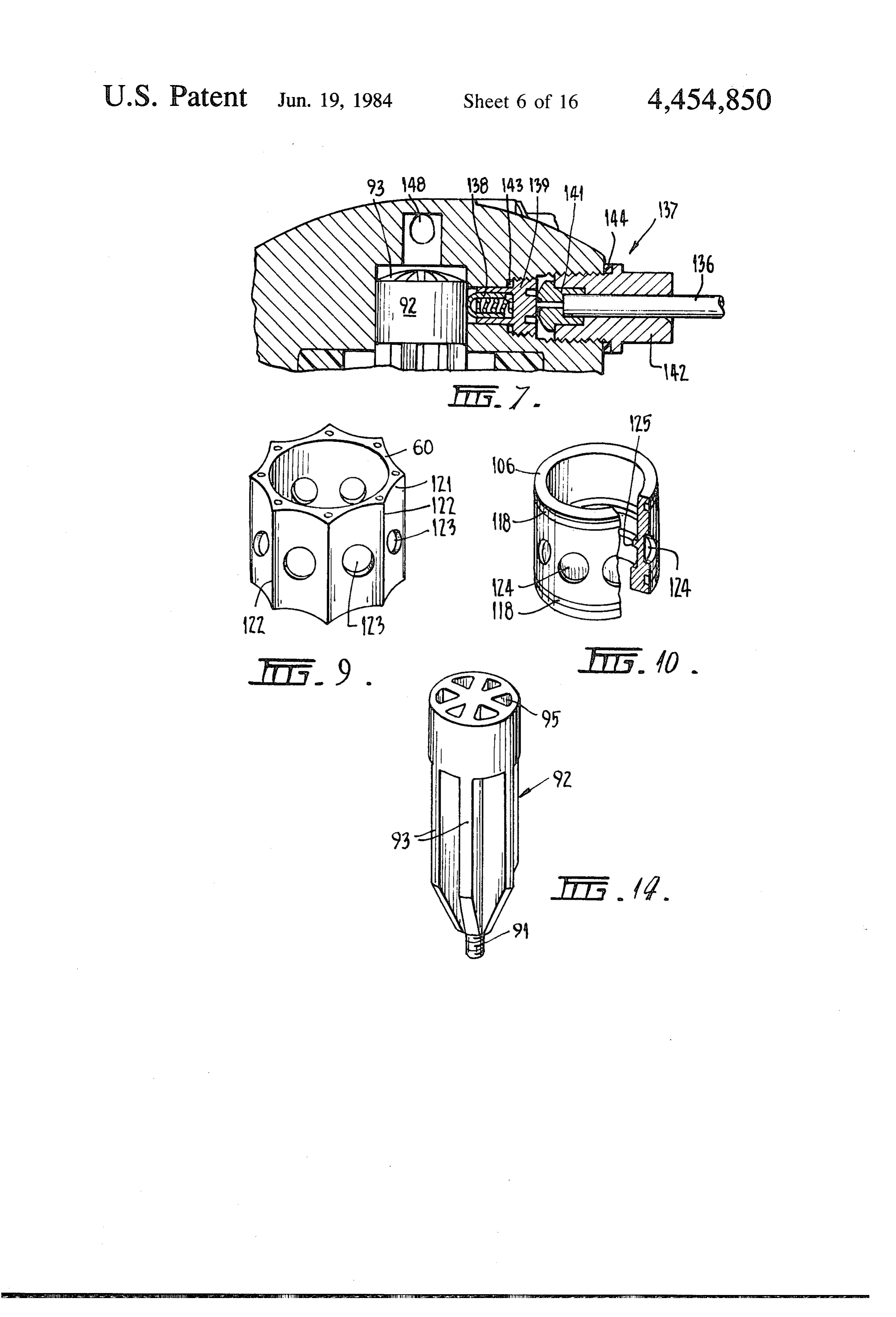
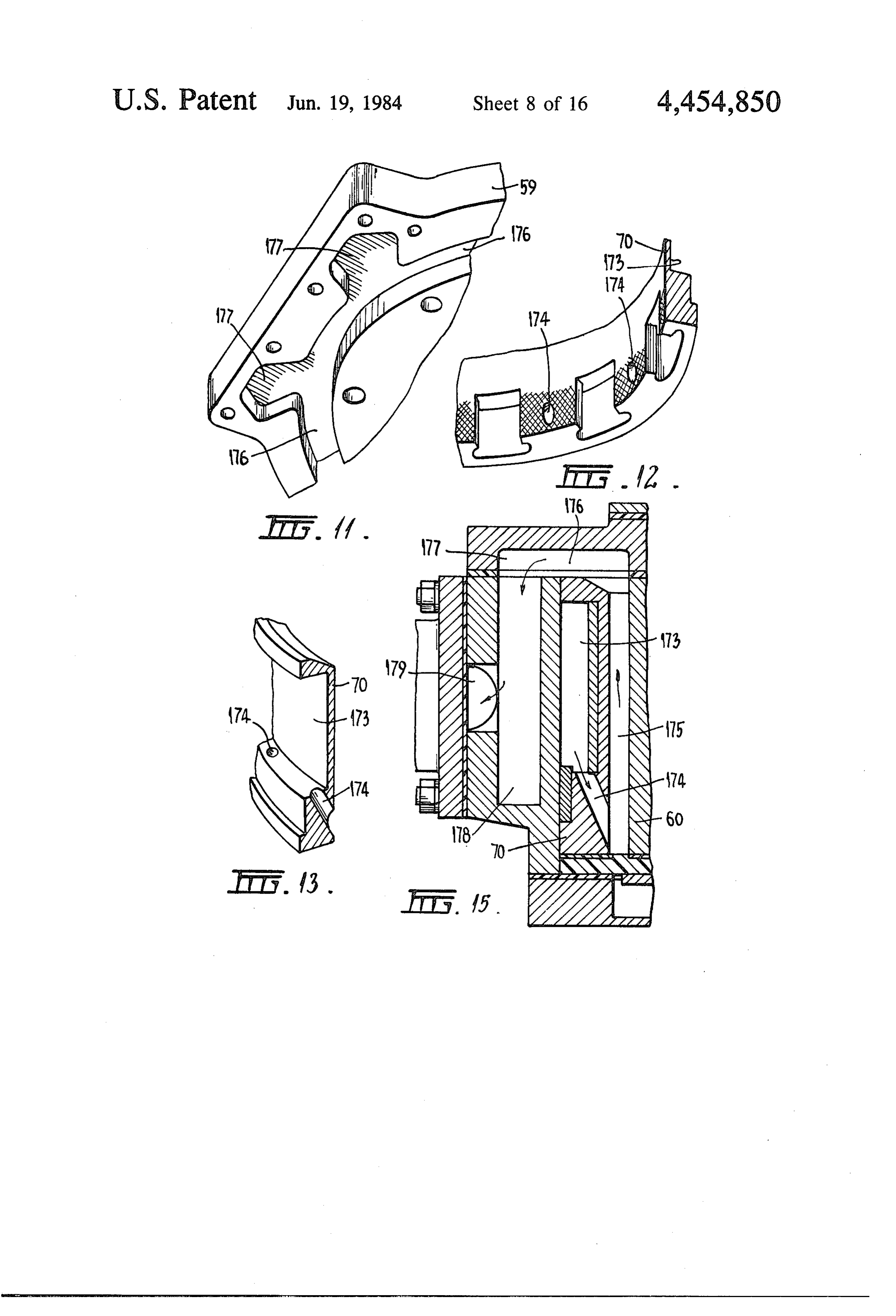
energy. FIGS. 9 to 4 are perspective views showing details Preferably, the ionised hydrogen gas and oxidising of components in the hydrogen conversion apparatus; gas are pressurised to above atmospheric pressure in FIG. 15 is a vertical cross-section taken generally on said combustion chamber before combustion. More the line 15-15 in FIG. 5;
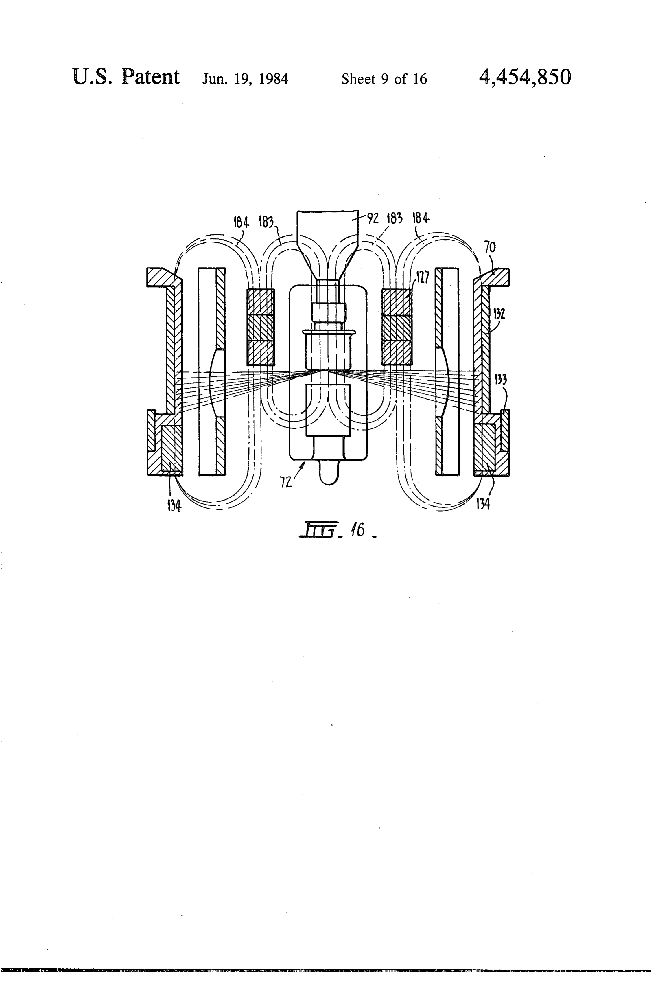
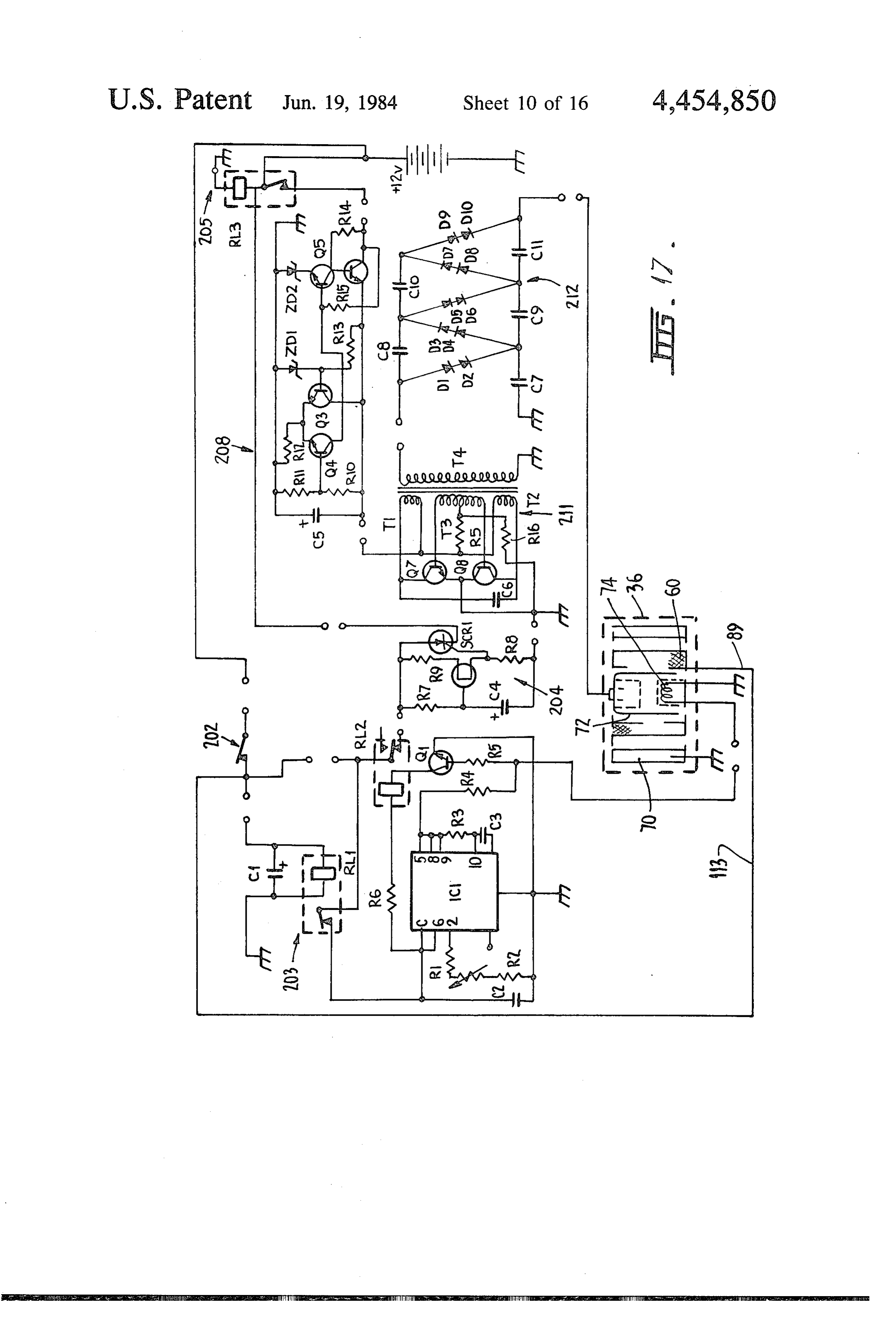
particularly these gases should be pressurised to a pres FIG. 16 is a vertical cross-section through the vital sure of at least 60 p.s.i. components of the hydrogen conversion apparatus and The invention also provides apparatus comprising, in 65 illustrates diagrammatically paths of electromagnetic combination; radiation and magnetic fields within the device; gaseous fuel burning plant having a combustion FIG. 17 is an electric circuit diagram for the appara chamber to receive gaseous fuel, tus illustrated in FIGS. i to 6;
Page 19scan →
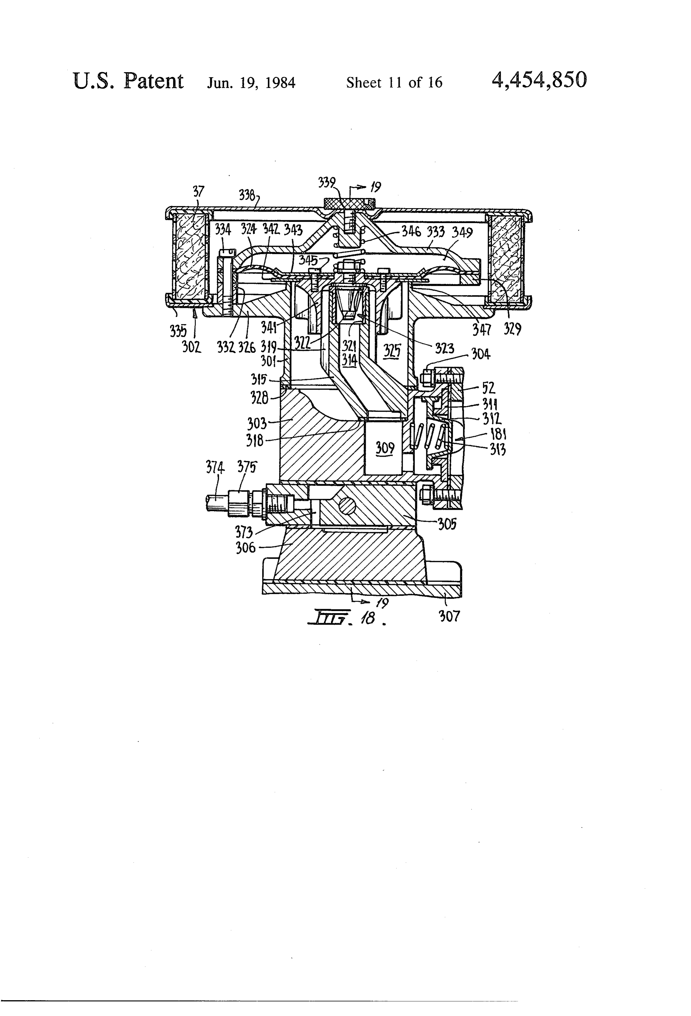
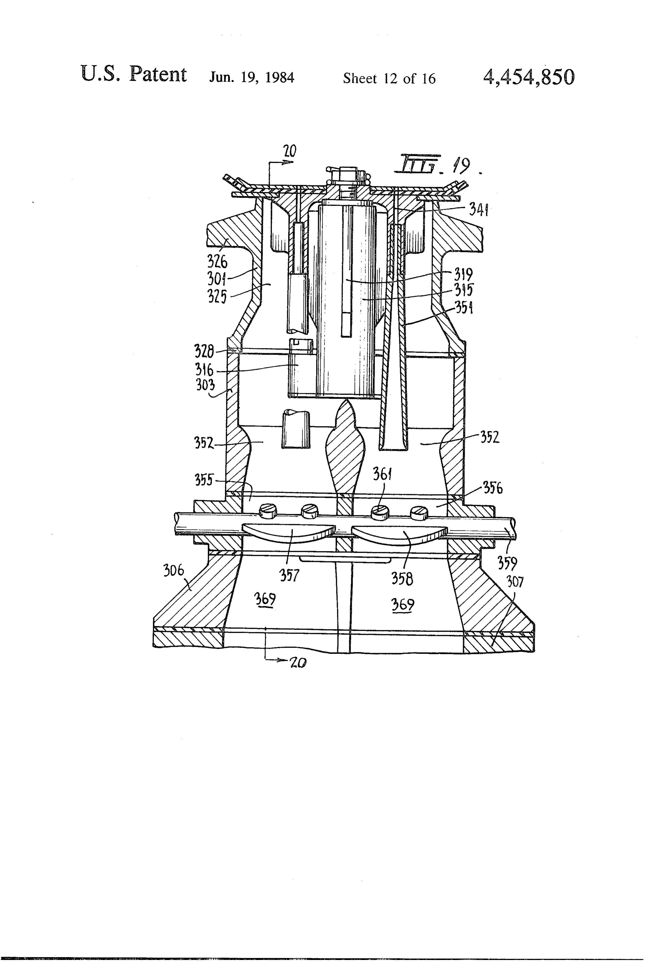
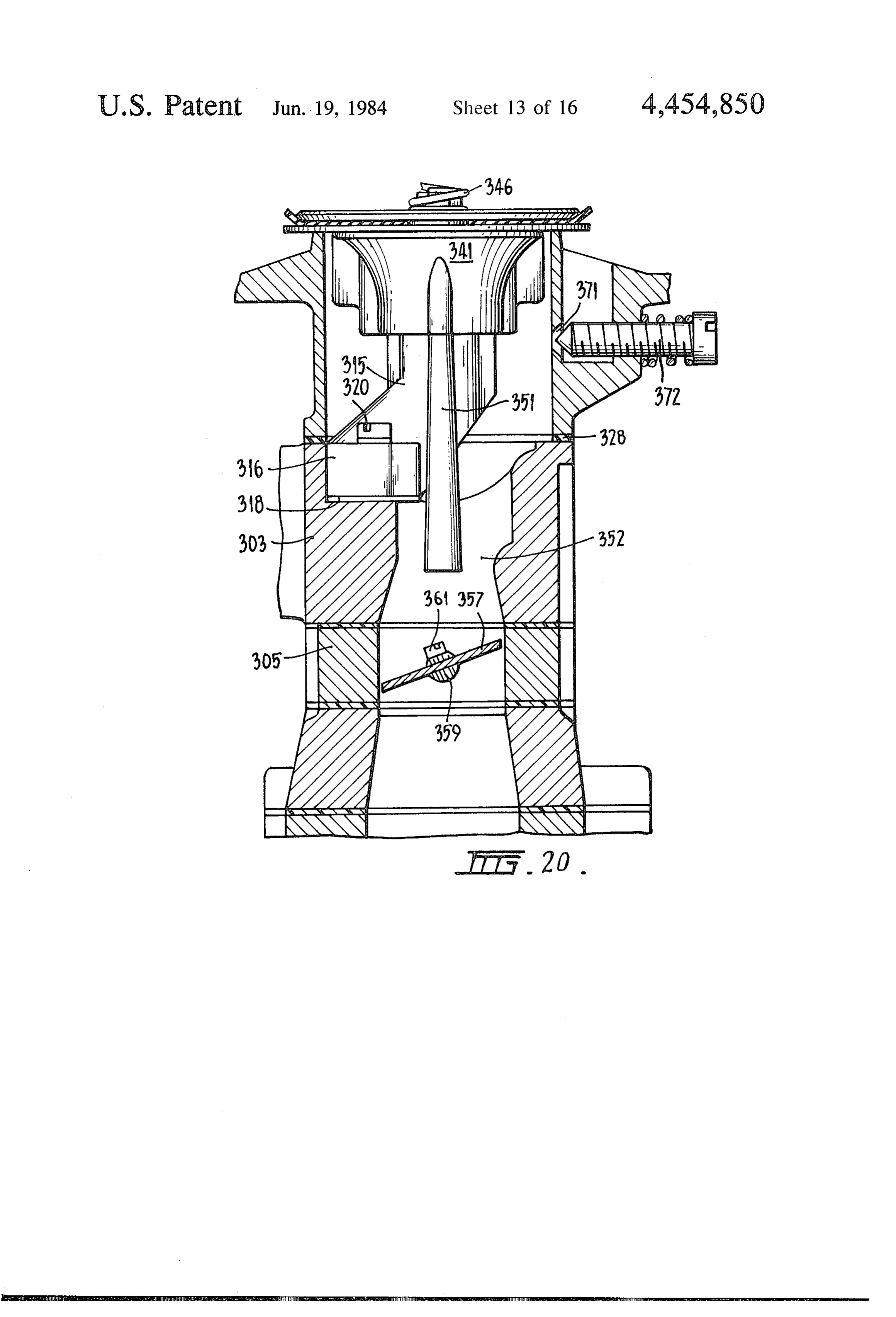
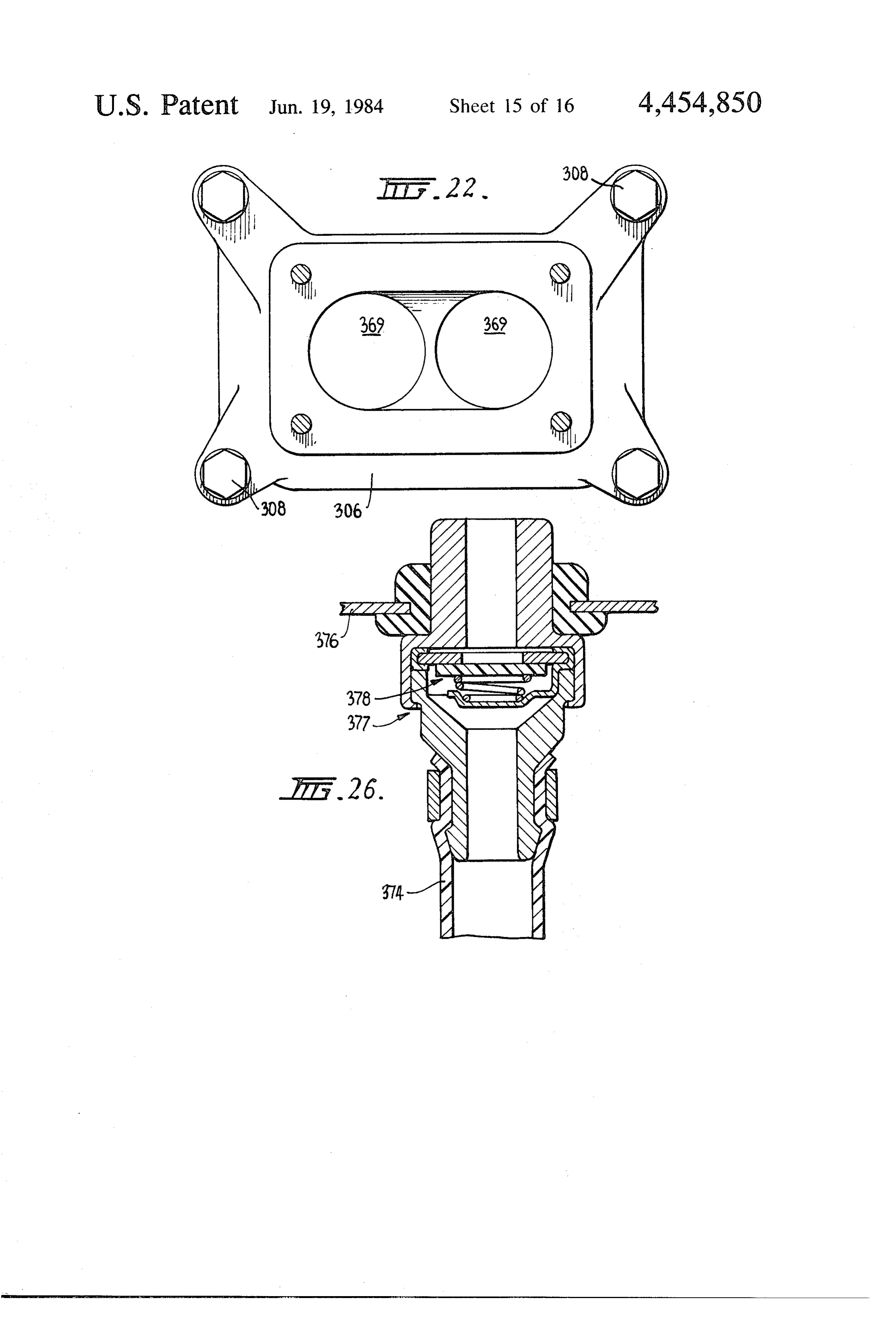
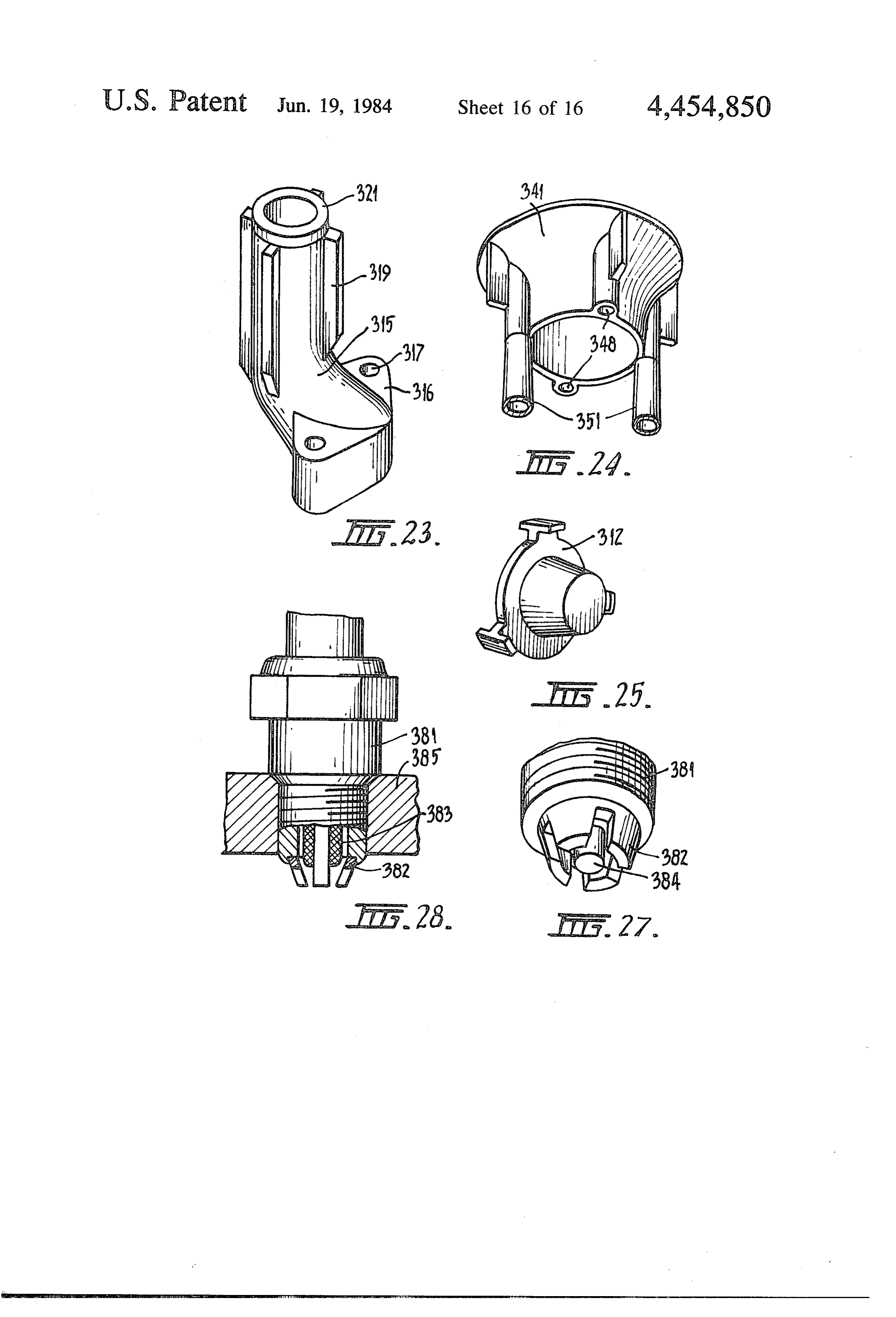
F.G. 18 is a vertical cross-section through the gas Top closure 53 is comprised of a non-magnetic stain mixer taken generally on the line 18-18 in FIG. 2; less steel top plate 59 and a plastic cover 61. Top plate FIG. 9 is a cross-section on the line 19-19 in FIG. 59 is fastened to the upper end of casing body 52 by ten i8; clamping bolts 62 which screw into tapped holes in the FIG. 20 is a cross-section generally on the line 20-20 casing body and plastic cover 61 is fastened to top plate in FIG. 19, 59 by four fastening screws 63 so as to cover a central FIG. 21 is a plan view of a lower section of the gas opening in the top plate. The interface between top mixer broken away from the upper section along the plate 59 and casing body 52 is sealed by an annular interface 21-21 of FIG. 3; gasket 64 and the interface between the top plate and FIG. 22 is a plan of a lower body part of the gas 10 plastic cover 61 is sealed by an annular gasket 65. mixer; In the gas conversion apparatus, the hydrogen gas is FIGS. 23, 24 and 25 are perspective views of compo passed upwardly through an annular chamber formed nents in the gas mixer; between a tubular electrical anode 60 and a tubular FIG. 26 illustrates the connection of an oil vapour cathode 70 surrounding the anode. Cathode 70, which extraction tube to the valve case of the engine; and 15 will be described in detail below, fits closely within the FIGS. 27 and 28 illustrate an electrical discharge peripheral wall of casing body 52. Its upper end engages device fitted to the engine. gasket 64 and its lower end provides an abutment for the outer rim of a plastic bottom disc 67 which is held
DESCRIPTION OF THE PREFERRED clamped to the bottom of the cathode by the bottom EMBODIMENT 20 plate 56. A sealing gasket 68 is located between the FIG. 1 shows diagrammatically an internal combus bottom end of the cathode assembly and the plastic tion engine 31 fitted with a fuel supply system denoted bottom disc 67.
generally as 32. The fuel supply system comprises a gas Plastic bottom disc 67 has a central boss portion 69 tank 33 to receive industrial hydrogen gas. Gas from 25 which pins 71 is provided with five socket holes to receive five of a shortwave length electromagnetic radiation tank 33 passes through a primary pressure regulator 34 tube denoted generally as 72 which is disposed centrally and a solenoid valve 35 which is contracted by a vac within the casing. Radiation tube 72 comprises a par uum operated switch 40 sensitive to the vacuum pres tially evacuated glass-walled envelope 73 which houses sure in the fuel intake manifold of the engine. The gas a shielded filament winding 74 then passes to a hydrogen gas conversion apparatus 36 30 a tungsten insert 76 providing aand an anode 75 having flat target surface. One which converts it to highly ionized hydrogen gas hav end of filament winding 74 is electrically connected to ing a significantly high proportion of deuterium. The one of the five terminal pins 71 to provide a positive thus converted gas passes to a gas mixer 37 wherein it is current connection. The other end of filament 74 is mixed with atmospheric air to produce a gas mixture connected to all of the remaining four pins 71 to provide which is introduced as fuel into the engine.
The engine is of the reciprocating piston and cylinder a common negative or earth connection.
As indicated in FIGS. 4 and 8, the four earthing pins type. It may be a conventional automobile engine in of tube 72 engage holes 80 in a horse-shoe shaped metal which the usual hydrocarbon fuel delivery system (car plate 77 fitted within a recess in the underside of plastic buretter or fuel injection system) is replaced by the bottom disc 67. Plate 77 is engaged by a spring-loaded hydrogen fuel supply system and which is fitted with electrical contact plunger 78. Contactor 78 is mounted special electrical discharge devices to be described be in a metal tube 79 carrying the loading spring 81 and low. fitted to bottom cover plate 56 to provide an earthing The hydrogen gas conversion apparatus 36 requires a connection through the outer casing. The single posi forced flow oil circulation system and this system is tive electrical supply pin 71 of tube 72 engages a hole 82 indicated generally as 38 in FIG. 1. It incorporates a 45 in a metal tag 83 on plastic bottom disc 67 and this tag pump 39 which delivers oil through a pipe 41 to the is engaged by a spring-loaded contact plunger 84 car bottom of conversion apparatus 36. As will be described ried at the inner end of an electrical connector assembly below, the oil flows upwardly through the conversion 85 which extends radially inwardly through the outer apparatus 36 and thence through a further duct 42 to an casing. Connector assembly 85 comprises a central con oil reservoir 43 and oil cooling radiator 44 and back to 50 ductor 86 formed of gold plated brass housed within a the pump for recirculation. plastic sheath 87 having an external screw threaded As seen most clearly in FIGS. 2 and 3 the hydrogen portion 88 to screw into a tapped opening in the side of gas conversion apparatus 36 and the gas mixer 37 may the casing. Conductor 86 is connected to an electrical conveniently be constructed as a single assembly which supply lead 89 which provides positive DC voltage to bolts directly on to the head of engine 31. 55 the filament winding 74 of the radiation tube. The construction of gas conversion apparatus 36 is The anode 75 of the radiation tube is connected by a fully illustrated by FIGS. 2 through 12. It comprises an screw connection 91 to a gold-plated brass terminal 92 outer casing 51 having a cast aluminium tubular body 52 the construction of which is most clearly seen in FIGS. and top and bottom closures 53, 54. The peripheral wall 4 and 14. This terminal serves as an electrical connector of the casing incorporates cooling fins 55 and the top through which to supply high voltage to the anode of and bottom closures are formed with extensions of these radiation tube 72 and also as a heat sink for the radiation fins tube. The lower part of terminal 92 has circumferen Bottom closure 54 is comprised of a non-magnetic tially spaced longitudinal fins 93 whereas the upper part stainless steel bottom plate 56 which is clamped to the has a smooth cylindrical periphery 94 and a series of six bottom end of casing body 52 by means of clamping 65 longitudinally extending internal passages 95 which bolts 57 which screw into tapped holes in the body wall. extend downwardly through the upper portion to com The interface between bottom plate 56 and body 52 is municate with the spaces between the fins 93 in the sealed by an annular gasket 58. lower part of that component. The upper end of termi 20 nal 92 projects into a hole 96 in the underside of plastic midway between the ends of the anode. Referring to cover 61. FIGS. 4 and 10, the outer periphery of anode liner 106 As seen in FIG. 7, the radiation tube terminal 92 is has eight blind bores 124 which register with the holes connected to a high voltage input lead 136 via an elec 123 in the anode when the liner is fitted into the anode. trical connector 137 which screws into one side of plas The liner can thus serve to retain oil within the anode tic cover 61 and is fitted with a spring loaded electrical but the wall thickness of the liner is reduced to a mini contact 138 which engages the upper end portion of mum at the anode holes 123 so as to present minimum terminal 92. Connector 137 is made in two pieces, the obstruction to the short wave-length electromagnetic first piece comprising a conductor 139 which screws radiation generated by radiation tube 72 as that radia directly into the plastic cap 61 and carries the spring 10 tion spreads out from tube 72 and through the anode loaded contact 138 and the second piece comprising a holes.
gold plated conductor 141 which is clamped against the Anode liner tube 106 has an inner circumferential conductor 139 by a plastic connector body 142 fitted to flange 25 which supports an annular plastic casing 126 a larger threaded bore in the plastic cap, the connector containing a stack of three annular permanent magnets 141 being connected to the end of the supply lead 136. 15 127. These magnets are firmly held in position within Two oil seal gaskets 143, 144 are provided. The supply the upper part of the anode by six rubber pads 12S lead 136 can be disconnected by screwing body 142 out which of plastic cap 61, to leave conductor 139 and the spring and theareupper compressed between the uppermost magnet loaded contact 138 in position and thereby maintain the below magnets plastic 127 disc 102. As will be described produce a strong magnetic field oil seal provided by gasket 43. 20
Radiation tube 72 is surrounded by the tubular anode within the gas conversion apparatus. In order to pro duce the highest possible flux density they are prefera 60 within which is force fitted a thick plastic liner sleeve bly of the cobalt samarium type. 106, the construction of these components being illus The outer periphery of cathode 70 is recessed to trated in FIGS. 9 and 10. Anode 60 is clamped between bottom plastic disc 67 and upper plastic disc 102 by 25 receive lead rings 132, 133 which serve as radiation shielding. Unlike the anode, the cathode is made of a means of eight lower clamping bolts 103, and eight magnetic material. Preferably, it is constructed of nick upper clamping bolts 104. The stems of bolts 103, which el-plated mild steel. Its bottom portion is formed with are made of anti-magnetic stainless steel, screw into eight circumferentially spaced slots which receive eight tapped holes in the bottom of anode 105 and their heads bear against a gold plated glass ring 107 fitted to the 30 rectangular magnets 134 held in position by keeper underside of plastic bottom disc 67. As indicated in plates 135. Magnets 134 are also preferably of the cobalt FIG. 8 ring 107 is provided with a tag or ear 108 which samarium type.
is engaged by a spring loaded electrical contact 109 Cathode 70 is a neat fit within the peripheral wall of carried at the inner end of an electrical connector 111 the outer casing and it is installed so that the eight cath extending radially inwardly through the outer casing. 35 ode magnets 134 are radially aligned with the centres of Connector 111 comprises a central gold-plated brass anode flutes 121 i.e., they are disposed radially out conductor 112 disposed within a plastic sheath 110 wardly and vertically downwardly from the anode which screws into a tapped hole in the outer casing. holes 123. The cathode is earthed through its contact Conductor 112 connects the contact 109 to an electrical with the outer casing.
lead 113 which is connected to a supply of direct cur Gas conversion apparatus 36 has a forced flow oil rent positive voltage. This voltage is thus supplied via circulation system whereby oil is passed into the bottom contact 109, ring 107 and bolts 103 to the anode 60. of the apparatus and upwardly through the interior of A gasket 114 is compressed between the lower plastic the anode assembly to completely surround radiation disc 67 and the bottom ends of the anode 105 and anode tube 72 whereafter it passes out from the top of the liner 106 and a similar gasket 115 is compressed between 45 apparatus and is re-circulated. The oil displaces air from the outer rim of the upper plastic disc 102 and the upper the interior of the apparatus, which might otherwise ends of the anode and anode liner. The upper clamping cause sparking to occur between radiation tube 72 and bolts 104 extend through plastic sleeves 116 and their other components of the apparatus, and it also serves to heads, which fit into counter-bores in upper metal cover extract heat from the apparatus and thus prevent over plate 59, bear against electrically insulating fibre wash 50 heating of the radiation tube. The oil is delivered from ers 117. The anode is thus electrically insulated from the pump 39 via pipe 41 to an oil inlet passage 45 in the upper metal cover plate. bottom metal cover plate 56 of outer casing 51. The oil A pair of O-ring seals 118 are disposed in circumfer is thus delivered to the cavity 146 between bottom plate ential grooves in the outer periphery of anode liner 106 56 and the bottom plastic disc 67 whence it flows up adjacent the top and bottom ends of the anode assembly 55 wardly through six oil flow holes 147 in the central boss so as to form seals against leakage of oil which flows portion of disc 67 into the interior of the anode. The oil through the interior of the anode. flows upwardly through the anode and around the radi Anode 60 is made of gold-plated brass and, as is most ation tube and thence upwardly through the interior of clearly seen in FIGS. 5 and 9, its outer periphery is the upper plastic disc 102. It thus flows around the machined to form eight circumferentially spaced flutes finned lower part of the radiation tube terminal member 12 which have arcuate surfaces meeting at sharp crests 92 and is directed by fins 93 upwardly through the 122 defined between the flutes. The whole of the outer passages 95 in the upper part of member 92 to an oil peripheral surface of the anode is knurled to produce outlet passage 148 in plastic cover 61 and thence to the small pyramidal projections so as to increase the effec oil outlet pipe 42. As already described with reference tive surface area of the anode. 65 to FIG. 1 pipe 42 directs the oil back to the pump 39 via The tubular wall of the anode is perforated by eight reservoir 43 and cooling radiator 44.
holes or windows 123 disposed centrally of the flutes Because of its finned and gold-plated brass construc (i.e., midway between crests 122) and approximately tion the radiation tube terminal member 92 provides 21 excellent heat transfer from the radiation tube to the cathode 70. The filament winding 74 of radiation tube circulating oil. 72 is supplied with a regulated positive voltage of 2.65 Hydrogen gas from tank 33 is delivered to conversion volts and a very high pulsating DC voltage is applied apparatus 36 via the primary pressure regulator 34 and between the filament and the anode 75 of the radiation solenoid valve 35. Primary pressure regulator 34 re tube. Typically the voltage between the filament and duces the pressure of the gas to approximately 80 to 100 the anode will be 40 Kw with a superimposed ripple p.s. i. Solenoid valve 35 is controlled by vacuum oper voltage of 2-4 Kv. Under these conditions, the electron ated switch 40 in response to the vacuum pressure bombardment of the anode produces a 360' band of within the intake manifold of engine 31. This ensures radiation indicated by the dotted lines 182 in FIG. 14. that the supply of hydrogen gas is cut off when the 10 As indicated by these dotted lines the band of radiation engine is stopped. fans downwardly from the horizontal plane of the flat The hydrogen gas is delivered from valve 35 via a target surface of the radiation tube anode through a pipe 49 to a gas inlet passage 15 in the outer casing 51 scattering angle of approximately 15. The radiation of the conversion apparatus whence it flows into a sec comprises high energy photons of wave length less than ondary pressure regulator 152 fitted to the casing body 15 10-10 metres. Tests indicate that the radiation intensity 52. Secondary pressure regulator 152 incorporates a from the tube is of the order of 3,000 Roentgen/hour. diaphragm operated inlet valve 153 which operates to The creation of this high flux of photons is associated produce at a gas outlet 154 a stream of hydrogen gas at with release of large numbers of neutrons within the a reduced pressure of 1.5 p.s.i.above atmospheric pres tungsten target of the radiation tube and the tube there sure. Regulator 152 comprises a diaphragm housing 20 fore also acts as a pulsed source of neutrons which formed by two cup shaped metal members 155, 156 radiate with the high energy photons in the radiation between which there is sandwiched a flexible dia beam. The radiation bean extends outwardly through phragm 57 dividing the interior of the housing into the holes 123 in anode 60 into the annular gas flow separate chambers 158, 159. Chamber 159, is exposed to passage 175 and because of reflections from the cathode atmospheric pressure via an opening 161 and chamber 25 a band of the gas within that chamber is intensely irradi 158 is exposed to the regulator outlet pressure via a hole ated. Thus the hydrogen gas passing upwardly through 162 in member 155. The central part of membrane 157 annular chamber 175 is subjected to intense short wave carries a stiffening metal disc 163 and a valve actuating length electromagnetic radiation and an associated metal strip 164 connected together by rivets 165. pulsed stream of neutrons.
The regulator inlet valve 153 comprises an inlet valve 30 The anode magnets 127 and cathode magnets 134 seat 166 and an opposing valve plate 167 mounted on a produce an intense magnetic field the shape of which is resilient strip 168, which can be flexed by movement of indicated by the dashed lines 183, 184. The lines 183 a spring loaded plunger 169 to move valve plate 167 indicate closed loop magnetic field lines which extend toward and away from seat 166. Plunger 169 is biased downwardly from anode magnets 127 to intersect the by a spring 171 against the metal strip 164 on diaphragm 35 radiation beam at approximately 90 then curve in 157. The stiffening disc 163 on the diaphragm engages a wardly and upwardly to extend vertically through the boss 172 on member 156 which serves as a fulcrum cathode of radiation tube 72 and through metal member about which the diaphragm can pivot under the influ 92 whereafter they curve outwardly and downwardly ence of the gas outlet pressure in chamber 158. An to the upper ends of the anode magnets. In the region increase in gas outlet pressure causes the diaphragm to between the radiation tube filament and anode the mag pivot so as to move valve plate 167 toward valve seat netic field serves to accelerate the electrons which bom 166 thereby to restrict the gas flow and thereby coun bard the radiation tube anode and so contributes to the teract the pressure increase. The pressure of hydrogen energy of the radiation produced by the tube. gas delivered through the regulator outlet 154 is thus Lines 184 show outer field loops which extend from maintained substantially constant at 1.5 p.s.l. above 45 the bottom of anode magnets 127 and across to cathode atmospheric. magnets 134 whence they pass upwardly through the The gas outlet 154 from secondary regulator 152 cathode and back in a closed loop to the upper end of delivers hydrogen gas to an annular space 173 formed the anode magnets. Cathode magnets 134 serve to shape between the cathode and the outer casing because of the these magnetic field lines so that they pass outwardly external peripheral recess in the cathode. The gas flows 50 through the annular hydrogen gas flow chamber 175 in from the bottom of space 173 through eight holes 174 the region where the hydrogen is subjected to intense extending downwardly and inwardly through the bot irradiation. The magnetic field in this region thereby tom part of the cathode so as to deliver the gas into the provides preferred paths for the radiation photons bottom of the annular space 175 between the anode and which then tend to pass through the hydrogen chamber cathode. The gas flows upwardly through this annular 55 in radial directions and the interaction of the magnetic space to an annular gas collecting groove 176 formed in field with the radiation photons produces a "spin flip' the underside of the upper metal cover plate 59. As seen effect in the protons within the hydrogen which in in FIG. a groove 176 communicates with a pair of crease their energy level.
outwardly extending slot extensions 177 at one side of Because of the intense irradiation with short wave the apparatus. These slot extensions register with down 60 length magnetic radiation and the potential difference wardly inclined passages 178 in casing body 52 and the applied between the anode and cathode, the hydrogen gas is delivered downwardly through these passages to gas becomes highly ionized. Moreover, because of nu a gas outlet chamber 179 whence it passes to the gas clear capture of neutrons associated with the radiation mixer 37 via a one way valve 181. beam the ionized hydrogen gas which is produced will Before describing the electrical circuitry for the hy 65 comprise a much high proportion deuterium (i.e., deu drogen gas conversion apparatus, the general operation terons) than in naturally occurring hydrogen (i.e., of that apparatus will be described. A constant DC greater than 0.0156%). Thus the hydrogen gas conver potential of 12 volts is applied between anode 60 and sion apparatus 36 operates to convert normal industrial 22 hydrogen gas to a highly ionized gas which has a signifi R8, it provides a voltage pulse which is applied to the cantly high proportion of deuterium. gate of SCR1 and will turn SCR1 on. The resistor R9 in order to achieve the above results the magnetic will control the pulsed current supplied to the gate of field provided by magnets 127 and 134 should have a SCR1. Master control relay RL4 acts as a load for the flux density greater than 500 Gauss within the gas flow device, and thus, when SCR1 turns on, the master con chamber 175, and preferably of the order of 1800 Gauss. trol relay RL3 latches over and provides, through its The electrical circuit for the apparatus is shown in contact point, positive voltage to drive the Inverter FIG. 17. As shown in that Figure the circuitry is energ Voltage Regulator 208 and energises high power relay ised by a 12 volt battery 201. A simple on/off master RL4.
control switch 202 provides positive voltage to a radia 10 Inverter Voltage Regulator (208) tion tube filament voltage regulator denoted generally as 203 and to a timer circuit denoted generally as 204. The series pass voltage regulator 208 senses changes The filament voltage regulator provides controlled in the output voltage by the differential amplifier tran positive voltage to the filament 74 of radiation tube 72. sistors Q3 and Q4 and its associated circuitry resistors Timer 204 energises a master control relay 205. 15 R10, R1, R12 and R13 and Zener diode ZD1. Resistor Line 208 supplies a controlled positive voltage to an R13 provides for a large current to flow through ZD1 inverter circuit denoted generally as 211 which in turn and since it is much larger than the current flowing supplies a square waveform of AC voltage to a voltage through resistors R10 and R11 makes the reference multiplier circuit 212 to produce the high voltage DC voltage generated by Zener diode ZD at point A virtu potential difference which is applied to radiation tube 20 ally independent of changes in voltage. 72. This voltage is approximately 40 KV DC with a If there is any change to voltage, this causes a com superimposed sharply spiked ripple of 2-4 KV. plementary change in the base current to transistor Q5. The positive voltage for anode 60 of the gas conver This is achieved by using transistor Q4 to control the sion apparatus is provided through a switching power current through transistor Q5. Transistor Q5 is used as supply circuit denoted generally as 213 which is energ 25 a common emitter driver and regulates the base current ised by the high power relay 209. to the series pass transistor Q6. Zener diode ZD2 pro The major components of the electrical circuit will vides the reference voltage for this arrangement of now be described sequentially in detail. transistors Q5 and Q6 and keeps the voltage at the base Filament Voltage Regulator (203) of Q6 constant and hence only varying the control 30 current through transistor Q5. Resistors R14 and R15
When positive voltage is supplied through the master provide correct biasing of transistors Q5 and Q6. control switch 202 and energises the relay RL1 it will Capacitor C5 maintains low output impedance at supply current to voltage regulator IC1 through the high frequencies where the gain of transistors Q3 and fixed contact of the relay. The same contact will supply Q4 is low. The value of resistor R2 is selected to draw current to timer 204 through the normally closed 35 sufficient operating current through transistors Q3 and contact of relay RL2. Capacitor C1 is connected be Q4, such that transistor Q4 is in its active region for tween the negative and positive supply lines and pro large possible variations in voltage. The Inverter Volt vides a delay of 1.5 seconds when relay RL1 turns off to age Regulator receives 12 volt positive supply through ensure that the high voltage supplied to radiation tube master control relay 205 and provides a regulated volt 72 is turned off before the regulated filament voltage is age of approximately 8 volts to the Inverter 211. turned off.
The output voltage of regulator IC1 is controlled by Inverter (211) the set level of resistance of a resistor network R1, R2 The inverter is a DC to AC converter using a transis and RV1 (variable resistor). Capacitor C2 acts to stabil tor oscillator. The transistors Q7 and Q2 are high speed ise the circuit against input voltage supply transients. 45 switching devices and operate to provide an alternating Resistor R3 isolates capacitor C3 from the output of the high frequency current, frequency 3 KHz to 25 KHz, in regulator ICA and balances the input divider. Capacitor primary coils T1 and T2. The starting signal applied to C3 is used to roll off the error amplifier in regulator IC the centre tap of coil T3 is controlled by the resistor and to provide frequency compensation. If the filament network provided by resistors R15 and R16such that its breaks transistor Q1 is turned on by current provided 50 magnitude will provide sufficient base drive to the tran through resistor R4 and R5 and the relay RL2 to stop sistors Q7 and Q3 to enable them to trigger alterna supply current to timer 204. The values of resistor R4 tively. Transistors Q7 and Q8 will provide opposite and R5 are selected to prevent sufficient current supply flow of current in the coils T1 and T2 which alternates to energise relay RL2 during normal operation of the the flux in the ferrite core FC from positive to nega radiation tube. When transistor Q1 and relay RL2 are 55 tive. The secondary coil generates a high voltage out activated a resistor R6 drops the 12 volt supply to a put by means of the large turns ratio between primary level where it does not overload the 6 volt relay RL2. and secondary coils. The capacitor C6 will act as a filter and prevent input voltage transients.
Time delay circuit 204 provides current to the master Voltage Multiplier (212) control relay 205. When power is supplied through the The input voltage to the voltage multiplier is the high normally closed contact point of relay RL2, the capaci voltage AC waveform from the inverter secondary tor C4 is charged through resistor R7 until the voltage winding T4. Typically this will be about 18 KV. The across capacitor C4 reaches the trigger voltage of uni operation of the circuit can be described by considering junction transistor Q2. The time delay is controlled by 65 alternative positive and negative cycles of the high the ratio of capacitor C4 and resistor R7 and provides a voltage AC waveform. On the first positive half cycle delay of 2 to 3 seconds. When unijunction transistor Q2 the diodes D1 and D2 are forward biased and charge turns on and discharges capacitor C4, through resistor capacitor C7 to the peak value of the positive cycle. On 23 she negative cycle following diodes D1 and D2 are The construction of gas mixer 36 is shown in FIGS. 2, reverse biased and diodes D3 and D4 are forward bi 3 and 18 through 25. It comprises an upper body portion ased. Capacitor C7 discharges through diodes D3 and 301 which carries an air filter assembly 302, an interme : 4 to charge capacitor C8. At the next positive half diate body portion 303 which is bolted to the casing of cycle capacitor C7 is charged again by diodes D1 and 5 gas conversion apparatus 36 by means of bolts 304, and iD2 while the voltage across capacitor C8 forward bi successive lower body portions 305, 306. The lower ases diodes D5 and D6 which enables capacitor C8 to most body portion is bolted to the inlet manifold 307 of charge capacitor C9. the engine 31 by means of four studs 308. This process is repeated on the next negative half The ionized gaseous fuel from the outlet chamber 179 cycle charging capacitor C10 and in a similar fashion 10 of the gas conversion apparatus 36 is admitted via one capacitor C1 is charged on the following positive half way valve 181 into a gas inlet chamber 309 formed cycle. At this point (2 complete cycles since the initia within the intermediate body portion 303 of the gas tion of the sequence) capacitors C7, C9 and C11 are mixer. One-way valve 181 comprises a stainless steel each charged to the full zero to positive peak voltage of valve seat 311 clamped between the intermediate body the secondary winding T4 and since the capacitors are 15 portion 303 of the gas mixer and the outer casing of gas in series with each other the voltage with respect to conversion apparatus 36 and a cup shaped valve mem earth at the output terminal of the voltage multiplier is ber 312 biased toward the valve seat by a light biasing three times the zero to peak value. spring 313. Spring 313 is stiff enough to close the valve This process continues for as long as the input voltage against hydrogen gas flow when the engine is stopped is present and because of the rectifying action of diodes 20 but when the engine is rotated the valve is opened by D1-D6. engine suction to permit the flow of ionized hydrogen The output, as well as being multiplied to three times into the gas mixer the input voltage, is also rectified from an AC voltage to The ionized hydrogen flows from the inlet chamber a DC voltage. However, the regulation of this type of 309 upwardly through the interior passage 314 of an circuit is such that the DC waveform has a fairly large 25 inlet pipe 315 the construction of which is most clearly superimposed AC ripple voltage. This is typically 2-4 seen in FIG. 23. Inlet pipe 315, which may be formed as KV in a total output voltage of 46 KV. an aluminium casting, has a thick bottom flange 316 A complete components list for the illustrated circuit provided with bolt holes 317 to receive bolts 320 is as follows: whereby it is fastened to intermediate body portion 303 30 with the lower end of passage 314 in registration with chamber 309. A gasket 318 is fitted between these two
Electrolytic
components. Inlet pipe 315 is provided with circumfer
R2 3K OHM WATT C. 1 p.FTANTALUM entially spaced vertical ribs 319 and its upper end is R3 5.6K OHM WATT C3 2000 pF POLYESTER fitted with a stainless steel bush 321 which serves as a R4 0.68 OHM 5 WATT C4 10 pF TANTALUM 35 valve seat for a conical valve member 322 forming part Rs 12KOHM WATT C5 2500 uF of a vertically movable valve assembly 323 carried on a ELECTROLYTIC flexible diaphragm 324.
R6 68 OHM WATT C6 .002 uF The upper body portion 301 of the gas mixer has a
Polycarbonate
R7 1 MEGOHM WATT C7 1800 pF 30KVWDC cylindrical bore 325 and, adjacent its upper end, a radi R8 220 OHM WATT C8 1800 pF 30KVWDC 40 ally outwardly projecting circumferential flange 326. It R9 470 OHM WATT C9 1800 pF 30KVWDC is fastened to intermediate body portion 303 by clamp R10 2.2K OHM WATT C10 1800 pF 30KVWDC ing studs 327 and a gasket 328 is sandwiched between
R12 680 OHM WATT these two body portions.
R13 2K OHM WATT The outer rim of flexible diaphragm 324 is held be R14 33 OHM 5 WATT 45 tween a ring 329 and the outer rim of a domed member R15 100 OHM WATT Q1 2N3568 333. Ring 329 has five circumferentially spaced, de
R16 1.5 OHM 5 WATT Q3 2N1304 pending legs 332 which sit on the upper face of flange Q4 2N304 326. Domed member 333 and ring 329 are clamped together and to the flange 326 of body portion 301 by a 50 series of circumferentially spaced clamping bolts 334.
Rv 10K OHM TRIMPOT Q8 2N3773 The air filter assembly 302 comprises a bottom pan RL 12V DC RELAY IC1 MPC1000 VOLT 335 which sits on the outer rim of flange 326, an annular
Rl2 6v dc relay
Rl3 12v dc relay
REGULATOR air filter element 337 and an upper pan 338 which is clamped down against domed member 333 by a central 55 clamping screw 339.
D2 ED1 763935KV FC FERRITE "E" CORE The vertically movable valve assembly 323 carried D3 ED1 7639 35KV on diaphragm 324 comprises a cap member 341 which D4 ED1 7639 35KV fits over the upper end of gas inlet pipe 315, an annular D5 ED1 763935KV Zp B2796 C6V2 105W metal plate 342 surrounding cap member 341 on the
D ED1763935KV ZD2 6.2V 10 WATT 60 underside of the diaphragm, a metal disc 343 on the D ED1763935KV upper side of the diaphragm, and the conical valve D9 ED1763935KV member 322. Valve member 322 has an upstanding threaded stem which extends upwardly through a hole in the top wall of cap member 341 and is fitted with a
The highly ionized hydrogen gas produced by con- 65 clamping nut 344 so as to fix it to the cap member. Four version apparatus 36 passes directly into gas mixer 37 circumferentially spaced clamping studs 345 fasten the which mixes the hydrogen with atmospheric air to pro cap member 341, ring 342 and disc 343 to a central part duce a fuel mixture for the engine. of diaphragm 324 so that the whole assembly can move 24 vertically by flexure of the diaphragm. The assembly is engine is admitted into the gas mixer to mix with the biased downwardly by a helical compression spring 346 fuel and provide upper-cylinder lubrication. The oil acting between cap member 34 and domed member vapour is introduced via a passage 373 formed in body 333. portion 305 which directs the oil vapour downwardly As will be explained below, valve member 322 coop onto the upper face of lower body portion 306 adjacent erates with the valve seat bushing 32 on the upper end the fuel flow holes 369 so that it is sucked into the fuel of gas inlet pipe 315 to meter the flow of hydrogen stream through a restricted opening. The oil vapour is through the mixer and metal plate 342 cooperates with drawn through a tube 374 which is connected at one the rim 347 at the upper end of body portion 301 to end to the gas mixer body portion 305 by a screw cou meter the inflow of air to the mixer. 10 pling 375 and is connected at its other end to the valve Cap member 341, which may be formed as an alumin casing 376 of the engine by the connector 377 illustrated ium casting, has a series of four ducts 348 extending in FIG. 26. Connector 377 is fitted with a suction oper upwardly through it and these communicate with a ated one way valve 378 which is operated by suction diaphragm chamber 349 formed between diaphragm from the gas mixer when the engine is in operation and 324 and domed member 333 i.e., the chamber above the 15 which closes when the engine stops. diaphragm. Two of these ducts are fitted with stainless Engine 3 may be of substantially conventional con steel tubular extensions 351 which extend downwardly struction and may, for example, be a normal V8 motor through the mixer body portion 30 and into the inter vehicle engine except that it is fitted with special electri mediate body portion 303, as is most clearly seen in cal discharge devices in lieu of normal spark plugs. FIGS. 19 and 20. Intermediate body portion 303 is 20 These formed with dual Venturi-shaped throats 352 and the which special is shown discharge devices, the construction of by FIGS. 27 and 28, are designed to lower ends of tubes 351 are locked within the smallest area regions of these two throats. create an electrical discharge which will result in disso When the engine is in operation, the suction pressure ber of the engine togas ciation of hydrogen within each combustion cham produce atomic hydrogen which, generated in the Venturi throats 352 is applied via tubes 25 on contact with metal surfaces of the combustion cham 351 and the ducts 348 in cap member 341 to the upper diaphragm chamber 349 so as to raise the diaphragm ber, will reassociate exothermally to produce heat in similar fashion to the heat production in atomic welding and the valve assembly 323. Conical valve member 322 is lifted from valve seat bushing 321 of the upper end of processes.
fashion to a
The discharge device is formed in similar conventional spark plug and comprises an gas inlet pipe 315 and metal disc 343 is lifted from the 30 rim 347 of upper body portion 301 so permitting hydro outer metal case 38 which carries an outer generally gen gas to flow downwardly between cap member 341 conical tungsten electrode 382 and which surrounds an and pipe 315 (via passages defined between the pipe ribs steninner insulator 383 carrying a central rod-shaped tung 319) and air to flow downwardly over the flared outer electrode 384. Outer electrode 382 has three cir surface of cap member 341. The hydrogen and air thus 35 cumferentially spaced slots to ensure that hydrogen gas flow downwardly into the interior of body member 30 can pass freely between the two electrodes and to pro to form a mixture which passes to the dual throats 352 duce three outer electrode tips for spark discharge. The of body member 303. The metering of both the hydro conical tapering of the outer electrode 382 ensures gen gas and the air in this way enables a constant ratio clearly defined discharges at the outer ends of the elec mixture to be maintained regardless of throttle settling. trodes and maximum exposure of hydrogen gas to those Body portion 305, which is fastened to body portion discharges. The discharge devices are screw-fitted into 303 by clamping studs 354, carries throttle valve appa the engine cylinder head 385 and may be energised by a ratus to control engine speed. It has two vertical bores normal automobile ignition system supplying a high 355, 356, serving as continuations of the dual throats tension voltage of the order of 30,000 volts. However which started in body portion 303 and these are fitted 45 the gap between the two electrodes is significantly with throttle valve flaps 357, 358 fixed to a common larger than the gap of a normal spark plug and may be throttle valve shaft 359 by fixing screws 361. Shaft 359 of the order of 0.040'.
is fitted with a bracket 362 (FIG. 2) via which it is The fuel admitted to each cylinder of the engine connected as in a conventional petrol carburetter to the comprises highly ionised hydrogen gas having a signifi engine throttle cable 363 and also to an automatic trans 50 cantly high proportion of deuterium. After the gas has mission kick-down control linkage 364. A biasing spring been introduced into a cylinder the combustion cham 365 acts on shaft 359 to bias the throttle flaps towards ber 340 is closed by the usual valving and the gas is closed positions as determined by engagement of a set compressed by the piston to a pressure in excess of 60 ting screw 366 carried by bracket 362 with a plate 367 p.s. i. An electrical spark discharge is then produced by projecting from body portion 305. 55 the respective discharge device so as to generate heat Body portion 305 is fastened to the bottom body by dissociation of hydrogen molecules to form atomic portion 306 by four clamping studs 368 (FIG. 2). The hydrogen and subsequent exothermal reassociation to bottom body portion has two holes 369 which form gether with normal combustion of the hydrogen with continuations of the dual throats and which diverge in the oxygen in the combustion chamber. The electrical the downward direction so as to direct the fuel and air discharge also causes acceleration of the ionised deuter mixture delivered through these throats outwardly into ons in the hydrogen which increases their energy. the inlet manifold of the engine. Moreover, there is a shock wave in the combustion As shown in FIG. 20 the upper body section 301 has chamber due to the rapid compression of the gas by the an aperture 37 to provide an air bleed on idling of the piston and the shaping of the combustion chamber. The engine, this air bleed being controlled by the setting of 65 total energy thus obtained is sufficient to cause the a spring loaded adjustment screw 372. highly ionised deuterium in the hydrogen gas to un Since the hydrogen gas is in a dry state, a small quan dergo a controlled nuclear fusion reaction with conse tity of oil vapour extracted from the valve case of the quent liberation of energy and the fuel consumption is 25 accordingly very much less than would be achieved by tested a maximum efficiency of about 15% would be a normal combustion process. expected.
The nuclear fusion reactions which can occur are the During several test runs of the engine using the hy D-D reactions: drogen fuel, the helium content of the exhaust gases has been measured by a VARIAN PORTA-TEST 925-40 1D + 1D-He+n+3.27 Mev Mass Spectrometer Leak Detector, as marketed by Varian/Lexington Vacuum Division of Lexington, and U.S.A., The helium content was consistently measured 1D2+ 1D-1T+ H+4.03 Mev at 18 parts per million, including 5.2 parts per million 10 due to naturally occuring atmospheric helium. This
These reactions are called the "Neutron Branch' and the “Proton Branch' respectively. The tritium pro significantly sion of high helium content indicates that conver deuterium by nuclear fusion has been obtained.
duced in the proton branch can react, at a considerably Tests have also been carried out to detect the pres faster rate, with deuterium nuclei in the D-T reaction: ence of neutrons generated within the engine. During 15 several test runs of the engine Indium 115 foil (0.5 mm thick) was mounted on areas of indicated minimum
The He3 formed in the first D-D reaction can also shielding. Statistically significant gamma activity result react with deuterium in the following way: ing from decay Indium 116 m was detected using a lead shielded sodium iodide scintillation crystal. Simulta 20 neously, neutron sensitive film (KODAK LR115 type 2B and 80-15 type 1B) were attached to similar regions
The energy liberated by nuclear fusion is additional of interest on the engine. On developing the films, neu to that supplied by the normal combustion of hydrogen tron activity over the zones of indicated minimum which provides a control on the fusion reaction by 25 shielding were evident.
removing hydrogen before potentially dangerous chain Tritium measurements on condensed steam from the reactions can develop. exhaust, when counted by liquid scintillation tech Apparatus constructed in accordance with the draw niques, indicated detectable count levels in the conden ings has been manufactured and fitted to a Ford motor Sate.
vehicle powered by an internal combustion engine of 30 The illustrated apparatus has been advanced by way V-8 configuration (Model No. 24337, Engine Y, Trans of example only and it is to be understood that the in mission R). The engine was originally fitted with a vention is not limited to that particular apparatus, nor to carburettor for petrol operation and with conventional the specific field of automobile engines. The invention spark plug ignition but these were removed and re will have broad application to mobile and static power placed with the illustrated apparatus for operation in generating plant, including electrical power generating accordance with the present invention. The vehicle has 35 equipment. Although the illustrated apparatus produces been road tested and performance tests have been car an appropriate form of hydrogen fuel by conversion of ried out on a dynamometer for both petrol operation industrial hydrogen gas, it is possible to produce such and operation on hydrogen fuel in accordance with the fuel by conversion of water by apparatus of the type invention. The following are typical results of the dyna disclosed in U.S. Pat. No. 4,107,668. That apparatus nometer tests: converts water to hydrogen gas in suitable form for the present invention, as well as oxygen which can serve as
PETROL OPERATION at least part of the oxidising gas in the process of the Equivalent road speed 40 m.p.h. present invention.
Engine speed 1500 rp.m. I claim:
Petrol Consumption 2.2 imperial gallons/ 1. Apparatus comprising, in combination: hour.
gaseous fuel burning plant having a combustion
Power of engine as 23 BHP chamber to receive gaseous fuel; measured by dynamometer means to produce ionised hydrogen gas, including a Since 1 BHP = 2545 BTU, 50 radiation tube, a vessel defining an annular gas flow Thermal efficiency of engine = 17.87% passage surrounding said radiation tube for flow of HYDROGEN OPERATION a hydrogen gas therethrough, and electrical supply Equivalent road speed 40 m.p.h. means to supply energy to the radiation tube so as Engine speed 1500 rp.m. to produce electromagnetic radiation of wave Hydrogen consumption 720 cu. ft/hour = 200,880 BTU/hour 55 length less than 100 meters to irradiate hydrogen
Power of engine as 30.7 BHP gas flowing through said passage; measured by dynamometer means to introduce said ionised hydrogen gas to ... Thermal efficiency of engine = 38.89% gether with an oxidising gas into said chamber; and means to create an electrical discharge within the
It will be appreciated that the high thermal efficiency 60 chamber.
of 38.89% achieved in the operation of the engine with 2. Apparatus as claimed in claim 1, wherein said pas the apparatus of the present invention could not be sage is defined between inner and outer tubular elec achieved in any engine deriving energy from normal trodes and said electrical supply means is also con chemical burning of hydrogen. For normal hydrogen nected to those electrodes to apply an electrical poten combustion, the theoretical maximum efficiency is ap 65 tial difference between them. proximately 25% and in a practical engine of the type k is 2. k s
Provenance
- Collection
- Patents citing this work
- Pages
- 25
- Method
- pdftotext (the PDF's own text layer) + pdftoppm 300dpi page scans
- Patent office record
- patents.google.com →
- Source
- Google Patents citing-documents table
- Assignee
- Beeston Company Limited
- Published
- 1984-06-19
- Transcribed from
- patentimages.storage.googleapis.com →