

patent · US4455153A
Apparatus for storing solar energy in synthetic fuels
19 June 1984
Text
Page 1bibliographic recordscan →
United States Patent (19)
Jakahi
54 APPARATUS FOR STORING SOLAR
ENERGY INSYNTHETCFUELS
Inventor: Douglas Y. Jakahi, 94-037 Huo Pl,
Mililani Town, Hii. 96786
Related U.S. Application Data 63 Continuation-in-part of Ser. No. 903,074, May 5, 1978, abandoned.
51 int. Cli............................................... COJ 3/20 52 U.S. C. ....................................... 48/62 R; 48/73;
1,951,403 3/934 Goddard ............................. 126/440 2,760,920 8/1956 ... 126/270 3,171,403 3/1965 ... 126/270 3,252,773 5/1966 Solomon et al. ...................... 48/2O2 3,615,299 10/1971 Fischer .................................. 48/2O2 3,708,270 1/1973 Bi ... 48/202 3,710,737 1/1973 ... 110/342 3,916,617 11/1975 . 48/203 3,973,552 8/1976 Ervin, Jr. et al. ... 126/400 3,993,458 11/1976 Antal ..................................... 48/202 4,017,271 4/1977 Barclay et al. 48/197 R 4,018,212 4/1977 Hein et al...... ... 126/270
4,055,948 1/1977 Kraus et al. ........................... 60/641 4,149,856 4/1979 Keller ..................................... 48/73 4,158,697 6/1979 Cramer ................................... 48/73
FOREIGN PATENT DOCUMENTS
2386601 12/1978 France .............................. 48/197 R Primary Examiner-Peter F. Kratz
Processes and apparatus for storing solar energy in synthetic fuels are disclosed. The disclosed processes include the steps of introducing steam and carbona ceous material such as coal, lignite, peat, solid organic wastes, or heavy oils into a molten gasification medium such as one or more molten salts and supplying suffi cient solar heat to the gasification medium to maintain it in the molten state at a temperature at which the carbo naceous material and steam react to produce a synthesis gas product including a synthetic fuel gas or gases.
Disclosed processes include the step of adding solar absorptivity enhancing dopant material to the gasifica tion medium. Disclosed processes include the step of supplying solar heat to the gasification medium by direct ing concentrated solar radiation onto the gasification medium, rather than directing the solar radiation onto a separate body of material for indirectly heating the gasification medium. In disclosed apparatus the reactor vessel containing the gasification medium combined with carbonaceous material and steam is located at ground level and concentrated solar rays from a helio stat farm are directed downwardly from a horizontal reflector, through a window, onto the gasification me dium.
1 Claim, 9 Drawing Figures
Drawings
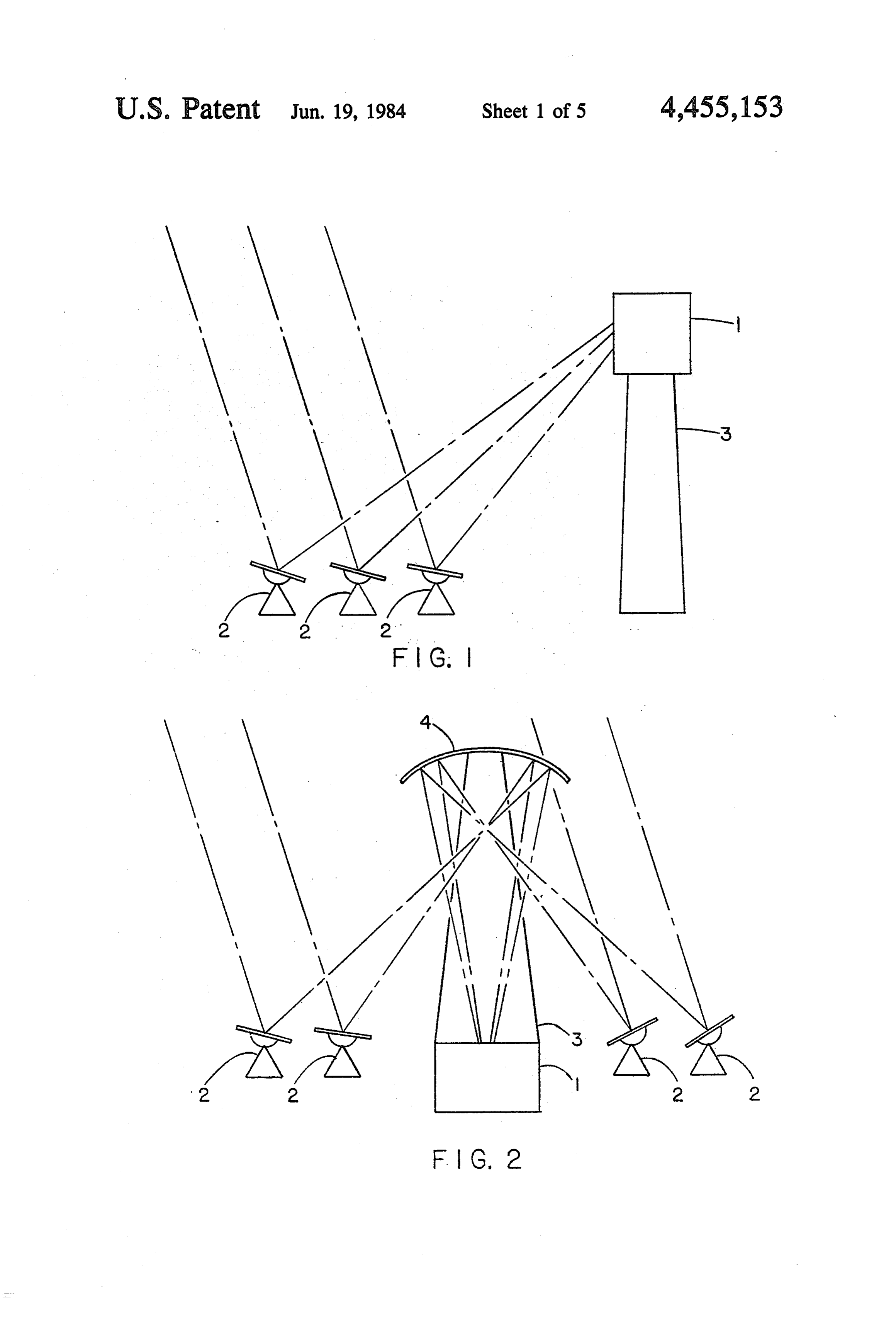
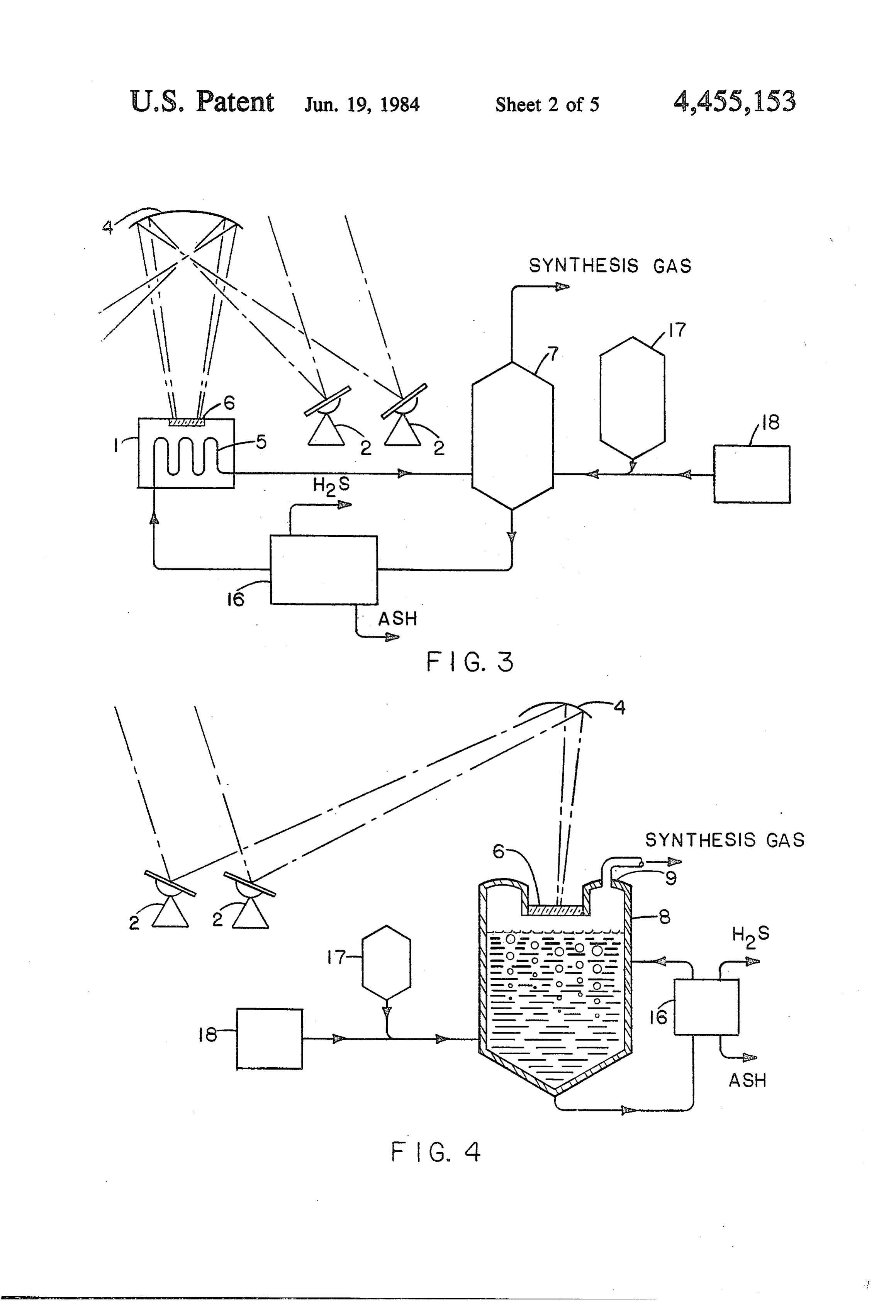
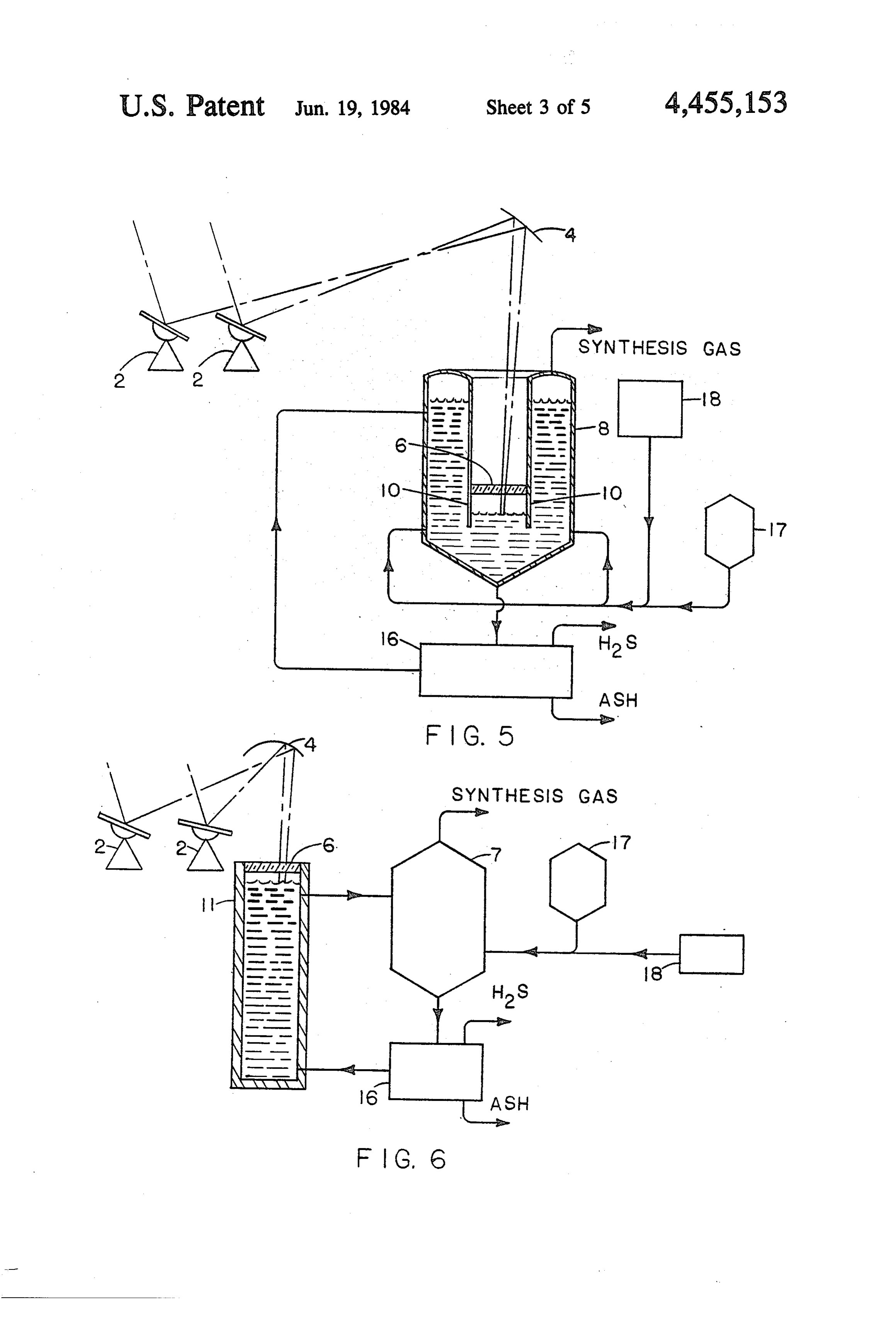
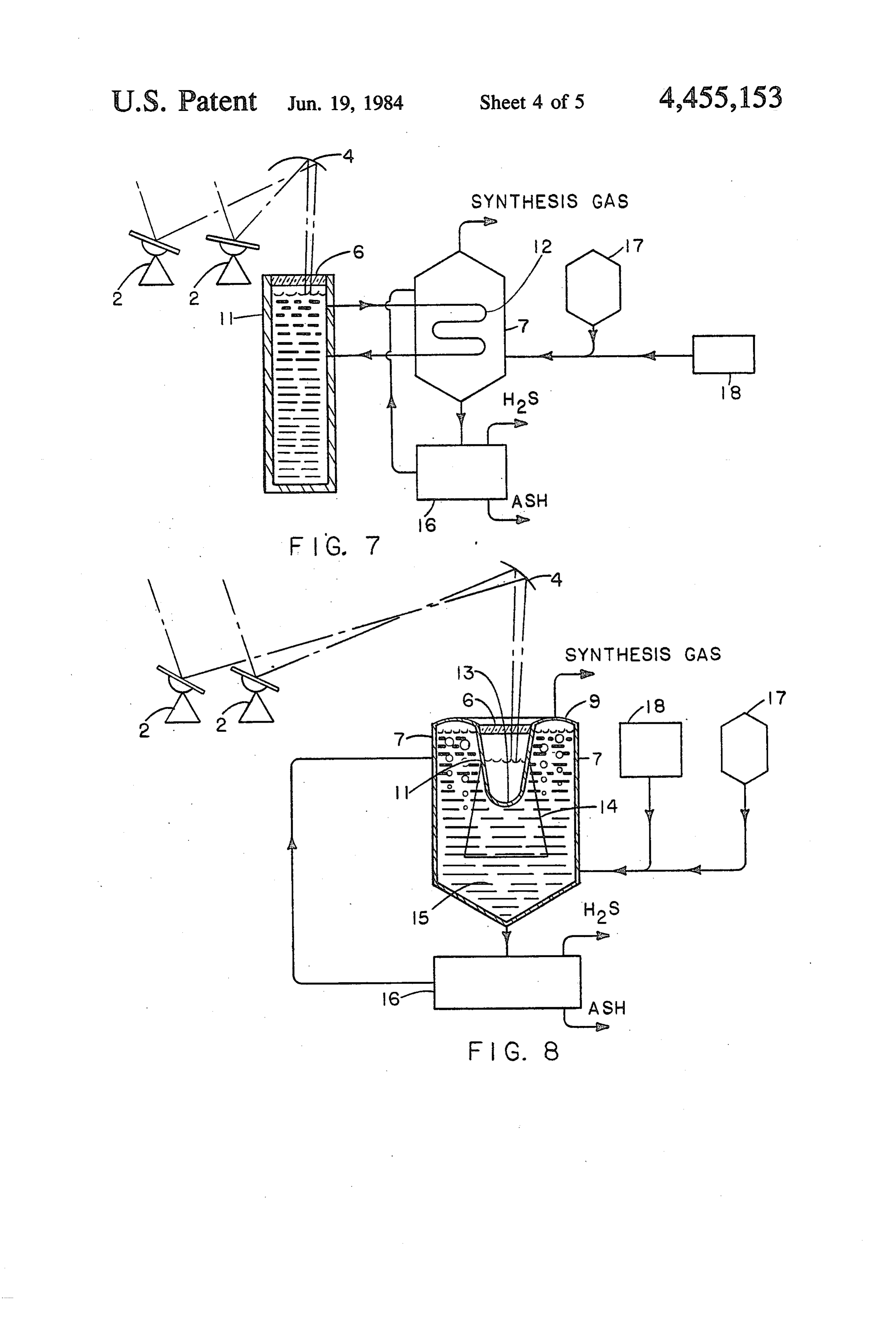
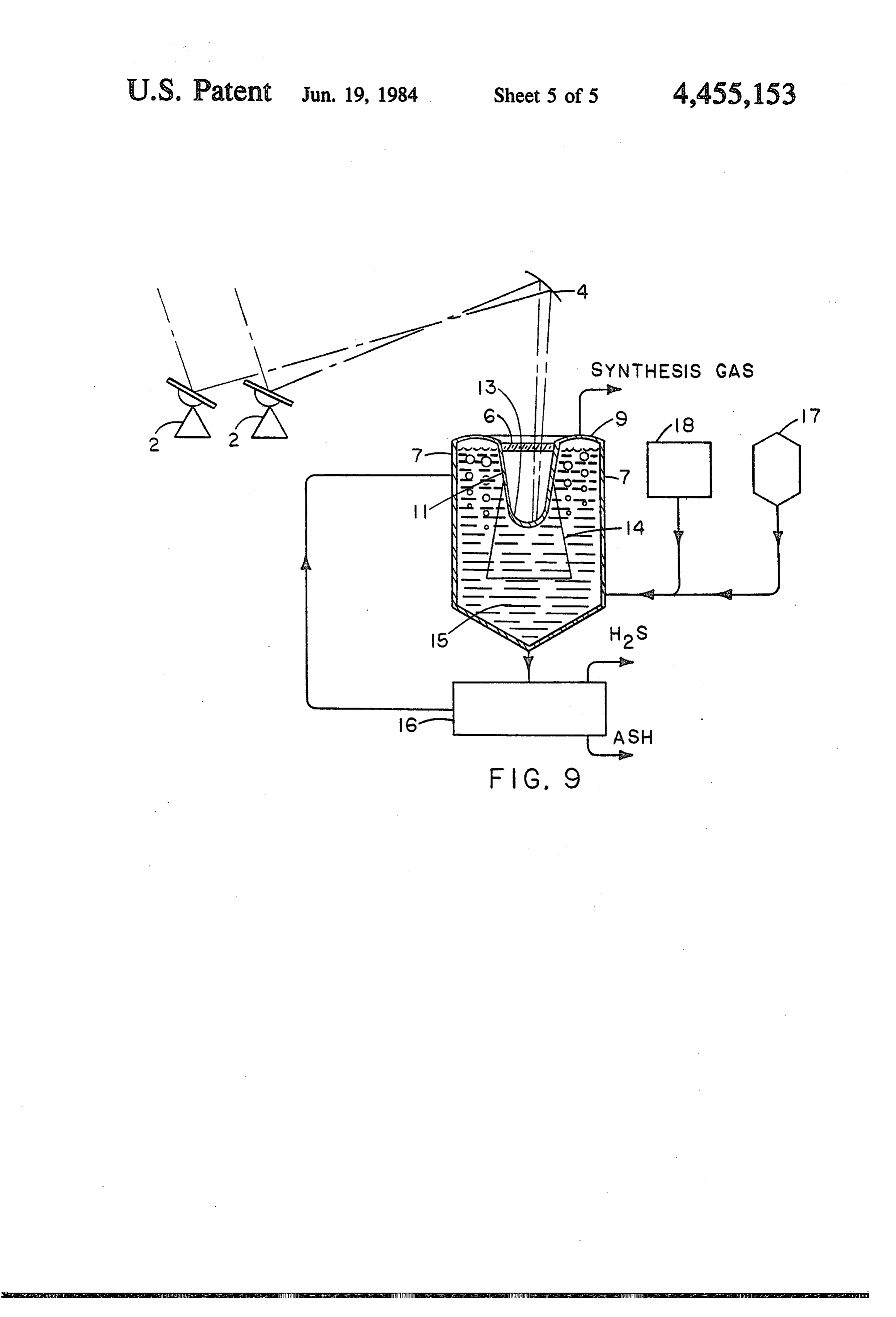
FIG. 1 is a schematic diagram of a prior art central gasification temperature, which will generally be in the receiver solar furnace; range of 700° C. to 1100 C.
Page 2drawing sheetscan →
Page 3drawing sheetscan →
Page 4drawing sheetscan →
Page 5drawing sheetscan →
Page 6drawing sheetscan →
Page 7scan →
heated by the concentrated solar radiation passing
APPARATUS FOR STORING SOLAR ENERGY IN through the imperforate window in the bottom of the SYNTHETICFUELS jacket, and thence through the perforated window in the bottom of the reactor, and impinging upon the
CROSS-REFERENCE TO RELATED 5 lower surface of the char.
APPLICATION The method and apparatus of Antal do not appear to This application a is continuation-in-part of U.S. pa be adapted to continuous processing of organic materi tent application Ser. No. 903,074, filed May 5, 1978 and als, since the catalyst of Antal is recovered by soaking now abandoned. the ash residue remaining after the gasification of the 10 organic material in water, and no means is shown in the
BACKGROUND OF THE INVENTION device illustrated in Antal for continuous removal of 1. Field of the Invention the ash residue.
Miy invention relates to processes and apparatus for Further, the fluidized bed reactor and surrounding storing solar energy in synthetic fuels, and more partic 15 jacket of the device of Antal must be insolated from ularly to processes and apparatus for thus storing solar below, rendering devices incorporating the teachings of energy which employ molten gasification media. Antal costly because high-strength support structures 2. Prior Art must be provided to elevate not only Antal's fluidized The use of solar heating to produce synthetic fuel, bed reactor and surrounding jacket, but also the associ thus storing solar energy in the synthetic fuel product, is ated feed stock hopper, air lock, and gas tight seals. In taught in U.S. Pat. No. 3,993,458, issued to Michael J. 20 addition, these high-strength support structures for Antal, Jr., on Nov. 23, 1976. elevating the major portions of the Antal device must More particularly, Antal teaches that a solar heat be constructed and arranged so that they do not sub fluidized reactant bed of char and organic material may stantially block the heliostat-directed solar radiation be used to produce synthesis gas by gasification reac from reaching the quartz window located at the bottom tions. According to Antal, the synthesis gas produced 25 Antal's reactor jacket.
by such gasification reactions can be used as a fuel, as a ofMoreover, the solid material handling means for chemical feedstock, or as a raw material in the produc charging organic tion of methanol. In the process of Antal, steam, carbon must comprise an material elevated into Antal's refuse hopper structure extending at one dioxide, or a mixture of these gases is used as the work end above the upper edge thereof, ing fluid, and is heated in a tower top solar furnace. This 30 time must not substanially block and the yet at the same solar radiation working fluid is used to fluidize the reactant bed of char directed by heliostats onto the quartz window at the and solid organic material.
In the single structural embodiment of Antal, quartz bottom of Antal's reactor jacket. Again, as with the support structure for his fluidized bed reactor, etc., windows are used to allow concentrated solar radiation to enter the bottom of a jacket surrounding the fluidized 35 solid material handling means suitable for supplying bed reactor and then to enter the bottom of the reactor. carbonaceous material to Antal's refuse hopper is no In this embodiment, the working fluid is introduced where shown or described, however broadly, in Antal. In addition, the gaseous gasification medium of Antal into the jacket near the top portion of the jacket. The working fluid then flows to the bottom of the jacket, is inherently inferior in solar radiation absorptivity to around the fluidized bed reactor. The bottom of Antal's 40 molten solid gasification media, and thus processes for jacket is supplied with a quartz window through which storing solar energy in synthetic fuels which employ concentrated solar rays pass. These concentrated solar molten solid gasification media will be characterized by rays are used to heat the working fluid of Antal to a higher efficiency of conversion of solar insolation into moderately high temperature, e.g., 700° C. to 1100 C. heat and will reduce capital equipment cost as com Antal's heated working fluid then enters the bottom of 45 pared with the method and apparatus of Antal. Antal's fluidized bed reactor through a second (perfo Further, the gaseous gasification medium of Antal rated) quartz window and is used in the reactor to fluid inherently possesses a much lower thermal conductivity ize the reactant bed of char and organic material. per unit volume than do molten solid gasification media, While the solar heated working fluid is thus entering and thus the efficiency of heat transfer to the carbona Antal's fluidized bed reactor from the bottom, the or 50 ceous material in devices embodying the invention of ganic material to be gasified is charged into the fluidized Antal will be less efficient than the corresponding heat bed reactor from the top through a feed hopper and transfer in devices employing molten solid gasification airlock system. media, and the gasification reactor vessel of Antal will In accordance with the teachings of Antal, a catalyst be considerably larger than optimum. The greater-than of cobalt molybdate or NzHCO3 is mixed with the or 55 optimum size of Antal's reactor will, of course, exacer ganic material to be gasified before it is charged to the bate the problems of elevatedly mounting Antal's reac fluidized bed reactor. The Organic material used in the tor, etc., discussed hereinabove.
process of Antal may, of course, be comminuted to a Yet further, the gaseous gasification medium of Antal degree dependent upon the economics of the system as must be passed through Antal's fluidized bed reactor at determined by those having ordinary skill in the art. high gas velocities in order to maintain the carbona In the device of Antal, the organic feed material is ceous material in the reactor in a fluidized state. pyrolyzed as it is heated by the working fluid. The It follows, then, that large amounts of steam and/or products of the resulting pyrolysis reactions in the fluid carbon dioxide are needed to maintain the carbonaceous ized bed reactor of Antal include synthesis gas, e.g., a material in Antal's reactor in the fluidized state. mixture of CO, H2, CH4, CO2, and H2O, ashes, tars, oils, 65 Since large amounts of steam and/or carbon dioxide liquors, and char. are needed to maintain the fluidized state in the reactor In the device of Antal, the solid char migrates to the of Antal, the amount of steam and/or CO2 in the raw lower section of the fluidized bed reactor where it is product synthesis gas produced by the reactor of Antal 8 will be much greater than the percentage of extraneous zine Chemical Engineering Progress, March, 1973, Vol gases in the synthesis gas product of a plant employing ume 69, No. 3. Of particular interest is the article in that a molten solid gasification medium. journal entitled Kellog's Coal Gasification Process, Additionally, Antal does not teach method or means commencing at page 31, and The COED Process Plus whereby to separate his raw synthesis gas from the Char Gasification, commencing at page 43. Reference carbonaceous material and char in the fluidized bolus or may also be had to the text New Energy Technology, by bed in his reactor. It appears evident from the teachings H. C. Hottel and J. B. Howard, 1971, The Massa of Antal, however, and the fact that large amounts of chusetts Institute of Technology. These technical publi Antal's gaseous gasification medium (steam and/or car cations like the above-cited U.S. patents, do not suggest bon dioxide) must be passed at high velocity through his 10 the great advantages to be derived from the employ fluidized bed, that a substantial portion of the carbona ment of solar energy as the heat sources in the described ceous material charged to Antal's reactor, and possibly processes, nor teach the processes and apparatus for a substantial portion of the char generated in Antal's achieving these great advantages which are uniquely reactor, will be emitted from Antal's reactor along with taught herein.
the raw synthesis gas product and ash emitted there 15 SUMMARY OF THE INVENTION from. This entrained carbonaceous material, and possi bly char, will have to be separated from the ash and It is accordingly an object of the present invention to synthesis gas and returned to Antal's fluidized bed reac provide greatly improved processes and apparatus for tor if a high rate of conversion of carbonaceous material storing solar energy in synthetic fuels. to synthesis gas is to be maintained in accordance with 20 It is a further object of my invention to provide con the teachings of Antal. However, neither method nor tinuous processes for storing solar energy in synthetic apparatus for thus separating carbonaceous material and fuels and apparatus for use in employing those pro char from the raw synthesis gas product of the reactor CeSSes.
of Antal is taught anywhere in Antal. It follows that It is a yet further object of my invention to reduce the even were one having ordinary skill in the art to supply 25 cost of apparatus for storing solar energy in synthetic such a separation process for use in connection with the fuels.
teachings of Antal, it might well be a costly process, It is an additional object of my invention to provide substantially affecting the overall economics of the apparatus for storing solar energy in synthetic fuels Antal process. which can be situated at ground level, rather than main Finally, it should also be recognized that the gaseous 30 tained in an elevated position by costly support struc gasification medium of Antal suffers from two addi tures.
tional deficiencies, viz., that the gasification medium It is another object of my invention to provide appa does not, as do certain molten solid gasification media, ratus for storing solar energy in synthetic fuels which serve as a catalyst for the gasification process taking may be insolated from above, rather than from below. place in the reactor, and that, unlike molten solid gasifi 35 It is yet another object of my invention to provide cation media, the solar-absorbing properties of Antal's processes and apparatus for storing solar energy in syn gaseous gasification medium cannot be enhanced by the thetic fuels in which the amount of carbon dioxide re addition thereto of suitable dopants. leased to the atmosphere is reduced. Also, the gaseous gasification medium of Antal is It is a further object of my invention to provide pro very poorly adapted, if adapted at all, to employment in cesses and apparatus for storing solar energy in syn a multi-stage solar gasification process in which a sepa thetic fuels in which the amount of coal, lignite, peat, or rate working fluid is heated by insolation, and this other carbonaceous material mined per unit energy of working fluid in turn heats the gasification medium. synthetic fuel is reduced, thus reducing damage to the Such a multi-stage process permits the selection of an ecostructure due to strip-mining or the like. optimum working fluid for direct insolation, i.e., a 45 It is a yet further object of my invention to provide working fluid having characteristics such as good solar processes and apparatus for storing solar energy in syn radiation absorptivity, chemical inertness, and stability thetic fuels which result in reduction of the overall heat at high temperatures. load into the atmosphere.
Processes and apparatus for the gasification of carbo Other objects of my invention will in part be obvious, naceous materials into synthesis gas using molten solid 50 and will in part appear hereinafter. gasification media are disclosed not only in prior U.S. My invention, accordingly, comprises the several patents but also in the technical literature. Among such steps and the relation of one or more of such steps with prior U.S. patents are U.S. Pat. Nos. 3,708,270; respect. to each of the others, and the apparatus em 3,567,412; 3,252,773; and 3,916,617. In these patents, a bodying features of construction, combinations of ele portion of the carbon in the carbonaceous material feed 55 ments, and arrangements of parts which are adapted to stock being gasified is reacted with a limited amount of effect such steps,all as exemplified in the following oxygen to provide the heat necessary to sustain the detailed disclosure, and the scope of my invention will endothermic gasification reaction in the gasification be indicated in the appended claims. reactor vessel. None of these patents makes any mention In accordance with a principal feature of my inven of the employment of solar radiation as an alternative to tion, a process for storing solar energy in synthetic fuel the reaction of oxygen with part of the carbon in the comprises introducing carbonaceous material and steam carbonaceous material to provide the necessary process into a molten gasification medium, supplying sufficient heat. A fortiori, none of these patents teaches solar solar heat to said gasification medium to maintain said energy as the heat source in their disclosed carbona gasification medium in the molten state and at a process ceous material gasification processes. Typical technical 65 ing temperature at which said carbonaceous material articles disclosing prior art molten solid gasification and steam react to produce gaseous product, and with medium processes for use in the gasification of carbona drawing said gaseous product as a product of the pro ceous materials into synthesis gas are found in the maga CeSS.
Page 9scan →
S 6
In accordance with another principal feature of my prises a central receiver i which is to be heated by invention, the solar heat supplied to said molten gasifi directly absorbing concentrated solar radiation. The cation medium in carrying out said process is supplied central receiver solar furnace of FIG. a further com to said molten gasification medium by directing concen prises a large plurality of tracking heliostats 2, each trated solar radiation thereupon. 5 adapted to concentrate solar radiation upon receiver . In accordance with yet another principal feature of As is well-known to those having ordinary skill in the my invention, the solar heat supplied to said gasification art, the tracking heliostats 2 serve to concentrate the medium in carrying out said process is supplied by solar radiation from a large area, viz., the total area of means of an intermediate working fluid, which working all of the heliostats 2 upon the small area of central fluid is selected for its high solar absorptivity. 10 receiver 1. In the well-known manner, the heliostats 2 In accordance with another principal feature of my are so disposed as to prevent each heliostat from inter invention, said gasification medium is impinged by solar fering with solar radiation travelling from any other radiation and contains a solar radiation absorption en heliostat to central receiver 1. In relatively flat terrain, hancing dopant. central receiver 1 will be situated at the top of a tower In accordance with yet another principal feature of 15 3 (FIG. 1) to prevent the blockage of solar radiation my invention, apparatus for storing solar energy in reflected by any heliostat 2 by any other heliostat 2. synthetic fuel comprises a reactor vessel containing a Tower 3 may, of course, in the well-known manner be molten gasification medium and said reactor vessel is eliminated where a natural terrain feature such as a hill provided with a window in its top surface through is available to serve in its place.
which window concentrated solar radiation is directed 20 Referring now to FIG. 2, there is shown a modified downwardly from a substantially horizontal reflector central receiver solar furnace which is particularly onto said gasification medium. adapted to carrying out the processes of my invention. In accordance with yet another principal feature of As seen in FIG. 2, receiver 1 is mounted at ground level my invention, said reactor vessel is provided with parti and the concentrated solar radiation from tracking he tition means defining with the portion of said reactor 25 liostats 2 is directed upon receiver 1 by means of a vessel lying above said gasification medium a first substantially horizontal parabolic reflector 4. This chamber having said window in its upper surface and a structural feature of my invention can be important in second chamber, said partition extending into said mol reducing capital plant expenditure, since some prior art ten gasification medium and defining below the surface central receiver solar furnaces employ receiver support thereofan opening into said first chamber, the means for 30 ing towers i,000 feet high, or higher. As will be evident transferring steam and carbonaceous material into said to those having ordinary skill in the art, informed by the reactor vessel passing into said second chamber at a present disclosure, reflector 4 will not be horizontally point above said opening into said first chamber, disposed in all embodiments of my invention. In some whereby said window is protected from said molten embodiments, central receiver 1 may be disposed at one gasification medium by a body of gaseous reaction 35 side of reflector 4, rather than directly below reflector product in the upper part of said first chamber. 4, and heliostats 2 may be sited to one side of reflector For a fuller understanding of the nature and objects 4, thus making it possible to dispose reflector 4 in a more of my invention reference should be had to the follow vertical position. In some embodiments of my invention ing detailed description, taken in connection with the the melting of the initially solid gasification medium accompanying drawings. may be carried out by means of the concentrated solar BRIEF DESCRIPTION OF THE DRAWINGS radiation reflected from heliostats 2, and the gasification medium may thus be melted and brought to a desired
FIG. 1 is a schematic diagram of a prior art central gasification temperature, which will generally be in the receiver solar furnace; range of 700° C. to 1100 C.
FIG. 2 is a schematic diagram of a solar furnace of the 45 Referring now to FIG. 3, it will be seen that the type used in principal embodiments of my invention; central receiver 1 of the first preferred embodiment of FIG. 3 is a schematic diagram of a first preferred my invention is supplied with concentrated solar radia embodiment of my invention, in which the solar energy tion by means of a plurality of tracking heliostats 2 and central receiver is at ground level below a tower a substantially horizontal parabolic reflector 4 disposed mounted reflector; 50 substantially directly above central receiver 1. FIG. 4 is a schematic diagram of a second preferred In many embodiments of my invention, including said embodiment of my invention; first preferred embodiment, the molten gasification me FIG. 5 is a schematic diagram of a third preferred dium will be a molten salt. It is to be understood, how embodiment of my invention; ever, that mixtures of molten salts may also be em FIG. 6 is a schematic diagram of a fourth preferred 55 ployed as the molten solid gasification medium in carry embodiment of my invention; ing out the processes of my invention. Thus, the term FIG. 7 is a schematic diagram of a fifth preferred "molten salt' as used hereinbelow also embraces mix embodiment of my invention; tures of molten salts.
FIG. 8 is a schematic diagram of a sixth preferred In accordance with the first embodiment of my in embodiment of my invention; and vention as illustrated in FIG. 3 the molten salt gasifica FIG. 9 is a schematic diagram of a seventh preferred tion medium is heated as it flows through tubes 5 con embodiment of my invention. tained in central receiver 1. Tubes 5, may, of course, be DESCRIPTION OF THE PREFERRED replaced by a single closed vessel or container having
Embodiments
suitable inlet and outlet means.
65 As also seen in FIG. 3, reflector 4 reflects concen
Referring now to FIG. , there is schematically trated solar rays to central receiver 1. The concentrated shown a central receiver solar furnace of well-known solar rays pass through a transparent window 6 in the type. The central receiver solar furnace of FIG. 1 com top of central receiver 1 and thereafter impinge upon 10 tubes 5. Transparent window 6 prevents heat loss from my invention, is separated into a heating zone and a central receiver 1. Tubes 5 in central receiver 1 are gasification zone. The heating of the molten salt in heat heated to a high temperature by the impingent solar ing and gasification vessel 8 of FIG. 5 will take place in radiation. Tubes 5 may be provided with solar radiation the lower section thereof. The lowermost portion, absorbing means such as fins or plates. A selective coat below transparent window 6, of the downwardly ex ing may be employed to increase the efficiency of solar tending cylindrical partition or vessel wall 10 of heating radiation absorption by maximizing the ratio of absorp and gasification vessel 3 shown in F.G. 5 serves to tivity of solar radiation to emissivity of thermal radia create a space between transparent window 6 and the tion from the solar radiation absorption surfaces. adjacent surface of the molten salt, which space may be The thus heated molten salt is conveyed by suitable O filled with an inert gas, thus helping to protect transpar piping arrangements to a gasification reactor vessel 7. ent window 6 from the hot and probably corrosive Alternatively, in accordance with my invention, a molten salt.
working fluid other than molten salt is heated in tubes 5, The principal advantage of the third preferred em which may be fabricated from refractory material, and bodiment of my invention occurs when, in accordance this alternative working fluid is passed by suitable pip 15 with the teachings of my invention, the carbonaceous ing to a heat exchanger, e.g., located in vessel 7, by material to be gasified is introduced into heating and which the solar heat is transferred from the alternative gasification vessel 8 well above the horizontal plane working fluid to the molten salt used in the gasification containing transparent window 6. When this is done, process. the gasification reactions will occur above the level of Referring now to FIG. 4, there is shown apparatus 20 the open lower end of partition 10, with the result that embodying the second preferred embodiment of my the synthesis gas in heating and gasification vessel 8 invention. In accordance with this embodiment, the does not come into contact with transparent window 6. molten salt is heated by solar radiation reflected from This feature of my invention is of particular importance reflector 4, which passes through a transparent window when one or more of the gases formed during the gasifi 6 to be directly absorbed by the molten salt in a combi 25 cation reactions in heating and gasification vessel 8 are nation heating and gasification vessel 8, the structure of such as to corrode or optically degrade the transparent which constitutes a principal feature of my invention. window 6.
As seen in FIG. 4, the uppermost portion 9 of heating Referring now to FIG. 6, there is shown the fourth and gasification vessel 8 includes an annular raised por preferred embodiment of my invention. In this embodi tion or dome. Annular dome 9 may be seen to be pro 30 ment of my invention, as in the two previously de vided with an outflow pipe whereby the synthesis gas scribed embodiments, the concentrated solar rays from product of the process of my invention is collected and reflector 4 pass through a transparent window 6 and removed. thereafter impinge upon the molten salt gasification As also seen in FIG. 4, transparent window 6 is lo medium. The primary difference bewteen this fourth cated in the center of the uppermost portion 9 of heating 35 preferred embodiment of my invention and the two just and gasification vessel 8. Transparent window 6 com previously described embodiments of my invention pletely fills the inner opening of annular dome 9 and is consists in the employment of separate heating and sealed to the lower end of the cylindrical wall which gasification vessels. The heating vessel is designated by defines the inner face of annular dome 9. The level of the reference numeral 1. The gasification vessel, desig the molten salt in heating and gasification vessel 8 is so 40 nated by the reference numeral 7, may be substantially maintained that transparent window 6 is not contacted identical to the gasification vessel 7 of the first preferred by the hot and probably corrosive molten salt. Thus, embodiment.
transparent window 6 is located below the point of In the apparatus of the fourth preferred embodiment removal of the synthesis gas in annular dome 9. the molten salt is heated in vessel 11 by absorbing the Thus, the structural features of the heating and gasifi 45 concentrated solar rays coming through transparent cation vessel of my invention, as just described, make window 6 of heating vessel 11. After thus being heated, possible the elimination of the pipes, pumps, and valves the molten salt is pumped into gasification vessel 7. The needed to transport the molten salt from receiver a to principal advantage of this fourth preferred embodi gasification reactor vessel 7, etc., in the abovedescribed ment, like the first preferred embodiment, lies in the fact first embodiment of my invention. 50 that gases formed during the gasification processes, In accordance with a further feature of my invention, which might chemically attack or optically degrade additives or dopants may be added to the molten salt in transparent window 6, do not come into contact with heating and gasification vessel 8 of the second preferred transparent window 6. In order to protect transparent embodiment of my invention, or selective solar absorp window 6 in this preferred embodiment, a space be tion surfaces may be provided, in order to increase the 55 tween transparent window 6 and the surface of the rate of solar absorption and thus to more efficiently heat molten salt bath A4 may be provided, and the same filled the contents of heating and gasification vessel 8 of this with an inert gas or vacuum for thermal insulation and embodiment. Suitable additive or dopant materials are to protect window 6 from hot corrosive molten salt. As described, for example, in an article by William D. in the previously described second and third preferred Drotning entitled Optical Properties of Solar-Absorb 60 embodiments, additives or dopants may be used to in ing Oxide Particles Suspended In A Molten Salt Heat crease the rate of solar radiation absorption into molten Transfer Fluid, found at Volume 20, pages 313 through salt bath 14 thereby increasing the efficiency of the 319, of Solar Energy, Pergamon Press, 1978. system of this embodiment.
Referring now to FIG. 5 there is shown a third pre Referring now to FIG. 7, there is shown a fifth pre ferred embodiment of my invention. In this embodiment 65 ferred embodiment of my invention. In accordance the combined heating and gasification vessel of my with this fifth preferred embodiment of my invention, a invention, designated by the reference numeral 8 in working fluid other than molten salt is employed to connection with the second preferred embodiment of absorb the concentrated solar radiation provided by 11 tracking heliostats 2, reflector 4, etc. In accordance scribed preferred embodiment, fins 15 can be used to with this embodiment, the molten salt gasification me increase the rate of heat conduction from heating vessel dium is heated by means of a heat exchanger 12, which 11 into molten salt bath 14, and, with the selected sur serves to transfer heat from the solar heated working face material and the configuration of well 13, achieve fluid to the molten salt gasification medium. This fifth ment of operating temperatures at start-up time can be preferred embodiment of my invention permits the se insured in the least amount of time as well as a maximum lection of a working fluid having desirable properties, amount of time at operating temperatures over a greater such as stability under the strong heating by the concen range of sky conditions.
trated solar radiation, good solar radiation absorption It should be noted that in FIGS. 3 and 9, if suitably characteristics, and chemical inertness, i.e., low or no O selected solar radiation absorptive material is applied to corrosiveness, with respect to heating vessel 11 and the solar radiation impinged surfaces, and in FIGS. 6, 7, transparent window 6. This working fluid may, of and 8, if a suitably selected working fluid is used, it may course, be a single substance or a mixture of different be possible to dispense with transparent window 6. As materials. previously noted, however, transparent window 6 can Referring now to FIG. 8, there is shown a sixth pre 15 provide major advantages, such as significantly reduc ferred embodiment of my invention. In accordance ing heat losses by allowing the creation of a vacuum with this embodiment of my invention, the gasification vessel 7 surrounds the heating vessel 11. Heating vessel between the solar radiation impinged surface and trans parent window 6. Window 6 will reduce heat losses 11 defines a well 13 which extends deeply into the mol ten salt bath 14. Heating vessel 11 itself may be formed 20 through also serve radiation, conduction, or convection, and will to prevent the solar radiation impinged sur from suitable metallic or refractory material, e.g., a face or surfaces suitable ceramic or ceramet, and is gastightly joined to atmosphere, whichfrom will coming into contact with the in turn prevent the solar radia the remaining wall portion of heating vessel 11 As seen tion impinged surface, whether the surface of a solid or in FIG. 8, well 3 is closed by a transparent window 6. the surface of a fluid, from reacting In the operation of the apparatus of the sixth pre 25 atmosphere, especially the oxygenwith in the gases in the the atmosphere.
ferred embodiment of my invention, concentrated solar Reduction in heat loss may be achieved by interposition radiation reflected by reflector 4 passes through trans parent window 6 and impinges upon a suitable working of transparent window 6 without the creation of a vac uum therebehind, but the reduction in heat loss without fluid in heating vessel 11, i.e., contained in well 13. The the vacuum will be less.
working fluid in well 13 may be provided with a suit 30 able additive or dopant, thereby increasing the rate of a downwardthe abovedescribed embodiments of my invention solar radiation absorption by the solar-energy-to-heat onto the ground-surface-mounted central conversion system of this embodiment. This absorption receiver 1. As noted hereinabove, the employment of of solar radiation will raise the fluid in well 13 to high downwardly-directed reflector 4, which is a character temperature. The high temperature of the working fluid 35 istic feature of my invention, provides great advantage in well 13 will cause heat to be conducted from the by way of increasing the focal length of the solar ray working fluid through the walls of heating vessel 11, concentration system, and allowing central receiver 1 which projects into molten salt bath 14. Heating vessel to be built on the ground in flat terrain. In addition to 11 may be provided with fins 15, projecting into molten the cost-savings attendant upon the building of central salt bath 14 whereby to increase the rate of heat conduc receiver 1 on the surface of the earth, rather than on an tion from heating vessel 11 into molten salt bath 14. A elevated tower, other advantages are attained by mak vacuum or inert gas filled space may be provided to ing use of the downwardly directed reflector 4 of my separate the working fluid in heating vessel 11 from invention. In some embodiments of my invention, the transparent window 6, thereby tending to reduce the use of downwardly-directed reflector 4 helps to protect heat losses from heating vessel 11 and also helping to 45 transparent window 6 by making it impossible to locate protect transparent window 6 from the hot and possibly transparent window 6 at the top of the central receiver, corrosive working fluid therein. gasification vessel, or heating and gasification vessel, Referring now to FIG. 9, there is shown a seventh rather than at the bottom thereof, since the top-located preferred embodiment of my invention, which is sub transparent window 6 of my invention can be separated stantially similar to the sixth preferred embodiment 50 from the working fluid or gasification medium, and at with the exception that no working fluid is contained in the same time the transparent window can be non-load heating vessel 11. In accordance with the seventh pre bearing, not having to support the weight of the work ferred embodiment, then, heating vessel 11 serves as a ing fluid or gasification medium in the central receiver, heating zone for gasification vessel 7. In the seventh gasification vessel, or heating and gasification vessel. preferred embodiment the concentrated solar radiation 55 The processes and apparatus for heating the molten reflected by reflector 4 impinges directly upon a wall salt described hereinabove can be used to store solar area of heating vessel 11 after passing through transpar energy and make it available during periods of cloudi ent window 6. This wall area of heating vessel 11 is ness or at night for purposes other than the gasification raised to high temperature by absorption of the impin of carbonaceous material. For instance, the gaseous gent concentrated solar radiation, and thus conducts medium heating means of one of the embodiments of heat into molten salt bath 14. It is to be noted that the my invention described hereinabove may be used to configuration of well 13 provides increased surface area store solar energy for the purpose of generating elec exposed to molten salt bath 14, which in turn increases tricity thermoelectrically. In this application of my the rate of heat conduction into molten salt bath 14. A invention, the molten salt or other working fluid could properly selected surface material may be used to maxi 65 be heated during periods of sunshine, and the solar mize the ratio of absorptivity of solar radiation to emis energy stored in the molten salt or other working fluid sivity of thermal radiation of the inner solar radiation utilized later as dictated by the then current demand for absorption surface of well 3. As in the previously de electricity.
Page 12scan →
As will be evident to those having ordinary skill in due to these high temperatures, the high heat capacity the art, informed by the present disclosure, it is pre of the molten salt, the good heat conductivity of the ferred that the fluid in the heating vessel be a liquid, molten salt, and the even temperature distribution of the rather than a gas, since liquids in general have much molten salt bath 14 will curtail the formation of tars, oils higher solar absorptivity per unit volume than gases, and liquors during the pyrolysis reactions. Any tars, oils and also much higher thermal conductivity per unit and liquors formed during the pyrolysis reactions will volume and much higher thermal capacity per unit be induced to crack into more CO, H2, CH4, CO2 and volume. steam by the strong catalytic action of the molten Na2 In carrying out the processes of my invention, mak CO3 and the readily available heat from the molten ing use of the molten gasification medium heating 10 Na2CO3 bath 14. Experiments done with coal as the means of one of the several abovedescribed embodi carbonaceous matter have shown that the coal will ments of apparatus of my invention, the steps of charg gasify completely to a synthesis gas with no tars, oils or ing carbonaceous material to the molten gasification liquors in the product synthesis gas when molten Na2 medium, extracting synthesis gas, disposing of waste and byproducts, etc., may be substantially like the cor 15 CO3
The is used to gasify the coal.
char will, under the strong heating and catalytic responding steps of known molten gaseous medium gasification processes, as taught, e.g., in U.S. Pat. Nos. actions of the molten Na2CO3, and the presence of steam in the gasification reactor vessel 7, react with the 3,708,270; 3,567,412; 3,252,773; and 3,916,617. steam in accordance with the known carbon-steam re Typical post-heating processing steps which may be action to form more H2 and CO (Equation 1, infra). The followed in carrying out one of the processes of my invention using one of the apparatus embodiments of major reactions in the gasification of solid or liquid carbonaceous matter besides the pyrolysis reactions my invention described hereinabove may be generally described as follows, thus putting the subject matter which occur in reactor vessel 7 are: thereof within the scope of one having ordinary skill in Equation 1. C+H2O-CO-i-H2 (carbon-Steam the art as informed by the present disclosure. 25 reaction)
In this description it will be assumed that the molten Equation 2. CO--H2O-H2--CO2 (water gas gasification medium is molten Na2CO3, which has been reaction) proven to be a very effective molten salt for use in Equation 3. C-CO2-2CO (carbon-Carbon dioxide reaction.)
carbonaceous material gasification processes. It is to be Equation 4. C-2H2-)-CH4 carbon-H2 reaction) understood, however, that other molten salts or various 30 Equation 5.3H2--CO-CH4-i-H2O (formation of mixtures of molten salts may be employed in carrying CH4 in reactor) out the processes of my invention. Equation 6.2H2+2CO-CH4+ CO2 (formation of CH4 in reactor)
This molten salt, Na2CO3, will either be heated in a Equation 7.
gasification vessel 7 or in a separate heating vessel 11 as Na2CO3--H2O-NaOH-CO2(hydrolysis of described hereinabove. If heated outside the gasification 35 N2CO3 in reactor) vessel, the molten gasification medium will be pumped Some of the CO2 formed by the pyrolysis reactions to gasification vessel 7 as described hereinabove. Hot and the hydrolysis of Na2CO3 (Equation 7) will react steam and a solid carbonaceous material will then be with the char to form more CO (Equation 3). If desired, introduced into the bottom section of reactor vessel 7. CO2 may be added to reactor vessel 7 with the hot The carbonaceous material feedstock may be shredded, steam to promote Equation 3 and depress Equation 7. If ground, crushed, milled, or otherwise comminuted, in suitable catalysts are found, it may be desirable to re the judgment of one having ordinary skill in the art, place the steam with CO2 to react with the char to form bearing in mind the economics of the system. The hot more CO in accordance with Equation 3. The probabili steam may be provided by solar heating, by the use of ties of this happening appear to be small. heat exchangers to obtain heat from the product synthe 45 Some of the H2 formed during the pyrolysis reactions sis gas as it leaves gasification reactor vessel 7 and/or by will react with the char to form CH4 (Equation 4). At the use of heat exchangers to obtain heat from the mol this time it is believed that the carbon-steam reaction ten salt as it leaves the gasification reactor vessel 7. The (Equation 1) is the primary reaction in the gasification hot steam can be used to carry the particles of carbona process, and that the carbon-CO2 reaction (Equation 3) ceous material into reactor vessel 7, and also to remove 50 and the carbon-H2 reaction (Equation 4) are secondary the air from the stream of carbonaceous material. reactions in the molten salt gasification process. The Turbulence may be induced in reactor vessel 7 in water gas reaction (Equation 2) alters the proportion of order to increase the gasification rate. The movement of CO, H2, CO2 and steam in the raw synthesis gas prod gases and liquids in reactor vessel 7 and/or mechanical lict.
agitators may be used to create turbulence in reactor 55 The proportion of CH4 in the synthesis gas can be vessel 7. increased if desired by altering conditions in reactor 7 to As the steam and carbonaceous material moves up favor Equations 4, 5 and/or 6. A side reaction which is through molten salt bath 14 in reactor vessel 7, the generally considered to be undesirable is the hydrolysis strong heating action of the molten Na2CO3, the cata of the molten Na2CO3 to form NaOh and CO2 (Equa lytic action of the molten Na2CO3, and the turbulence tion 7). This reaction will increase the proportion of in molten Na2CO3 bath 14 will cause the carbonaceous CO2 in the raw synthesis gas and increase the amount of material to pyrolyze at a rapid rate. As a result, the Na2CO3which must be made up. The use of K2CO3 will carbonaceous material will break down into synthesis alleviate this problem as K2CO3 will hydrolyze to a gas consisting of CO, H2, CH4, CO2, and steam, carbon lesser degree than Na2CO3 under the same gasification in the form of char, ash, and sulfur in the form of sulfide 65 conditions. However, K2CO3 is more expensive than OS Na2CO3.
The high temperatures used for the gasification reac All the gases formed during the gasfication of the tions, the rapid heating of the carbonaceous material carbonaceous material in reactor vessel 7 will collect at 13 the top of reactor vessel 7. These gases, which make up can use solar energy as the heat source for the molten the raw synthesis gas, will be removed from the top of salt gasification processes of my invention. reactor vessel 7 and sent to the clean-up and purification Alternative processes and apparatus for practicing section where any impurities in the synthesis gas will be the solar molten salt gasification processes of my inven removed. The synthesis gas can then be enriched by tion are described below.
removal of the CO2 and H2O. The synthesis gas will The first alternative is to use K2CO3, LiCO3 or any then be used as a fuel or used as a raw material in the one of the many possible eutectics formed by mixing production of other synthetic fuels or chemicals. Reac together alkalai metal carbonates in place of Na2CO3 as tions which can be used to utilize the synthesis gas after 10 the molten salt in the above-described gasification pro it leaves the reactor are: cesses of my invention.
The second alternative is to employ a separate vessel
Equation 2. CO-H2O-H2--CO2 (water gas to clarify by settling the ash in the used molten salt. This reaction)
Equation 5.3H2--2CO-)-CH4--H2O (synthesis of will allow use of vigorous turbulence in the reactor methane) vessel to enhance gasification rates, and good quiescent Equation 6.2H2--2CO-CH4--CO2(synthesis of 15 settling conditions in a separate clarification vessel. methane) The third alternative is to eliminate or substantially Equation 8. CO-2H-CH3OH (synthesis of reduce the amount of steam introduced into reactor 7. methanol) This will substantially reduce the carbon-steam reaction Equation 9. N2+3H2-2NH3 (synthesis of ammonia)
Suitable catalysts known to those having ordinary 20 (Equation 3) and result in carbon in the form of char skill in the art will be used in the synthesis of methane, being removed from the reactor. This char will float on the molten salt and, when separated from the molten methanol and ammonia.
The water gas reaction (Equation 2) can be used to salt,Thewillfourth be a valuable by-product. alternative is to clean only a portion or alter the proportion of H2 and CO in the synthesis gas none of the used molten salt instead of purifying the after removal from gasification vessel 7. This reaction 25 entire amount of used molten salt being removed from can be used to obtain nearly pure hydrogen by making reactor vessel 7. The unpurified molten salt will either Equation 3 go to the right to the extent that is economi be recycled back to reactor vessel 7, resulting in an cally and technically feasible. increase in the concentration of ash in the molten salt After alteration to proper proportions, the synthesis bath in vessel 7, or disposed of without purification. Use gas can be converted to methane by use of Equations 5 30 of an inexpensive salt and high allowable concentrations or 6 or methanol by means of Equation 8 or ammonia by of ash in the molten salt bath during the gasification a means of Equation 9. There will be some methane in process will favor this modification.
the synthesis gas as it leaves the reactor, which will The fifth alternative is to directly separate the ash facilitate the production of methane from the synthesis from the molten salt without going through the purifi gas. As mentioned previously, The proportion of meth 35 cation procedure outlined above. A portion or all of the ane in the raw synthesis gas can be increased by manipu used molten salt will be sent to an ash removal section lating the conditions in gasification reactor vessel 7. A adapted for filtering the ash from the molten salt or synthetic gasoline can be produced from methanol using centrifugation to separate the ash from the molten using a process recently developed by Mobil Oil Com salt. This alternative will be enhanced if only a small pany. portion of the ash will dissolve in the molten salt. During the gasification reactions, ash and sulfur from The sixth alternative will be used with the fifth alter the carbonaceous material will be incorporated into native and will remove the sulfur in the molten salt molten Na2CO3 bath 14. The sulfur is converted into which is not removed by direct filtration or centrifuga sulfide ions and becomes part of molten salt bath 14. A 45 tion. The concentration of the sulfide ion in the reactor portion of the sulfur will be dissolved in the ash and the vessel may be allowed to increase until the sulfur forms rest will be present as a solid or liquid contaminant of hydrogen sulfide gas. The reaction is: molten salt bath 14. A portion of the ash must be contin Equation 12. Na2S--CO2-H2O-Na2CO3 + H2S. uously or periodically removed from molten salt bath The hydrogen sulfide will mix with the raw synthesis 14 to keep the concentration of ash in molten salt bath 50 gas in reactor vessel 7 along with the raw synthesis gas, 14 within allowable limits for good gasification rates. The hydrogen sulfide will then be removed from the At the bottom section of reactor vessel 7 there will be a settling zone. The ash will settle toward this settling synthesis gas using conventional procedures. This mod Zone, resulting in molten Na2CO3 bath 14 having a dure which doesusenotofremove ification allows a molten salt purification proce the sulfur in the form of higher concentration of ash in this settling zone. 55 the sulfide ion from the used molten salt, such as the The molten Na2CO3 at the bottom of the settling zone direct filtration or centrifugation purification method will be siphoned off from the settling zone and sent to mentioned above.
the impurities removal section 16. Here the ash and It will be noted that in FIGS. 3 through 9 the carbo sulfide ions will be removed from the molten Na2CO3. naceous material is fed from the carbonaceous material A process for removing impurities from salts such as lock hopper 17 into reactor vessel 7 or gasification and Na2CO3 which is being used in the conventional molten heating vessel 8 (FIGS. 4 and 5) by means of steam from salt gasification process is described in U.S. Pat. Nos. a steam generator 18.
3,710,737 and 3,708,270. It will thus be seen that the objects set forth above, The processes and apparatus described above do not among those made apparent from the preceding de encompass all the processes and apparatus for practic 65 scription, are efficiently attained, and since certain ing the solar molten salt gasification processes of my changes may be made in the above processes and appa invention. Thus, this description is not intended to en ratus without departing from the scope of my invention, compass all the possible processes and apparatus which it is intended that all matter contained in the above 14 description or shown in the accompanying drawings shall be interpreted as illustrative only, and not" in a limiting sense.
It is also to be understood that the following claims are intended to cover all of the generic and specific features of my invention hereindescribed, and all state ments of the scope of my invention which, as a matter of language, might be said to fall therebetween.
1. Apparatus for storing solar energy in synthetic fuel, comprising:
a reactor vessel having a solar radiation pervious window in its upper surface and containing a gasifi directing means for directing solar radiation through said window and onto said gasification medium to raise the temperature of said gasification medium to a temperature at which carbonaceous material and 20 steam react to produce gaseous product;
a supply vessel containing carbonaceous material; a steam generator;
means for transferring steam and carbonaceous mate rial from said steam generator and said supply ves 25 sel into the gasification medium in said reactor vessel;
purifying means for removing byproducts of the reac tion of said steam and said carbonaceous material from said gasification medium;
means for transferring gasification medium from said reactor vessel to said purifying means;
means for transferring purified gasification medium from said purifying means to said reactor vessel; and means for withdrawing gaseous product from said reactor vessel;
said reactor vessel being provided with partition means depending from the upper portion of the reactor vessel and surrounding said window, said partition means defining with the portion of said reactor vessel lying above said gasification medium an annular chamber defining with said window a central chamber, said partition means extending into said gasification medium and defining below the surface thereof an opening into said central chamber, and said means for transferring steam and carbonaceous material into said reactor vessel pass ing into said annular chamber at a point above said opening into said central chamber, whereby said window is protected from said molten gasification medium by a body of gaseous reaction product in the upper part of said central chamber.
Provenance
- Collection
- Patents citing this work
- Pages
- 14
- Method
- pdftotext (the PDF's own text layer) + pdftoppm 300dpi page scans
- Patent office record
- patents.google.com →
- Source
- Google Patents citing-documents table
- Assignee
- Jakahi Douglas Y
- Published
- 1984-06-19
- Transcribed from
- patentimages.storage.googleapis.com →