

patent · US4470405A
Method and apparatus for controlling insolation in a building
11 September 1984
Text
Page 1bibliographic recordscan →
United States Patent (19)
Landstrom et al.
54 METHOD AND APPARATUS FOR
CONTROLLING INSOLATION IN A
BUILDING
75 Inventors: D. Karl Landstrom; Sherwood G.
Talbert, both of Columbus; William
H. Wilkinson, Upper Arlington;
George H. Stickford, Jr.; Frank E.
Jakob, both of Columbus, all of Ohio Assignee: Battelle Memorial Institute,
Columbus, Ohio
51 Int. Cl.................................................. F24J 3/02 52 U.S. C. .................................... 126/428; 126/445;
2,439,553 4/1948 Winn ............................... 26/900X 3,107,052 10/1963 Garrison ......................... 126/428 X
3,475,868 11/1969 Johnson .............................. 47/17 X 4,108,373 8/1978 Chiapale et al. ... 126/428 X 4,111,186 9/1978 Ross et al. ........................... 126/426 4,127,102 11/1978 Berman ............................... 126/444 4,147,002 4/1979 Kautz .................................. 47/17 X 4,210,128 7/1980 Mattson ..... ... 126/444 4,278,075 7/1981 Heierli................................. 126/445 4,338,919 7/1982 Hwang ............................ 126/900 X
FOREIGN PATENT DOCUMENTS
Primary Examiner-Larry Jones
Attorney, Agent, or Firm-Robert B. Watkins
A method, apparatus and system is provided for con trolling the rate of insolation transmission through the roof of a building, such as a greenhouse. The roof is provided with translucent panels through which liquid containing opaquing material passes. Control is effected by varying the amount of opaquing material passing through the panels, according to preselected optimum fulfillment of the combined heating, cooling and insola tion needs of the building under varying atmospheric conditions.
5 Claims, 6 Drawing Figures
Drawings
Page 2drawing sheetscan →
Page 3drawing sheetscan →
Page 4scan →
plurality of laterally spaced longitudinal passageways.
METHOD AND APPARATUS FOR CONTROLLING The main body of passageways is disposed between an NSOLATION IN A BUILDING upper glazing member and a lower support member. Combining solar heating apparatus with insolation
SUMMARY OF THE INVENTION 5 controlling apparatus, has not received as much atten This invention relates to a method and apparatus for tion in the prior art as has been given separately to these controlling the amount of insolation entering a building. concepts.
More particularly it relates to a method and apparatus U.S. Pat. No. 4,108,373-Chiapale et al, discloses a in which the amount of solar radiation passing through 10 greenhouse wherein a liquid is passed through the roof the roof of a building is controlled by varying the and walls. The liquid has infrared filtering characteris amount of opaquing material present in a plurality of tics such as provided by a copper chloride in water panels in the roof of the building. solution. The solution is passed through the walls as a In summary, the method of this invention includes; heat absorbing medium.
(a) conveying a liquid containing an opaquing material Attention is given to restricting light transmission through a plurality of translucent conduits in the roof of 15 into greenhouses; i.e. shading, in U.S. Pat. No. a building, (b) controlling the rate of insolation passage 4,147,002-Kaatz, in which a dry particulate material is through the conduits and the heat absorption of the blown into roof and wall cavities when shading is de liquid by varying the number and combinations of con sired, and drawn out of the cavities when unrestricted duits conveying the liquid through the roof, and (c) light transmission is desired. The process of the patent is simultaneously or alternatively varying the amount of 20 to blow the particulate material into place and then to opaquing material in the liquid being conveyed through subsequently reverse the process later and withdraw the the conduit. . material.
The apparatus of this invention comprises: a roof It is known that there are a large variety of atmo structure including frame assemblies of translucent inso lation passing material, constructed into separate panels 25 spheric or weather conditions which occur as fre quently as every day, and as infrequently as once a with contiguous integrally formed first conduits in liq season, that influence the insolation and heating condi uid fluid communication with common header second conduits at opposite ends; including a source of a liquid tions parts to which a greenhouse is subjected. In certain of the world, high temperatures and insolation is containing opaquing material selected to enhance the encountered insolation blocking opacity properties of the liquid; prevalent at innight.
30 the daytime while low temperatures are further including means constituting a system for con grees of shading areInrequiredsuch circumstances, various de necting and conveying, the liquid from the source required to be added at night.in Inthesome daytime and heat is circumstances, through the second and first conduits; and means for cooling is required when the amount of insolation re controlling the rate of insolation transmitted through the panel by varying the amount of opaquing material 35 quires that shading be added.
passing through the panels according to a preselected growing cycle toof plant
In addition these requirements for the optimum life in the greenhouse, it is desir optimum fulfillment of the combined heating, cooling able that maximum energy efficiency be obtained in and insolation needs of the building.
Greenhouses are a kind of building which require that heating and cooling the greenhouse. Therefore, an addi significant amounts of solar radiation; i.e. insolation, be 40 tional parameter that should be controlled is the amount of heat absorption obtainable from the solar radiation admitted to the inside. Traditionally, greenhouses have that is available.
been constructed with roofs that are either made of In order to meet the varying requirements for insola transparent/translucent material, or roofs that are adapted to be removed in one way or another such as tion and heat absorption, this invention provides, a sliding panels, furling canvas, etc. '' .. . 45 means of varying the amount of opaqueness or opacity The growing plants in greenhouses require different in a plurality of roof panels of a building. The opacity amounts of insolation and different cycles depending on may be varied and controlled in either of one or two their variety and their period in the growing cycle. ways, or by a combination of the two. Since greenhouses and other buildings are located in The term opacity, as used herein, means the capacity various climates, the amount and intensity of available 50 of a material to block and absorb or reflect light. The insolation is different depending on the locality. terms translucent and transparent relate to the capacity For the above reasons, it is important that a simple of a material to transmit light. Transparency is a higher and efficient method and apparatus be provided to vary degree of translucence whereby the light is transmitted and control the amount of insolation that reaches the with less diffusion so that matters of form are more inside of the building. 55 apparent when viewed from the opposite side. In recent years, increasing costs of energy has fo Recent advances in the art of solar heat absorption cused important attention on the use of solar energy as techniques have brought about a variety of "black liq a source. Solar radiation is most frequently used in the uid” materials that are especially compounded or for form of heat from the sun's rays which are absorbed in mulated to enhance various properties desired in solar other materials subjected to the solar radiation. A com 60 heat absorption usage. Frequently used black liquids are mon approach is the use of solar panels in which the now compounded with carbon black particles in submi rays of the sun are absorbed and conducted to a liquid cron sizes in which the particles remain in colloidal circulating in conduits on the roof of buildings and suspension for extended periods of time with little or no other open spaces. agitation. A black liquid, suitable for use in this inven Such solar panels have been constructed in a variety 65 tion, can be compounded to one hundred percent opac of ways and a typical example is that shown in U.S. Pat. ity in a thickness of one centimeter. The degree of opac No. 4,205,662-Rhodes et al, which is directed primar ity can be varied by dilution and reducing the ratio of ily to the collection of heat in a fluid passing through a carbon black particles in the liquid.
Page 5scan →
The liquid used in black liquids is usually water, but any generally weather resistant material which provides may be other materials such as glycols or oils. a high degree of transmission for solar radiation, partic It is an object of this invention to provide a means of ularly in the visable wave length range. A similar lower controlling the amount of insolation passing through cover 40 is fitted between the flanges 33 and 35. It is the roof of a greenhouse or other building by varying provided with passageways 41 extending the length of the opacity of roof panels having a black liquid flowing the cover 40.
through conduits in the roof panels of the building. It is In the construction of the frame assemblies 23, the a further object to vary the opacity of the panels by roof covering members 38 and 40 are spaced apart from either varying the number and combination of panels the panel 45 leaving a still-air space on either side. The containing the opaque liquid so that the total opacity is 10 still-air space provides a further insulation barrier controlled, or to vary the amount of opaquing material against the passage of heat in and out of the building in the liquid, to control the amount of insolation and without interferring with the insolation passing capabil heat absorption according to a preselected optimum ities of the roof 22.
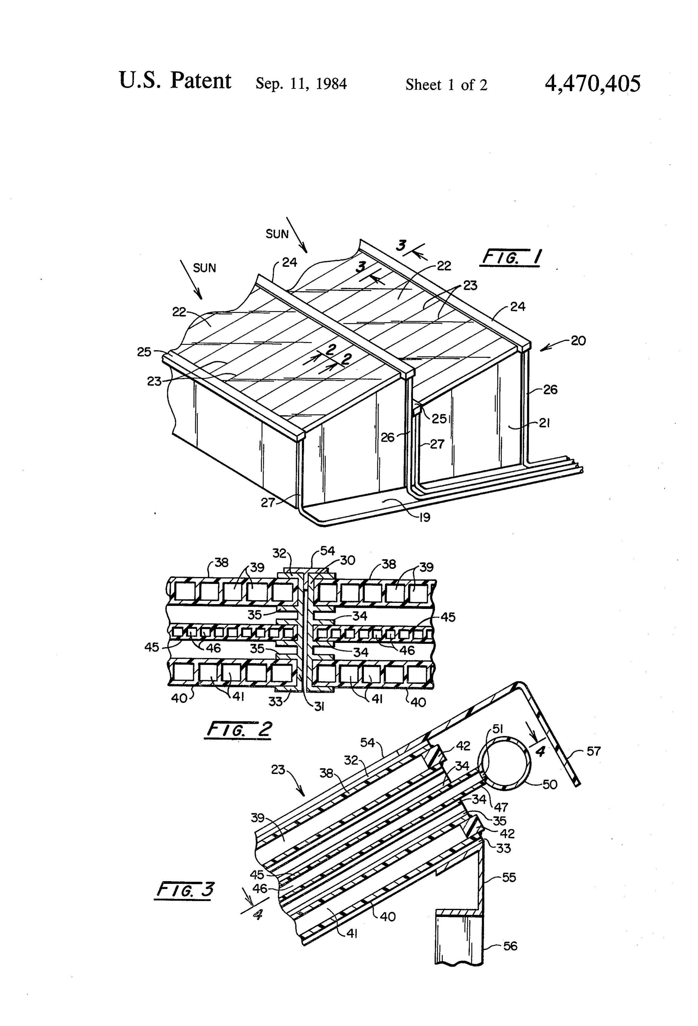
fulfillment of the building needs. It is a further object of Although the construction shown in FIG. 2 is a pre the invention to effect the desired controls by a combi 15 ferred embodiment, alternative frame assemblies 23 may nation of the above recited methods under some cir omit either external cover 38 or lower cover 40 or both. Cumstances. The omission of covers has the effect of reducing the Other objects and features of the invention will be insulating qualities of the frame assemblies, but in some apparent and understood from the detailed description situations, this may be satisfactory or desirable. of the invention and the accompanying drawings which 20 The rays of the sun in the ultraviolet spectrum (UV) follow. - are detrimental to many of the translucent materials that DESCRIPTION OF THE DRAWINGS are used in the construction of solar panels so that some means of protection may be used. This is accomplished
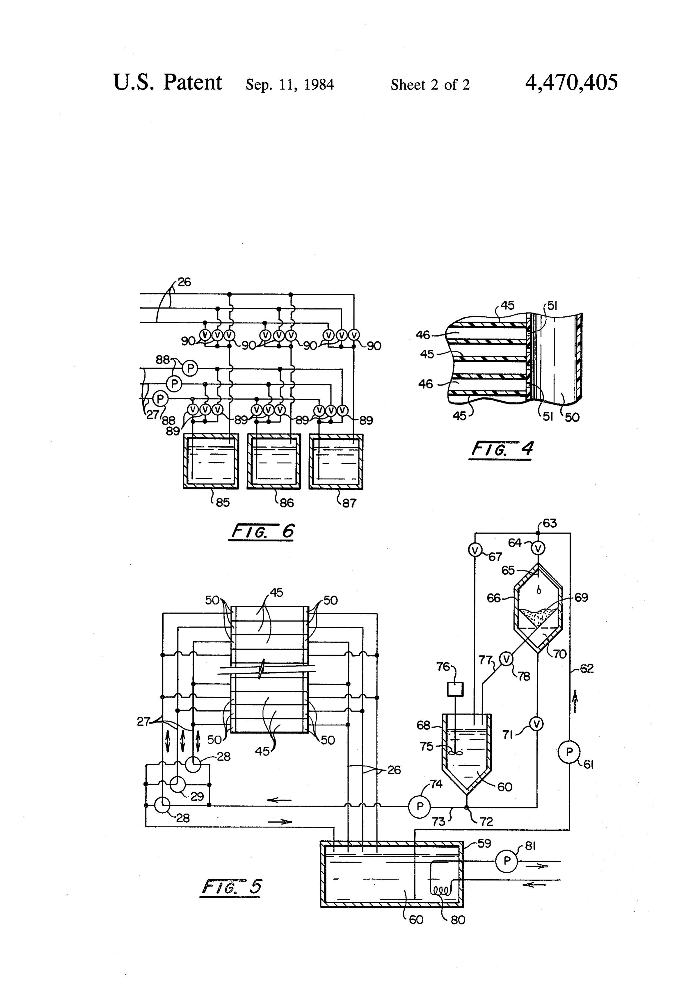
FIG. 1 is a perspective view of a typical building by adhering a UV filtering film to the outside of the having the apparatus of this invention and suitable for 25 panel 45, or cover 38. It may also be accomplished by employing the method of this invention. including UV filtering compounds in the formulation of FIG. 2 is a cross-sectional view of a portion of the the plastic materials from which the members are made. roof structure of the building, taken along the line 2-2 As seen in FIG. 3, the passageways 39 and 41 are of FIG. 1. closed at their upper ends, by sealing means 42. At the FIG. 3 is a cross-sectional view of a portion of the 30 opposite end (not shown), the passageways remain open roof structure taken along the line 3-3 of FIG. 1 to the atmosphere, providing insulating still-air spaces FIG. 4 is a cross-sectional view of a portion of the that reduce the overall heat transmission of the covers roof structure, taken along the line 4-4 of FIG. 3. 38 and 40, as well as the frame assembly 23 as a whole. FIG. 5 is a schematic view of the system of this inven A panel 45 is centrally positioned between the covers tion. 35 38 and 40, extending from one channel 30 to the other, FIG. 6 is a schematic view of another embodiment of supported in the flanges 34. The panel 45 is constructed the system. with integrally formed contiguous longitudinal conduits DETAILED DESCRIPTION OF THE 46 (the first conduits), which extend the entire length of
Invention
the panel 45 from the ridge end 24 to the eaves end 25.
40 The panel 45 projects beyond the end of the frame
Referring to FIG.1, building 20 is shown as employ assembly 23 in an extended portion 47, where it is joined ing a generally sawtooth roof line construction having to a common header 50 (the second conduit). The con walls 21 and a roof structure 22. A conventional gable duits 46 are in liquid fluid communication with the roof construction could also be used. The roof is made second conduits 50 through an orifice 51. up of elongated frame assemblies 23 generally longitudi 45 At the opposite end of the frame assembly 23, the nally oriented from a peak 24 to the eaves or valleys 25. panel 45 extends and is fitted with a header 50 in the The building rests on the ground 19. same fashion as that shown in FIG. 3. The building is generally oriented so that the rays of The panels 45 may vary in width, either containing the sun strike the frame assemblies 23 at an optimum only a few conduits and being relatively narrow, or angle, typically as near to 90 degrees at noon as possible 50 containing a large number of conduits and being much for the locality at the time of year of the maximum wider. In a preferred embodiment, by way of example, heating or cooling load. a panel was constructed approximately 60 centimeters Piping 26, connecting to the peaks 24, is provided wide and have conduits across the width. The panels from the ground 19, for purposes to be described later in are constructed of molded or extruded polysulfone further detail herein. In the like manner, piping 27 is 55 plastic material, a specially compounded polymer. connected to the eaves 25. Other plastic materials can be used. Referring to FIGS. 2, 3 and 4, the roof frame assem Each panel 45 is provided with an individual header blies 23 comprise channel formed side members 30 hav 50, extending the width of the panel. ing a web 31, outstanding top flanges 32, bottom flanges As seen in FIG. 1, frame assemblies 23 are in adjacent 33 and central track flanges 34 and 35, respectively. An side-by-side position, and may be sealed on the outside external generally flat cover 38 is constructed to fit with a rubber-like T-shaped sealing element 54 or other longitudinally the length of the frame assembly 23 and means. The frame members 23 may be supported on a between the exterior flange 32 and the track flange 35. common channel beam 55 which is carried by a column Cover 38 is constructed as an extrusion of a tran 56. A suitable ridge cover 57 is formed over the header slucent/transparent plastic material and is provided 65 50 and joined to the upper corner of the frame members with longitudinal passageways 39 extending the length 23, as shown in FIG. 3.
of the cover from the ridge 24 end to the eaves 25 end. Referring to FIG. 4, the second conduits 50 are con The material from which the cover 38 is formed may be nected to the first conduits 46 through flow control 6 orifices 51 which provide a reasonably uniform flow to control the rate of insolation transmission through distribution across the panel 45. the panels 45 and into the building interior. Referring to FIG. 5, in the complete system shown For instance, when there is a maximum need for shad schematically, the second conduits 50 are connected to ing the building interior because conditions in the the panels 45. greenhouse will permit or require at or near total dark Each header 50 on the lower end of the panel 45 is ness in the greenhouse, opaquing material from the filter connected through piping 27 to a valve means 28, 29, 69 is conveyed under control of the valve 76 to the and to a reservoir 59 containing a "black' liquid 60. A mixing tank 60 where it is blended into the liquid by the pump 61 is connected through piping 62 to a junction O mixer 75 with the valve 71 closed. The pump 74 con 63. The junction 63 is connected on one side through a veys black liquid in its most opaque condition through valve 64 to an inlet 65 of a filter tank 66. The other side the piping.27 to the header 50 and through all of the of the junction is connected through a valve 67 to an panels 45 simultaneously, with all of the valve means 28, inlet in a mixing tank 68 which contains a further source 29 in the open-to-pump position. Continuous operation of black liquid 60. A mixer 75 may be suspended in the 15 in this condition causes the black liquid 60 to com mixing tank 60 operated by an electric motor 76. pletely shut out all sunlight from passing through the In the filter 66, opaquing material 69 is filtered from panel 45 while simultaneously allowing the liquid to . the black liquid, leaving a relatively clear liquid 70 in absorb heat at its maximum rate and convey that heat to the lower portion of the filter tank 66. The stored clear the reservoir, and source 59 for use through the heat liquid 70 is connected through a valve 71 to a junction exchanger 80. - 72 at the outlet of the mixing tank 68. Piping 73 con 20 In the event that plant life in the greenhouse requires nects with a pumping means 74 that is connected with the admission of some insolation and the other condi the valve means 28, 29. tions previously stated remain, the amount of opaquing A heat exchanger 80 is submerged in the black liquid material passing through the panels may be reduced to 60 in the reservoir 59. The heat exchanger is connected provide less shading and some solar radiation directly to another working fluid which is moved by means of through the roof to the plants beneath. This is accom pump 81, to an apparatus for useful work such as heat plished by turning valve means 28, 29 in selective com ing or cooling the building. binations. For instance as shown in FIG. 5, alternate In operation of the apparatus and the system, the valve means 28, 29, are turned. Valve means 29 is turned black liquid; i.e. a liquid containing an opaquing mate 30 to allow all liquid to drain from the panels to which it is rial, is conveyed by the pump 61 through piping 62, connected, and allow the sunlight to pass through those where it is proportionally directed as necessary and panels. Accordingly, in the operating mode shown in under control of valves 64 and 67 to either the filter tank FIG. 5, direct sunlight is admitted through every other 66 or the mixing tank 60. That portion which is directed panel 45.
to the filter tank 66, is filtered, and the clear liquid 70 is 35 Of course, other combinations may be selected to conveyed to the junction 72. admit more or less direct sunlight. That portion, which is directed to the mixing tank, is In other circumstances, such as when the sun is di blended with opaquing material from the filter 69 rectly overhead and of maximum intensity as in the through piping 77 under the control of valve 78 to the summertime, it may be desirable to control the rate of mixing tank 60. insolation transmission through the panels 45, by vary Clear liquid 70 is blended with the mixture from the ing the amount of opaquing material in the panel, by mixing tank 60 at the junction 72, and is conveyed by selectively removing a portion of the opaquing material the pump 74 through the valves 28, 29 and piping 27, to from the liquid. This is accomplished through diluting the inlet headers 50 wheree it is distributed to the panels the liquid from the mixing tank 60 by the admission of 45 under control of the valve means 28, 29. 45 clear liquid 70 at the junction 72, when liquid is being Valve means 28, 29, are bi-directional and may be conveyed to the header 50 by the pump. 74 and piping turned to direct liquid from the pump 74 into the head 26. When the liquid is diluted, the solar radiation is ers 50 and panels 45, as valves 28 are shown, or may be filtered in certain wave lengths, depending on the kind turned to allow the panels 45 and headers 50 to drain of liquid and the kind of opaquing material being used. back to the reservoir 59, as valve 29 is shown. 50 The use of diluted liquid, i.e. shading, in this way is Referring to FIG. 6, in another embodiment of appa useful in providing the right condition for plant growth ratus to carry out the method of the invention, a plural in Depending the greenhouse.
on plant growing conditions, atmospheric ity of reservoirs 85, 86 and 87 may be employed. Each reservoir contains a liquid of a different dilution of conditions, the amount of solar radiation available, the materials. A system of pumps 88 and valves 89 are con 55 amount of heating or cooling load or other useful work nected to the inlet piping 27. A plurality of valves 90 are requirements, the control may selectively be either the connected to the outlet piping 26. When a liquid of a number and combination of panels containing liquid or certain dilution is needed, liquid is selectively pumped the amount of opaquing material in the liquid or both in from the appropriate reservoir through the system. This combination.
is accomplished by operating the appropriately It will be apparent that the degree of variation under matched pumps 88 and valves 89,90, that are associated infinitelybyvariable control the method of this invention is a substantially analog, from a maximum transmitted with the appropriate headers 50, panels 45 and reser insolation effected by circulating clear liquid or admit voirs 85, 86, 87. In this embodiment of operation, the ting no liquid, to the opposite extreme of circulating variety of control parameters is limited by the number completely of reservoirs. 65 opaque liquid through all conduits 46. The objectives of the invention are met by operation While the combination of both methods provides a of the system, and controlling the flow of the liquid maximum degree of control, the use of either is advanta through the various component apparatus of the system geous.
Page 7scan →
Another advantage of the method, apparatus and a, a roof structure including frame assemblies of system of this invention is its integration with the hea translucent insolation passing material constructed ting/cooling system of the building. Not "only is the into separate panels with contiguous integrally liquid 60 in the reservoir 59 supplying heat to the heat formed common header first conduits at one end of exchanger 80, it is also acting as a medium of insolation 5 the panels in liquid fluid communication through control through the roof of the building. the panels with common header second conduits at Still another advantage of this invention is that the opposite ends of the panels, the system including a insulation values of the panels are increased when the plurality of valves, each connected to a first con panels are drained of liquid and contain only air. This O duit and operable in selected combinations to admit means if additional insulation is needed, the entire sys the liquid to various combinations of the panels; tem may be drained of liquid to gain better heat reten b. a source of liquid containing an opaquing material tion inside the building and protection against low or selected to enhance the insolation blocking opacity high temperatures outside the building. properties of the liquid, the source having means Still another advantage of the method and apparatus for varying the opacity of the liquid including a of this invention is in the use of clear liquid throughout 15 reservoir for the liquid and a filter apparatus for the the system whereby the insolation in the visible light liquid, the filter apparatus being arranged to re spectrum is increased when desired. It has been found move opaquing material from the liquid or add that circulating clear liquids in the conduits 46 of the opaquing material to the liquid prior to conveying panels 45 increases the transmission of visible light pro 20 the liquid through the first and second conduits; viding even better growing conditions for the plants in c. the system for conveying the liquid from the source the greenhouse than when the conduits are empty when through the second and first conduits including a external insolation levels are marginal. pump connected to the first conduits through the EXAMPLE valves and connected to the reservoir, through the filter apparatus with the second conduits being
An example of a black liquid that was tested and 25 connected to the reservoir; and , found suitable for use in this invention is shown below d. the valve, pump, and filter apparatus being operat in Table 1. able selectively in combinations to control the rate TABLE 1 of insolation transmitted into the building by vary 30 ing the amount of opaquing material passing
SPECIFICATIONS OF WATER-BASED through the roof structure:
BLACKLIQUID CONCENTRATE (i) by varying the amount of opaquing material in Tradename Designation: PERMABLAK 663 by
Mono-Chem Corporation, Atlanta, Texas 75551 the liquid by adding or removing opaquing mate Percent Carbon Black by Weight 14% rial in the filter apparatus, or Total Solids 51.9% 35 (ii) by varying the number and combination of panels Type Black High Color Furnace. passing liquid by pumping the liquid through the : Particle Diameter of Black 13 Nanometers, valves in selected combinations, or Type Dispersing Agent Nonionic pH 10.0-11.5 (iii) by combining the variations of (i) and (ii) simul Weight per Gallon 9.75 pounds -- 5% taneously;
e. the combinations being selected according to pre . . When mixed with water, the above specified black selected optimum fulfillment of the combined heat liquid provides solar absorptivity as shown in Table 2 ing, cooling, and insolation needs of the building, below. under varying atmospheric conditions having in fluence on the building.
.. . .. TABLE 2 45 2. An insolation controlling apparatus according to SOLARABSORPTIVITY OF BLACK LIQUEDS claim 1, wherein the panels are located between insulat Percent of ing still-air spaces formed between internal and external
Dilution Ratio Original Solar. Absorptivity translucent roof covering members. (Parts Black Black Liquid for 1 cm. Thickness 3. An insolation controlling apparatus according to
.50 claim 1, wherein the building is a greenhouse.
1:0, ... 100 100 4. An insolation controlling apparatus according to
:3 25 ..100 claim 1, wherein heat exchange apparatus is provided in i 17, 12, ". . ; 100 the reservoir to extract heat from the liquid therein to heat or cool the building or perform other useful work.
1:30. 3 55. 5. An insolation controlling apparatus in a building having varying, insolation, heating and cooling needs,
It is herein understood that although the present in constructed with an exterior wall structure and a roof vention has been specifically disclosed with the pre structure spanning between the walls, comprising:
ferred embodiment and examples, modifications and a. a roof structure including frame assemblies of variations of the concept herein disclosed may be re 60 translucent insolation passing material constructed sorted to by those skilled in the art. Such modifications into separate panels with contiguous integrally and variations are considered to be within the scope of formed common header first conduits at one end of the invention and the appended claims. the panel in liquid fluid communication through What is claimed is: , the panels with common header second conduits at 1. An insolation controlling apparatus in a building 65 opposite ends of the panels, the system including a having varying insolation, heating and cooling needs, plurality of valves, each connected to a first con constructed with an exterior wall structure and a roof duit and operable in selected combinations to admit structure spanning between the walls, comprising: the liquid to various combinations of the panels;
Page 8scan →
b. a source of liquid containing an opaquing material selected to enhance the insolation blocking opacity properties of the liquid, the source having means for varying the opacity of the liquid including a plurality of separate reservoirs, each reservoir con taining a liquid having a different insolation block ing opacity for the liquid;
. the system for conveying the liquid from the source through the second and first conduits including a pump connected to the first conduits through the 10 valves and connected to the reservoirs with the second conduits being connected to the reservoirs; and d. the valve, pump, and plurality of reservoirs being operable selectively in combinations to control the 15 rate of insolation transmitted into the building by varying the amount of opaquing material passing through the roof structure:
(i) by varying the amount of opaquing material in the liquid by selection of a reservoir from which to pump the liquid, or (ii) by varying the number and combination of panels passing liquid by pumping the liquid through the valves in selected combinations, or (iii) by combining the variations of (i) and (ii) simul taneously;
the combinations being selected according to pre selected optimum fulfillment of the combined heat ing, cooling, and insolation needs of the building, under varying atmospheric conditions having in fluence on the building.
Provenance
- Collection
- Patents citing this work
- Pages
- 8
- Method
- pdftotext (the PDF's own text layer) + pdftoppm 300dpi page scans
- Patent office record
- patents.google.com →
- Source
- Google Patents citing-documents table
- Assignee
- Battelle Memorial Institute
- Published
- 1984-09-11
- Transcribed from
- patentimages.storage.googleapis.com →