

patent · US4482448A
Electrode structure for electrolyser cells
13 November 1984
Text
Page 1bibliographic recordscan →
United States Patent (19)
Bowen et al.
54 ELECTRODESTRUCTURE FOR
ELECTROLYSER CELLS
(75) Inventors: Christopher T. Bowen, Pointe Claire; H. John Davis, Beaconsfield; Rodney
L. LeRoy, Pointe Claire, all of
Canada Assignees: Noranda Inc.; The Electrolyser
Corporation Ltd., both of Toronto,
Canada
(30) Foreign Application Priority Data
Dec. 23, 1981 (CA) Canada ................................... 393109 Int. Cl............................................... C25B 11/03 52 U.S. Cl. ..................................... 204/284; 204/286
3,019,178 1/1962 Williams .............................. 204/284 3,123,545 3/1964 Williams .............................. 204/284 3,379,634 4/1968 Rutkowski ...... ... 204/258
3,941,675 3/1976 Strasser et al. ...................... 204/256 4,008,143 2/1977 Kircher et al. ..................... 204/257
FOREIGN PATENT DOCUMENTS
Primary Examiner-G. L. Kaplan
Assistant Examiner-Nam X. Nguyen
Attorney, Agent, or Firm-Fleit, Jacobson, Cohn & Price
An electrode structure for electrolytic cells is disclosed. The electrode structure comprises a central current-col lector structure having high points on at least one side and adapted to be placed vertically in the electrolytic cell, and a porous electrode secured to the high points of the current-collector structure on at least one side thereof so as to form an essentially-planar pre-electrode surface. The high points of the current-collector are arranged so as to allow an unimpeded rise of the evolved gases to the top of the electrode.
5 Claims, 4 Drawing Figures
Drawings
Page 2drawing sheetscan →
Page 3drawing sheetscan →
Page 4scan →
the purpose of providing support to the pre-electrode
ELECTRODESTRUCTURE FOR ELECTROLYSER when a diaphragm material is being deposited on the CELLS electrode surfaces under vacuum. However, the inter nal support structure of these electrodes is not con
This invention relates to an electrode structure for 5 nected to current removal structures and, more impor electrolyser cells, more particularly of the unipolar tantly, not designed to carry currents in the order of type. 1000 to 10,000 amperes or more, such as required in It is well known that the voltage of an electrolytic industrial unipolar electrolyser cells. cell is the sum of three major components: the thermo The pre-electrode elements are often attached to dynamic potential required for the overall cell reaction; 10 central current-collector structures, for example rods or the electrode overvoltages which result from kinetic an equivalent fabricated structure in the unipolar design limitations; and a resistive contribution to cell voltage. as disclosed in Canadian Pat. No. 1,041,040, issued Oct. For a particular desired process, the major avenues 24, 1978, or a formed bipolar plate in bipolar electroly open for reduction of energy requirements are electrode ser equipment, as disclosed in U.S. Pat. No 3,379,634, activation to reduce the overvoltages for the desired 15 issued Apr. 23, 1968. These electrode designs are, how reactions, and design improvement to reduce resistive ever, not adequate for electrolyser cells because they do losses. not allow efficient removal of gases up the electrode. Resistive losses are of two types: ionic, reflecting a U.S. Pat. No. 4,008,143 discloses an electrode structure resistance to the passage of current in the electrolyte; comprising two spaced porous pre-electrodes and a and electronic, reflecting the resistance to the passage 20 plurality of current conductive rods separately attached of current in current-carrying metallic components of to each porous pre-electrode and positioned in the space the electrolyser. In bipolar electrolyser designs, the between the porous pre-electrodes in such a way as to ionic resistance contribution is of overwhelming impor leave space for electrolyte to flow upwardly between tance, since current paths through metallic elements are the porous pre-electrodes. However, electrolyser cells normally very short in length. In equipment of the uni 25 would require a large number of current conductive polar design, however, electronic resistance losses can rods in order for the pre-electrodes to carry currents in become substantial, as the electronic current is normally the order of 1000 to 10,000 amperes and more, and this removed from each electrode to a current-removal would unduly restrict gas circulation between the po structure. rous pre-electrodes.
In designing to control ionic resistance of an electro 30 It is therefore, the object of the present invention to lyser, two considerations are particularly important: provide an electrode for electrolyser cells which has the minimization of the distance between the anodic and following characteristics:
cathodic electrode elements; and minimization of the (a) Allows efficient removal of gases formed on the quantity of evolved gases which is retained between the outer faces of the electrode surface to the interior electrodes, increasing the effective electrolyte resistiv 35 of the electrodestructure and up the electrode ity. This latter requirement can be particularly impor structure under the influence of their natural buoy tant in cells having gas separating elements or dia ancy in the electrolyte, thus reducing the ionic phragms, where gas may accumulate in the separator or contribution to electrolyser voltage. on its surface, thus increasing its resistance. (b) Allows current to be removed from each elec A design approach directed at satisfying these two 40 trode while minimizing electronic resistance losses. requirements for minimizing ionic resistance, which has (c) Is amenable to fabrication by low-cost techniques come into widespread use, is to use a porous pre-elec such as rolling, stamping and welding, thus provid trode structure on which the gas evolves, and which ing an economic electrode. allows passage of the product gases through the struc (d) Allows use of low-cost materials of construction ture to a rear area where they can be removed. Typical 45 having regular surfaces which can be reliably and pre-electrode forms are perforated plates, expanded economically protected from corrosion in the elec metal sheet, and woven metal cloth. Any suitably-por trolyte by the electroplating of nickel or other ous structure can be envisaged, including grooved corrosion-resistant coatings. sheets on foam metal. (e) Has a thin profile, to be consistent with an electro A number of designs make use of porous pre-elec 50 lyser design for minimum size per unit of produc trodes of this type which are fabricated from material tion capacity.
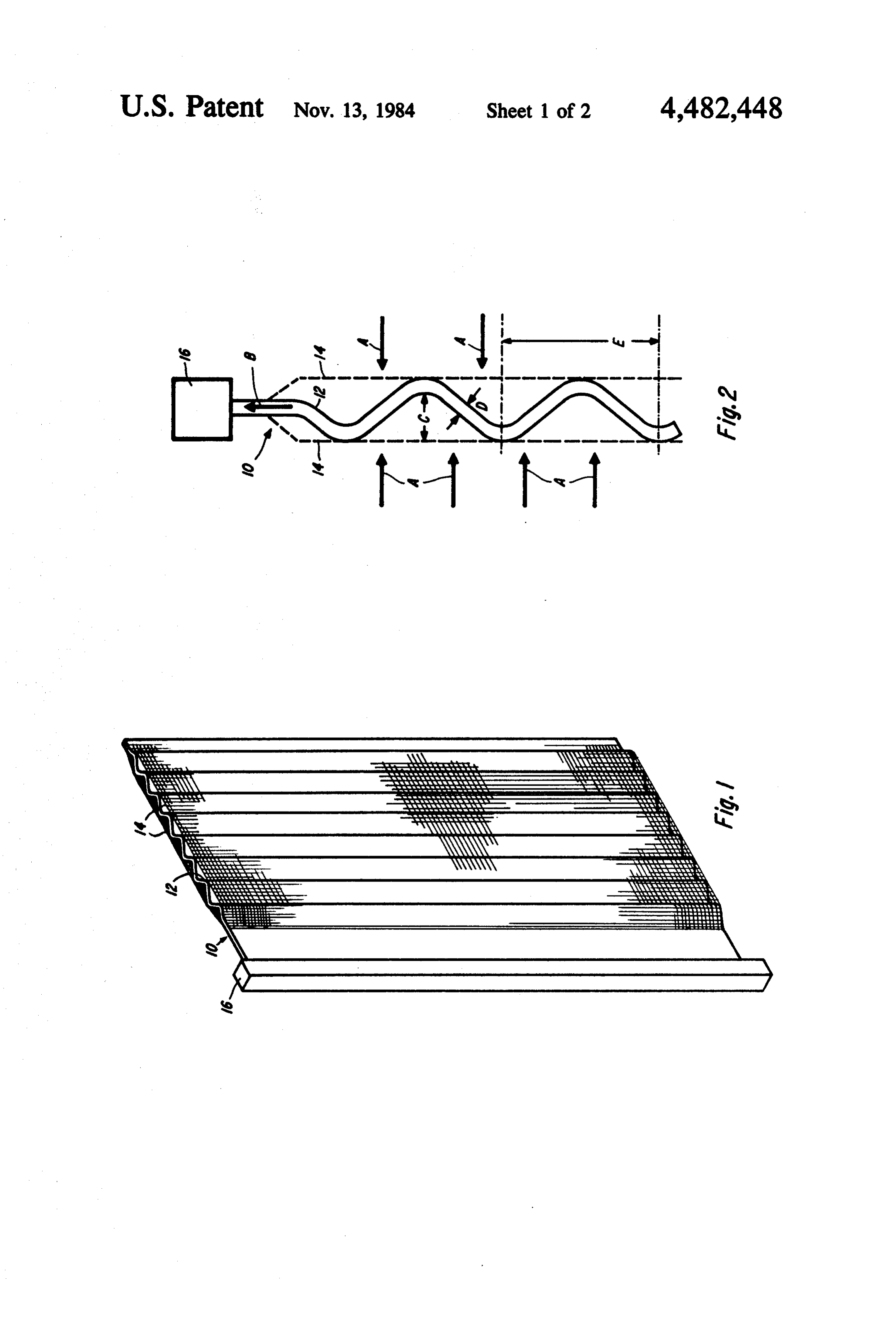
which is sufficiently strong to be used without support, The electrode structure, in accordance with the pres and which can be attached directly to a current-remo ent invention, comprises a central current-collector val structure at the periphery of the electrode. An ex structure having high points on at least one side thereof ample is Canadian Pat. No. 822,662, issued Sept. 9, 1969. 55 and adapted to be placed vertically in the electrolytic However, these pre-electrodes do not have the current cell, and a porous electrode secured to the high points removal capacity which is required for industrial unipo of the current-collector structure on at least one side lar electrolyser cells. - thereof so as to form an essentially-planar pre-electrode Several inventors have recognized the desirability of surface. The high points of the current-collector struc using a supporting structure as part of the electrode, in 60 ture are located on the central current-collector so as to order to accomplish desirable mechanical objectives. allow an unimpeded rise of the evolved gases to the top For example, Canadian Pat. No. 1,002,476 issued Dec. of the electrode.
28, 1976, discloses the use of a thin corrugated structure, The central current-collector is preferably a plate internal to the pre-electrode, to provide a spring effect having vertically oriented corrugations and the pre and improve the compression of anode/separator/cath 65 electrode is secured to the crest of such corrugations. ode array while allowing for flexibility during cell as The invention will now be disclosed, by way of exam sembly. Canadian Pat. No. 1,086,256, issued Sept. 23, ple with reference to the accompanying drawings in 1980, features the use of a similar internal structure for which:
Page 5scan →
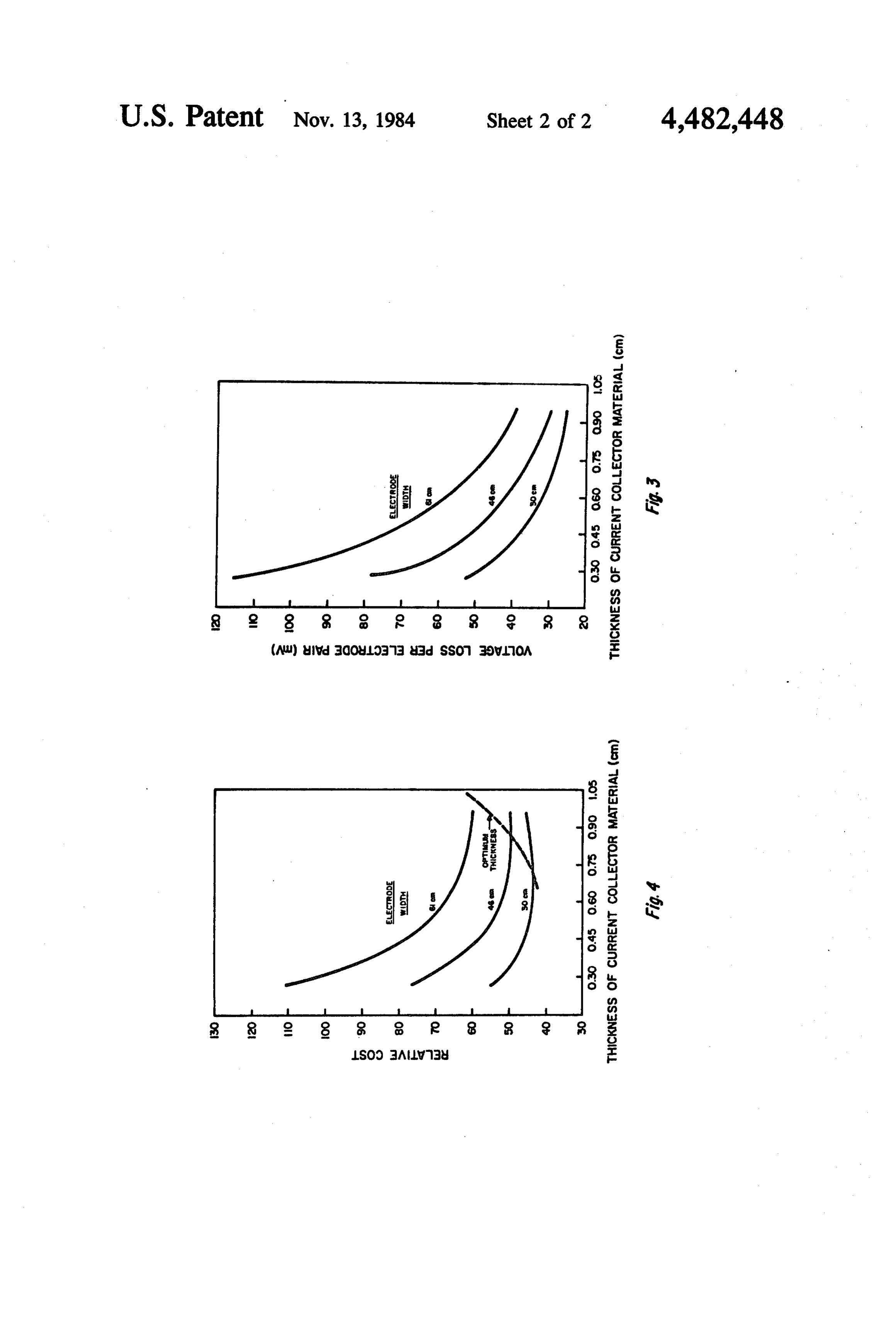
FIG. 1 is a perspective view of an electrode in accor nomic forming of the current-collector material. This is dance with the invention; necessary to minimize resistance losses in the pre-elec FIG. 2 is a plan view of a portion of the electrode of trode structure. The length of corrugation might be FIG. 1; and between 0.7 and 15 cm for a current-collector material FIGS. 3 and 4 illustrate typical optimization curves having a thickness of between 0.04 and 1.5 cm. for an electrode from which current is being removed Other dimensions of the current-collector structure uniformly at the side. can be established through a detailed optimization to Referring to FIGS. 1 and 2 of the drawings, there is minimize total operating cost, including capital amorti shown a gas evolving electrode 10, anode or cathode zation. Each of the major electrode parameters can be which comprises a central current collector 12 to each O optimized in this way: thickness of the material from side of which is attached a pre-electrode 14. Ionic cur which the current collector is formed, width of the rent flow from the adjacent electrode or electrodes of electrode, and, depending on the detailed method being opposite polarity would flow to the electrode perpen used for current removal, dimensions of the current dicular to the pre-electrode structures, as shown by equalization or removal bar 16 and the electrode height. arrows A, and current is removed from the pre-elec 15 FIGS. 3 and 4 illustrate a typical optimization, for an trodes by the current collector 12, as indicated by arrow electrode from which current is being removed uni B. formly at the side. The anode and cathode are assumed The pre-electrodes are normally woven screen, ex to be of similar design. The contribution to cell voltage panded metal, or perforated plate but can be of any due to electronic resistance of the current-collector other perforated or porous geometry which allows for 20 structure (FIG. 3) diminishes as the thickness of the gas passage through the structure to the interior of the current-collector material is increased, or as the width electrode. of the electrode is reduced. Such voltage contributions The central current-collector is a solid, formed metal can be calculated unambiguously by the method de piece which is illustrated as being corrugated, although scribed by R. O. Loutfy and R. L. LeRoy in the Journal any structure which could be formed in an economic 25 of Applied Electrochemistry 8 (1978) pages 549-555. manner, and which allows for unimpeded rise of the The results presented assume that the material of con evolved gases to the top of the electrode, would be struction is mild steel at 70° C., and that the current within the scope of the invention. density on the projected pre-electrode structure is 240 The pre-electrode is attached to the central current mA/cm2.
collector at the high points of the structure so as to form 30 FIG. 4 shows a typical optimization, in this case as an essentially-planar pre-electrode surface. The attach suming a current price for mild steel and a power cost of ment may be by a weld, by screws or other mechanical $0.03/kWh. The optimum electrode thickness is seen to fasteners, or by pressure which is exerted by the com increase with increasing electrode width. Of course the posite electrode/separator mass. optimum values indicated by calculations such as these The central current collector must be attached at one 35 will have to be modified based on other considerations end to the elements removing current from the elec related to the overall dimensions of the electrolyser, the trode. This attachment may be continuous, through a method of current removal, etc.
welded, bolted, or riveted contact, or it may be at sev It must be noted that the formed current-collector eral points through connections to suitable conductors. structures of this invention are in no way related to In this latter case, additional current-conducting mate 40 formed structures described in the prior art, which have rial may be included in the structure, as indicated by bar been used for mechanical purposes such as compression 16, to assist current equalization in the vertical direc of the electrode mass. The electrodes of this invention tion, to further minimize resistive losses. are designed to carry currents of 1,000 to 10,000 am In any particular electrolyser design, the parameters peres and more, and precise specification of the current of the electrode of this invention are established by an 45 removal provisions is essential to achieve an economic optimization which considers the resistive losses in the result. Similarly, the massive quantities of gas evolved structure, the cost of the material of construction, and at such current loadings must be free to move unim the physical constraints imposed by the detailed electro peded up the electrode to escape at the top. None of the lyser design on maximum and minimum electrode thick proposals of the prior art accomplish these two objec ness. It has been surprisingly found that a depth of the 50 tives.
corrugations C (FIG. 2) as low as 0.16 cm is satisfactory We claim:
for electrode heights as great as 75 cm, with gas evolu 1. An electrode structure for unipolar electrolytic tion at current densities to 1,000 mA/cm2; no increase in cells comprising:
the ionic-resistance factor of the electrolyser was de (a) a formed metal plate current-collector structure tectible with increasing current density, suggesting that 55 having vertically orientated corrugations which the product gas is being effectively removed to the define a plurality of respective crests and adapted interior of the electrode structure. However, the depth to be placed vertically in the electrolytic cell; of corrugations would likely not be less than 0.1 cm. (b) a porous electrode secured to the crests of said The maximum depth of corrugation would be estab corrugations on at least one side thereof so as to lished by practical constraints on electrolyser size; it 60 form an essentially-planar pre-electrode surface, would be unlikely that a depth of corrugation greater the depth of said corrugations being such as to than 3 cm would be desirable. allow an unimpeded vertical rise of evolved gases The thickness D (FIG. 2) of the current collector to the top of the electrode between the corrugated material may be between 0.04 and 1.5 cm depending on plate and the pre-electrode surface; and the amount of current to be removed from the elec 65 (c) means for removing or applying current from one trode. The length E (FIG. 2) of the corrugation waves, vertical end edge of said plate. or the spacing of the high points of equivalent formed 2. An electrode structure as defined in claim structures, will be the minimum consistent with eco wherein said means for removing current from one 6 vertical end edge of said plate includes a bar secured to wherein the thickness of said plate is between 0.04 and said vertical end edge for current equalization. 1.55.cm.
An electrode structure as defined in claim. 4, 3. An electrode structure as defined in claim 1 or 2 wherein the length of said corrugations is between 0.7 wherein the depth of corrugation of the electrode is 5 and 15cm for a plate having a thickness of between 0.04 between 0.1 and 3 cm. and 1.5 cm.
4. An electrode structure as defined in claims 1 or 2 is k a k k
Provenance
- Collection
- Patents citing this work
- Pages
- 6
- Method
- pdftotext (the PDF's own text layer) + pdftoppm 300dpi page scans
- Patent office record
- patents.google.com →
- Source
- Google Patents citing-documents table
- Assignee
- Noranda Inc.
- Published
- 1984-11-13
- Transcribed from
- patentimages.storage.googleapis.com →