

patent · US4491714A
Method of and apparatus for electrical discharge machining using a gas dissolved water liquid
1 January 1985
Text
Page 1bibliographic recordscan →
United States Patent (19)
Inoue
(54) METHOD OF AND APPARATUS FOR
ELECTRICAL DISCHARGE MACHINING
USING A GAS DISSOLVED WATER LIQUID
Inventor: Kiyoshi Inoue, Tokyo, Japan Assignee: Inoue-Japax Research Incorporated,
Yokohama, Japan
(30) Foreign Application Priority Data
Juli. 24, 1981 (JP) Japan ................................ 56-11555 Int. Cl. ................................................ B23P 1/08 52 U.S. C. ................................. 219/69 D; 204/129;
3,420,759 l/1969 Inoue ................................ 219/69 d
3,553,415 l/1971 Girard .............................. 219/69 D 3,616,436 10/1971 Haas .................................... 204/129 3,626,137 12/1971 Bertolasi ........ ... 219/69 D 3,928,163 12/1975 Ullmann et al. ... ... 219/69 D 3,939,321 2/1976 Bertrand et al. .. ... 219/69 D 3,994,790 l 1/1976 Inoue ................................... 204/130
4,184,931 1/1980 Inoue ................................... 204/129 4,205,213 5/1980 Inoue ..... 219/69 W 4,263, 12 4/1981. Aylward ............................. 204/129
FOREIGN PATENT DOCUMENTS
2056492 5/1977 Japan ................................ 29/69 D 53-121293 10/1978 Japan ................................ 219/69 D
RFrograTOR
CIRCUIT
Tempera TuRs
CONTRO, UN
Primary Examiner-C. L. Albritton
Assistant Examiner-Geoffrey S. Evans
Attorney, Agent, or Firm-Karl F. Ross
A novel EDM method is disclosed in which a gas such as compressed air is dissolved in a water liquid to form a solution which is pumped into the machining gap formed between a tool electrode and a workpiece. An EDM power supply provides a succession of electrical discharges across the gap through the supplied solution to electroerosively remove stock from the workpiece with the decomposition of oxygen and hydrogen gases from the water liquid. The dissolved gas in the solution is liberated in the machining gap upon exposure to the electrical discharges to add to these gases, thereby in creasing the electroerosive stock removal. The gas is dissolved into the water in an amount of at least 20% by volume of the oxygen and hydrogen gases normally decomposed from the water liquid by the electrical discharges. An apparatus for executing the method includes a pressure chamber traversed by the pumped flow of the water liquid and having a gas supply inlet through which the compressed gas is introduced for solubilization in the water liquid. The region of the machining gap is preferably enclosed in a second pres sure chamber maintained under a superatmospheric pressure to limit the spontaneous liberation of the dis solved gas from the water liquid.
24 Claims, 1 Drawing Figure
crissure
WESS
Drawings
Page 2drawing sheetscan →
Page 3scan →
uid. Thus, it is observed that in EDM ranges designed
METHOD OF AND APPARATUS FOR to yield a surface roughness generally in excess of 10 ELECTRICAL DISCHARGEMACHINING USINGA uRmax, for the stock removal of 1 gram, kerosene pro GAS DISSOLVED WATER LIQUID duces gases in an amount of 1000 cc whereas water only
Field of the invention
produces gases in an amount of 333 cc. I have now recognized that it is because of this insufficiency of
The present invention relates generally to electrical gases produced in the machining gap that a water na discharge machining (EDM) and, more particularly, to chining liquid is inferior in removal rate and machining a new and improved method of and apparatus for the O stability to a hydrocarbon liquid and that if the water electrical discharge of a workpiece with a tool elec liquid is adapted in advance and forced by the gap elec trode juxtaposed therewith across a machining gap trical discharges, viz. by absorbing a substantial portion traversed by a machining liquid. of the discharge energy, to produce an additional BACKGROUND OF THE INVENTION amount of gases in the machining gap which can supple ment the oxygen and hydrogen gases normally decon
In electrical discharge machinining, it has been con 15 posed from water in the water-liquid EDM process, a monly recognized that a hydrocarbon liquid such as removal rate and machining stability approaching those kerosene or transformer oil provides a highly favorable with kerosene can be obtained. When a substantial por machining medium which can be introduced or sup tion of the energy (thermal and formed otherwise) of plied into the machining gap under pressure to serve as 20 machining electrical discharges is connected to create a the discharge medium, the coolant and the flushing desirable supplemental amount of gases in the machin medium. Unfortunately, however, such hydrocarbon ing the tendency to arcing even with a long-duration liquids are inflammable and must be used with anti-fire, pulse can be reduced and machining stability substan fire-alarm and fire-fighting equipment. tially improved. Furthermore, the added gases are insu The danger of a fire is entirely eliminated by the use lative both electrically and thermally, and hence can of a water liquid, which not only has widely been used 25 in traveling-wire EDM but is sometimes exploited in increase the dielectric strength, improve the dielectric sinking-type EDM as well. In addition to its nonin recovery characteristics and moderate the cooling abil flammability, it is readily available, is inexpensive and ity of the water machining medium. I have now discov entails a minimum problem of disposal. ered that the effective additional production of such There is, however, a problem with a water machining 30 gases can be produced in the machining gap when a gas liquid. Water is less satisfactory in stock removal and is in advance forcibly dissolved into a water machining machining stability than a hydrocarbon such as kero liquid.
sene. In the use of water, machining becomes unstable In accordance with the present invention there is and the removal rate drops noticeably when the dura provided, in a first aspect thereof, a method of electrical tion of discharge pulses is longer than 30 to 50 microsec 35 discharge machining a workpiece with a tool electrode onds. As the pulse duration is lengthened, an arc dis spacedly juxtaposed therewith across a machining gap charge more likely ensues with a water liquid having a traversed by a machining liquid, which method com specific resistance in the range between 103 and 5x 10⁵ prises: (a) dissolving a gas into a water liquid to produce ohn-cm than with a hydrocarbon liquid. Furthermore, a solution constituting the machining liuqid: (b) pump some electrolytic actions are inherent and cannot en ing the solution to supply it into the machining gap; and tirely be excluded when an electric current is passed through such a water machining liquid, thus limiting the (c) effecting a succession of electrical discharges across extent of dielectricity and dielectric gap recovery sivelygapremove the through the supplied solution to electroero stock from the workpiece with the conse which are essential in the EDM process and conse quential decomposition of said water liquid into oxygen quently limiting the desired machining stability. In addi 45 and hydrogen gases in the tion, it should be noted that machining instability with ting the dissolved gas in machining the gap while permit solution to be liberated water is attributed to its excessive cooling ability. therefrom only upon contact with the electrical dis OBJECTS OF THE INVENTION charges so as to be added to the oxygen and hydrogen Accordingly, the present invention seeks to provide a 50 gases, thereby increasing the electroerosive stock re new and improved EDM method which allows the moval. The gas may be air and should be dissolved in the effective use of a water machining liquid that is nonin flammable and eliminates the possibility of a fire and gap water liquid in advance and liberated in the machining which yet enables a workpiece to be machined with by electrical discharges in an amount of at least excellent stability and with a removal rate that has not 55 20% and, preferably, at least 50% in volume (calculated been achieved hitherto with such a liquid and that is at 1 atm) of the oxygen and hydrogen gases decom comparable with that attainable with a hydrocarbon posed by the electrical discharges from the water liquid machining liquid, especially but not exclusively in in the machining gap.
EDM ranges which entail the use of a discharge pulse The invention is especially advantageous in an EDM duration of at least 30 to 50 microseconds. process in which the water liquid is adapted to possess An object of the present invention also is to provide a specific resistance ranging between 103 and 5x 10⁵ an EDM apparatus for carrying out the improved ohm-cm and for a machining operation designed to method. yield a surface roughness of the machined workpiece in SUMMARY OF THE INVENTION excess of 10 uRmax or utilizing a pulse duration of the 65 electrical discharges of at least 30 microseconds.
I have observed that there is a difference in the In order to facilitate dissolution of the gas into the amount of gases produced in the EDM gap between the water liquid, it is desirable that the water liquid prior to use of a hydrocarbon liquid and the use of a water liq accepting the gas be cooled to less than a predetermined 4 temperature, that is 20° C., preferably 10° C. and more SPECIFIC DESCRIPTION preferably 5 C.
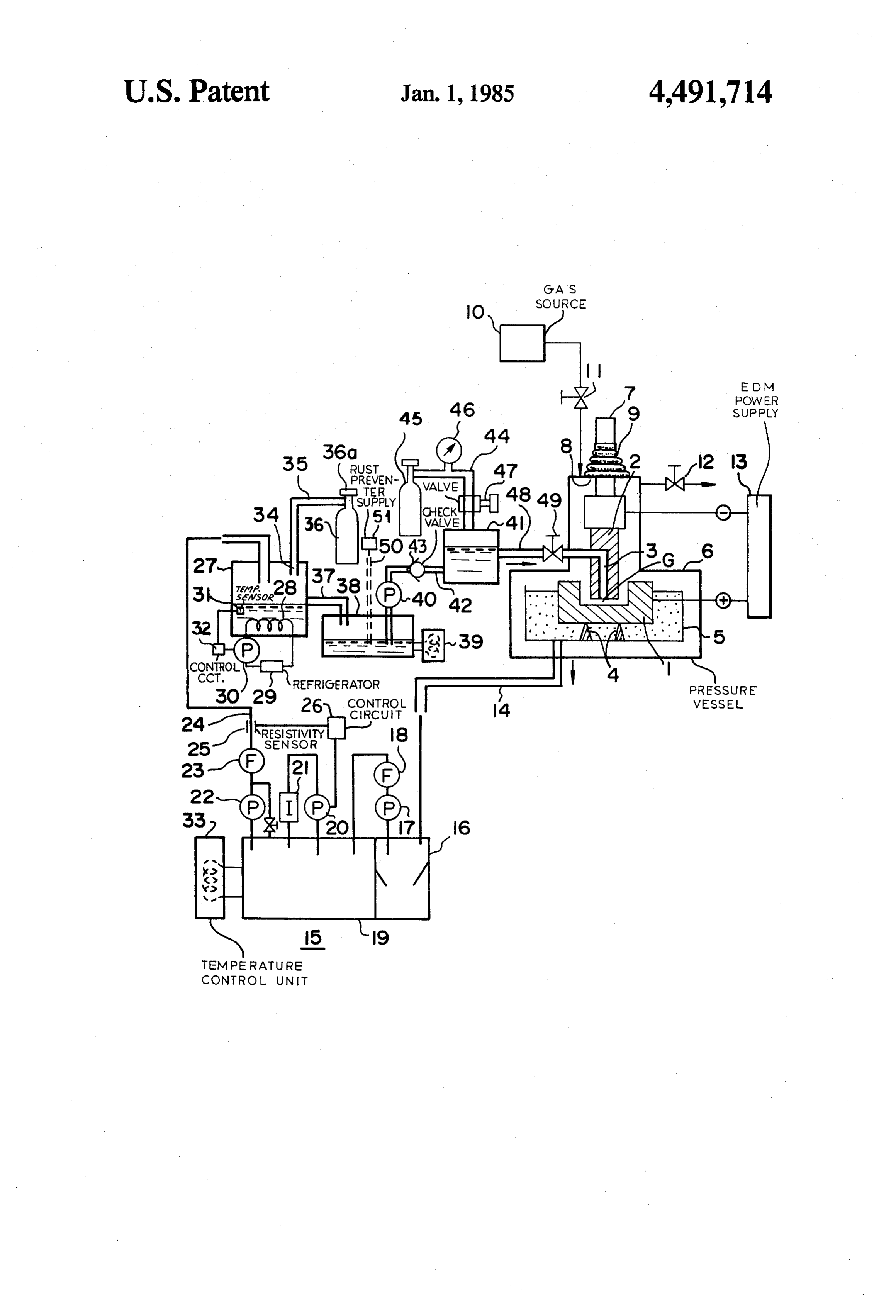
The gas is preferably dissolved into the water liquid In the drawing a workpiece 1 is shown as being ma by passing a pumped flow of the water liquid through a chined with a tool electrode 2 to aquire a cavity com volume of the gas compressed under a predetermined plementary in shape thereto. The tool electrode 2 has a pressure, that is at least 2 atms and preferably in excess fluid passage 3 formed therein which is open to a ma of 5 atms. chining gap G defined between the tool electrode 2 and Furthermore, it has been found to be critical to limit the workpiece 1. Although only one passage 3 open to the gap G is shown, two or more such passages may be the spontaneous liberation of the dissolved gas from the 10 formed solution issuing from the machining gap. To this end, and areainofthethetool electrode 2 depending on the shape machining surface thereof.
the method of the invention preferably includes main The workpiece 1 is mounted on a base 4 in a work pan taining the region surrounding the machining gap under a superatmospheric gaseous pressure of at least 2 atms 5pressure-resistant which is, in turn, received in a tightly sealed, rigid, vessel or receptacle 6. A spindle 7 and preferably in excess of 5 atms. The solution should 15 which carries the tool electrode 2 is led out of the recep be pumped to flow into the machining gap at a volume tacle 6 through an opening 8 formed in the upper wall flow rate of 5 to 10 liters/minute.
thereof. A bellows 9 is shown
The invention also provides, in a second aspect with the receptacle 6 while hermetically coupling the spindle 7 thereof, an apparatus for electrical discharge machining space inside the latter from the atmosphere. Asealing the a workpiece with a tool electrode spacedly juxtaposed 20 of pressure gas is connected to the receptacle 6 via10asource therewith across a machining gap traversed by a ma chining liquid, which apparatus comprises: means (a) valve through 11. The pressure in the receptacle 6 is adjusted a vent valve 12.
for dissolving a gas into a water liquid from a supply to produce a solution constituting the machining liquid; of electrical power
An EDM supply 13 for furnishing a succession pulses of adjustable parameters, i.e. pulse pumping means (b) for supplying the solution into said 25 duration, pulse interval and pulse peak current, has one machining gap; and means (c) for effecting a succession terminal electrically connected to the tool electrode 2 of electrical discharges across the machining gap and the other terminal electrically connected to the through the supplied solution to electroerosively re workpiece 1 to produce time-spaced electrical machin move stock from the workpiece with the consequential ing discharges across the machining gap G in the pres decomposition of the water liquid into oxygen and hy 30 ence of a machining liquid which in accordance with drogen gases in the machining gap while permitting the the present invention is basically constituted by water. dissolved gas in the solution to be liberated therefrom The present invention is advantageously used in an only upon contact with the electrical discharges so as to EDM operation designed to yield a surface roughness be added to the oxygen and hydrogen gases, thereby of the workpiece 1 in excess of 10 uRmax and hence increasing the electroerosive stock removal. 35 utilizing the pulse duration of electrical discharges in The apparatus should preferably include liquid-treat excess of 30 microseconds.
ing means for collecting the machining liquid from the The machining liquid from the gap G which contains region of the machining gap to recover therefrom the machining chips, sludges and other contaminants and is water liquid having a predetermined specific resistance collected in the work pan 5 is drained via a conduit 14 and means for cooling the recovered water liquid to less into a liquid-treatment unit 15. This unit includes a sedi than a predetermined temperature prior to accepting mentation tank 16 to allow sludge and chips in the water the dissolvable gas. The dissolving means (a) may com liquid to be sedimented therein. A clarified upper layer prise a pressure chamber having a first inlet for receiv of the water in the sedimentation tank 16 is drawn by a ing the water liquid which has been cooled and resistiv 45 pump 17 through an ultrafine filter 18 into a second tank ity adjusted from the supply, and a second inlet con 19. A pump 20 is provided to circulate the water in the nected to a source of the dissolvable gas for supplying second tank 19 through an ion-exchange cartridge 21. into the pressure chamber the gas compressed under a The deionized water in the tank 19 is drawn by a pump pressure to dissolve it into the water liquid therein. 22 through a further ultrafine filter 23 into an outlet Moreover, means is also provided for maintaining the 50 conduit 24. A sensor 25 is provided in the conduit 24 to region surrounding the machining gap under a superat sense the conductivity or resistivity of the outlet water to produce an electrical signal representative thereof. A mospheric gaseous pressure. The last-mentioned means control may comprise a second pressure chamber for enclosing pare thecircuit 26 is connected to the sensor 25 to com at least portions of the tool electrode and the workpiece ation occurs, acts ona threshold signal with value and, when a devi including the machining gap and a gas supply for sup 55 initiate circulation of the water in for the motor the the pump 20 to tank 19 through plying a gaseous pressure medium into the second the ion-exchange cartridge 21 or to modify the rate of chamber to establish the superatmospheric pressure the circulation so that the conductivity or resistivity of therein.
the water issuing through the outlet conduit 24 may be
BRIEF DESCRIPTION OF THE DRAWING maintained at a predetermined value, generally in the These and other features of the present invention as range between 10 and 5x 10⁵ ohm-cm. The conductivity-adjusted water is led through the well as advantages thereof will become more readily conduit 24 into a receptacle 27 for temporary storage apparent from a reading of the following description of therein. The receptacle 27 has a cooling coil 28 im a certain preferred embodiment thereof when taken mersed in the stored water. The cooling coil 28 is con with reference to the accompanying drawing the sole 65 stituted by a coiled heat-exchange tubing having an FIGURE of which is a diagrammatic cross section with outer wall in contact with the stored water and an inner a flow scheme illustrating an apparatus according to the passage traversed by a cooling medium such as ammo present invention. nia or freon. The cooling medium from a refrigerator 29 5 is driven by a pump 30 to flow through the coil 28, chining gap G, the discharge energy not only causes thereby cooling the water in heat-exchanging relation thermal decomposition of the water component into ship therewith. The receptacle 27 also has a tempera oxygen and hydrogen but the bubbling or dynamic ture sensor 31 immersed in the stored water therein to liberation of the dissolved gas. Thus, the amount of the provide a feedback signal to a control circuit 32 for the discharge liberated gas is added to the water decom pump 30 to control the rate of flow of the cooling me posed oxygen and hydrogen gases, thus facilitating dium through the coil 28 so that the temperature of the EDM stock removal. It appears that the increased re water in the receptacle 27 is held at a predetermined moval rate is attributed to the fact that the bubbling or reduced temperature, say 20 C. and preferably 10 C. dynamic liberation of the gas creates an added mechani and more preferably 5' C., or in a predetermined re O cal action and further that since it effectively increases duced temperature range including such a temperature. the dielectricity of the machining medium, the possibil It is desirable that such a temperature-control unit ity of a continuous arc discharge which by its nature (28-32) be provided, as shown at 33, for the water in the does not entail stock removal and rather does thermally tank 19 of the liquid-treatment unit 15 as well. damage the tool electrode or the workpiece or both is The receptacle 27 which is rigid and gas-tight has a 5 markedly reduced, thus enhancing machining stability. gas inlet 34 connected via a conduit 35 to a bomb or EXAMPLE vessel 36 containing a compressed gas or a gas such as oxygen nitrogen, carbon dioxide, argon or air (liquefied In EDMing a ferrous workpiece to a surface rough or not) and under pressure. A valve 36a for the bomb 36 ness in excess of 10 uRimax, the use of kerosene as the is opened to supply the compressed gas into the recepta machining liquid has been found to produce decomposi cle 27 so that the gas under pressure is dissolved into the tion gases in an amount of 1000 cc for the stock removal water therein. of 1 gram. By comparison, it has been found that the use The water having the gas dissolved therein is allowed of a water liquid having a specific resistance of 10 to flow via a conduit 37 into a second tightly-sealed ohmcm with a volume flow rate of 5 to 10 liters/minute receptacle 38 again for temporary storage. This recepta 25 through the machining gap produces decomposition cle, too, is shown equipped with a temperature-control gases in an amount of 340 cc for the same stock removal 39 which may be of the type previously described. and one is only able to obtain a removal rate at most one The stored water in the receptacle 38 is drawn by a third that with kerosene. When the same water liquid pump 40 into a high-pressure, third receptacle 41 via a except having air dissolved therein at a proportion of 19 conduit 42 which has a check valve 43. The receptacle 30 cc/liter in accordance with the present invention is 41 on the other hand is connected via a conduit 44 to a Supplied into the machining gap with the same volume bomb or vessel 45 containing a compressed gas or a gas flow rate as mentioned, it has been found that the water such as oxygen, nitrogen, carbon dioxide, argon or air liquid in flowing through the machining gap and when (liquefied or not) and under pressure. The conduit 44 subjected to machining electrical discharges, substan includes a pressure gauge 46 and a valve 47 which is 35 tially all the dissolved air is liberated therefrom and that opened to fill a space within the tightly sealed recepta the removal rate is twice as great as with the water cle 41 with the compressed gas. Furthermore, the re without air dissolved.
ceptacle 41 is connected to the fluid passage 3 in the tool The reservoir 38 is also shown to be provided with a electrode 2 via a conduit 48 including a valve 49 which further inlet 50 for adding to the stored water therein checks the flow reversal and is adjustable to set up a from a supply 51 at least one of a rust-preventing or forward flow rate as desired. Thus, with the valve 49 anti-rusting agent, a liquid lubricant or surfactant and at opened and adjusted, the water in the receptacle 38 is least one substance selected from the group consisting pumped through the compressed gas in the receptacle of liquid hydrocarbons, such as transformer oil and 41 and then through the conduit 48 and the electrode kerosene, silicone oil, ethylene glycol, poly-ethylene passage 3 to flow into the machining gap G in an ad 45 glycol and poly-alcohols. These additional liquid con justed volume flow, that preferably is from 5 to 10 ponents may be optionally used in conjunction with the liters/minute. The gaseous pressure in the receptacle 41 solution according to the present invention. is held at not less than 2 atms and, preferably, at least 5 What is claimed is:
atms. It follows that the gas under pressure in the recep 1. A method of electrical discharge machining a con tacle 41 dissolves or solubilizes into the water traversing 50 ductive workpiece with a tool electrode spacedly juxta therethrough and that the water having the gas in solu posed therewith across a machining gap traversed by a tion therein is pumped in the regulated volume flow machining liquid, the method comprising the steps of: into the machining gap G formed between the tool (a) dissolving a gas in a water liquid to produce a electrode 2 and the workpiece 1. To facilitate the disso solution constituting a machining liquid; lution or solubilization of the compressed gas into the 55 (b) pumping said solution to supply it into a machin water passing through the receptacle 41, the water in ing gap; and the preliminary stages, viz. in the reservoirs 19, 27 and (c) effecting a succession of electrical discharges 33, should be cooled to a temperature as indicated. across said gap through said solution to electroero It is desirable that the space within the machining sively remove stock from a workpiece with the receptacle 6 be at an elevated pressure such that the gas consequential decomposition of the water liquid dissolved or solubilized in the water may not be sponta into oxygen and hydrogen gases in said machining neously liberated in the machining gap G. Thus the gap and simultaneously liberating said dissolved pressure in the receptacle 6 should here again be a su gas in said solution from the solution upon contact peratmospheric pressure, e.g. in excess of 2 atms and with said electrical discharges to add volume to preferably in excess of 5 atms. 65 Said oxygen and hydrogen gases, thereby increas When electrical machining discharges are created ing said stock removal, said gas being dissolved in between the tool electrode 2 and the workpiece 1 in the said water liquid in an amount of at least 20% in presence of the gas-dissolved water traversing the ma Volume of the oxygen and hydrogen gases decom 6 posed by the electrical discharges from the water 19. The method defined in claim 1, or claim 2, further liquid in said machining gap. comprising step of adding to said water liquid a liquid 2. The method defined in claim 1 wherein said lubricant.
amount is at least 50% in volume of said oxygen and 20. The method defined in claim 1, or claim 2, further hydrogen gases. comprising the step of adding to said water liquid a 3. The method defined in claim 1, or claim 2 wherein surfactant.
said water liquid has a specific resistance ranging be 21. An apparatus for electrical discharge machining a tween 103 and 5X 10 ohm-cm and said electrical dis conductive workpiece with a tool electrode spacedly charges are adapted to yield a surface roughness of the juxtaposed therewith across a machining gap traversed workpiece of not less than 10 Rimax. O by a machining liquid, the apparatus comprising: 4. The method defined in claim 3 wherein said electri means (a) for dissolving a gas into a water liquid from cal discharges have a pulse duration of at least 30 micro a supply to produce a solution constituting a ma seconds. chining liquid;
5. The method defined in claim 1, or claim 3, further pumping means (b) for supplying said solution into comprising the step of cooling said water liquid prior to 15 said machining gap;
accepting said gas to less than a predetermined tempera means (c) for effecting a succession of electrical dis ture. charges across said machining gap through said 6. The method defined in claim 5 wherein said tem solution to electroerosively remove stock from a perature is 20° C. workpiece with the consequential decomposition 7. The method defined in claim 5 wherein said ten of said water liquid into oxygen and hydrogen perature is 10 C. gases in said machining gap while permitting said 8. The method defined in claim 5 wherein said tem dissolved gas in the solution to be liberated there perature is 5' C. from upon contact with the electrical discharges to 9. The method defined in claim i, or claim 3 wherein add to the oxygen and hydrogen gases, thereby step (a) is carried out by passing a pumped flow of said 25 increasing said electroerosive stock removal, said water liquid through a volume of said gas compressed gas being dissolved in said water liquid in an under a predetermined pressure. amount of at least 20% in volume of the oxygen 10. The method defined in claim 9 wherein said pres and hydrogen gases decomposed by the electrical sure is at least 2 atms. discharges from the water liquid in said machining 11. The method defined in claim 9 wherein said pres gap;
sure is at least 5 atms. liquid-treatment means (d) for collecting said machin 12. The method defined in claim 1, or claim 3, further ing liquid from the region of said machining gap to comprising the step of limiting the spontaneous libera recover therefrom the water liquid having a spe tion of said dissolved gas from said solution passing to cific resistance in a predetermined range; and issue out of said machining gap by maintaining the re 35 means (e) for cooling the recovered water liquid to gion surrounding the machining gap under a superat less than a predetermined temperature prior to mospheric gaseous pressure. feeding into said means (a). 13. The method defined in claim 12 wherein said 22. The apparatus defined in claim 21 wherein said gaseous pressure is at least 2 atms. means (a) comprises a pressure chamber having a first 4. The method defined in claim 12 wherein said inlet for receiving the water liquid cooled and resistivi gaseous pressure is at least 5 atms. ty-adjusted from said supply, and a second inlet con 15. The method defined in claim 1, or claim 2 wherein nected to a source of said gas for supplying into said in step (b) said solution is pumped into said machining chamber said gas under a pressure to dissolve the sup gap at a volume flow rate ranging between 5 and 10 plied gas into said water liquid therein. liters/minute. 45 23. The apparatus defined in claim 22, further com 16. The method defined in claim 15 wherein said prising means (f) for maintaining the region surrounding dissolved gas is air. said machining gap under a superatmospheric gaseous 17. The method defined in claim 1, or claim 2 further pressure.
comprising, prior to step (a), the step of adding to said 24. The apparatus defined in claim 23 wherein said water liquid at least one substance selected from the 50 means (f) comprises a second pressure chamber for group which consists of kerosene, transformer oil, sili enclosing at least portions of said tool electrode and said cone oil, ethylene glycol, polyethylene glycol and poly workpiece including said machining gap and a gas sup alcohols. ply for supplying a gaseous pressure medium into said 18. The method defined in claim 1, or claim 2, further Second chamber to establish said superatmospheric comprising, prior to step (a), the step of adding to said 55 pressure therein.
water liquid an anti-rusting agent.
Provenance
- Collection
- Patents citing this work
- Pages
- 6
- Method
- pdftotext (the PDF's own text layer) + pdftoppm 300dpi page scans
- Patent office record
- patents.google.com →
- Source
- Google Patents citing-documents table
- Assignee
- Inoue-Japax Research Incorporated
- Published
- 1985-01-01
- Transcribed from
- patentimages.storage.googleapis.com →