

patent · US4495145A
Spherical nuclear fuel loading probe
22 January 1985
Text
Page 1scan →
Gehri
(54) spherical nuclear fuel loading
Probe
75) Inventor: Aime A. Gehri, Richland, Wash.
73 Assignee: Exxon Nuclear Company, Inc.,
Bellevue, Wash.
52 U.S. Cl. .................................... 376/261; 376/265;
2,724,535 l/1955 Day et al. ........................... 4/286 2,867,247 1/1959 Aldridge............................. 141/286
3,089,830 5/1963 McGeary et al. . ... 29/400 W 3,778,348 12/1973 Sease et al. .......................... 376/430 3,788,368 1/1974 Geng et al. ......................... 41/286 4,111,335 9/1978 Arya et al. ............................ 222/77 4,312,709 1/1982 Schror et al. ....................... 376/381 Primary Examiner-Sal Cangialosi
Attorney, Agent, or Firm-Ronald D. Hantman
A feeding apparatus for the loading of the spherical nuclear fuel into a fuel rod. The apparatus feeds fuel of three different diameters into a fuel rod so that the three different sized spheres are appropriately packed to achieve sufficient density of fuel to be used in a nuclear reactor.
6 Claims, 11 Drawing Figures
Drawings
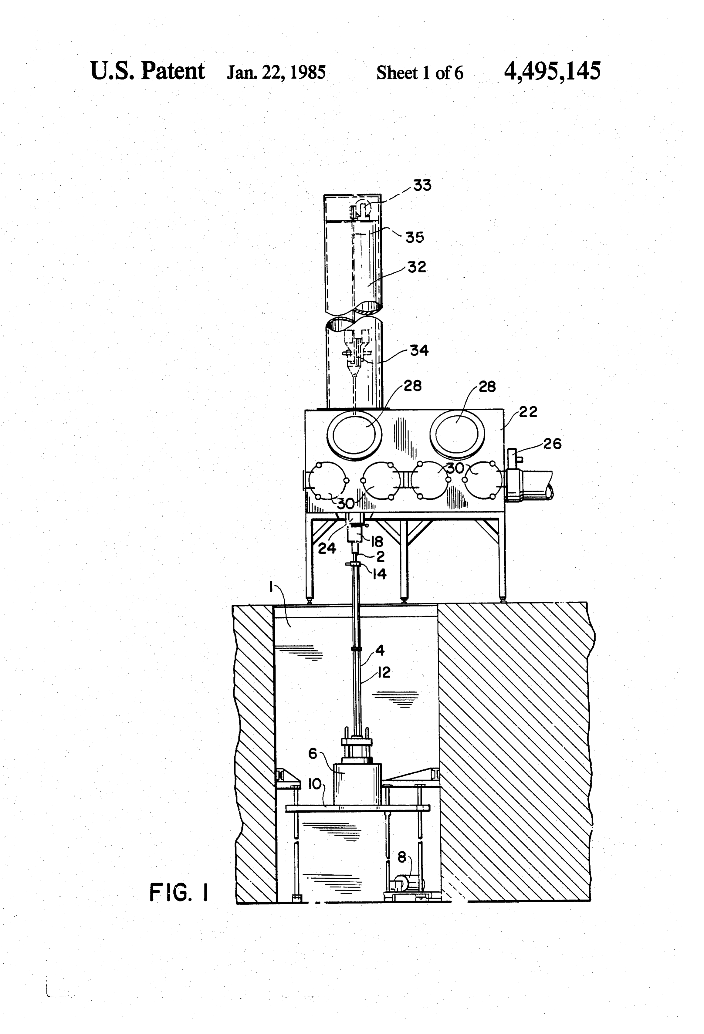
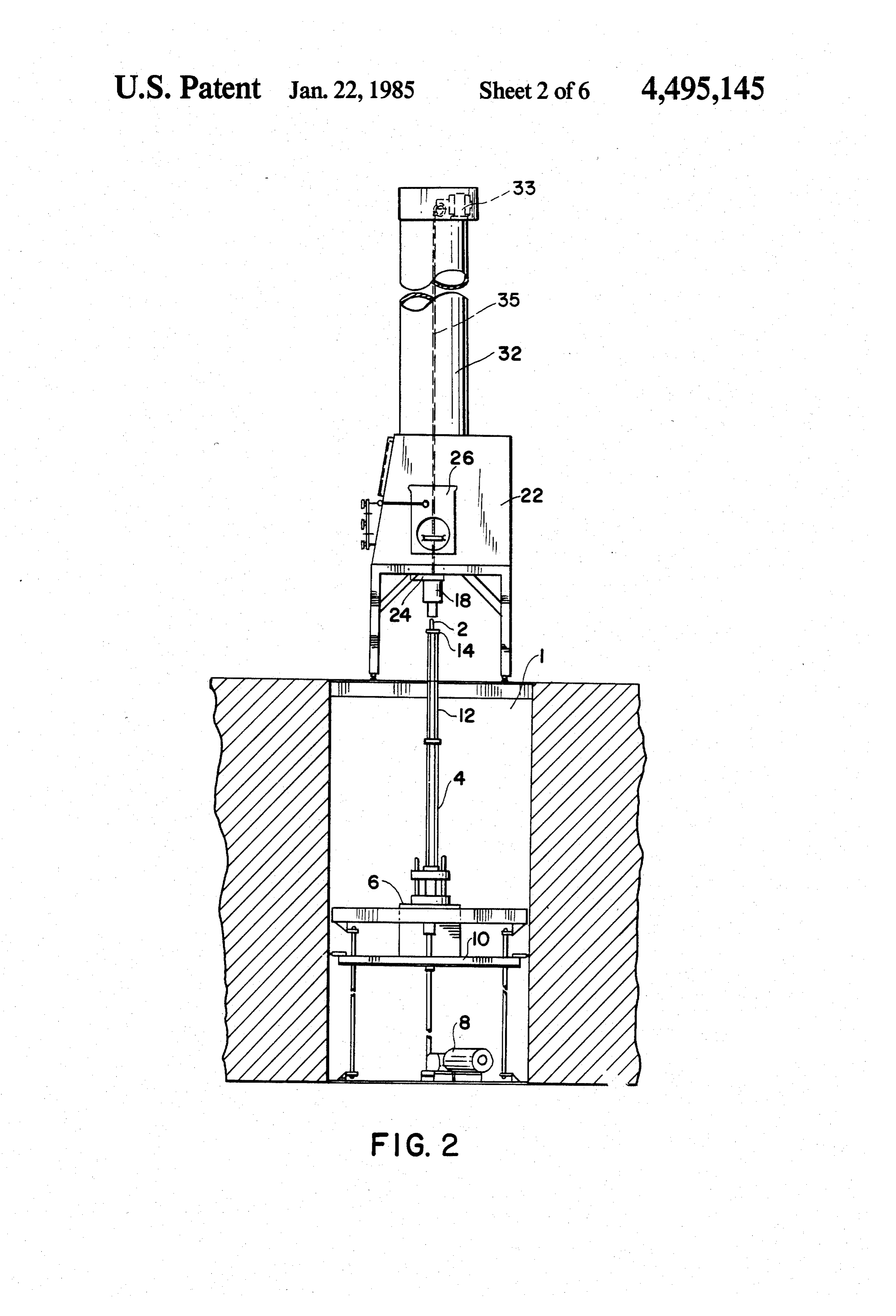
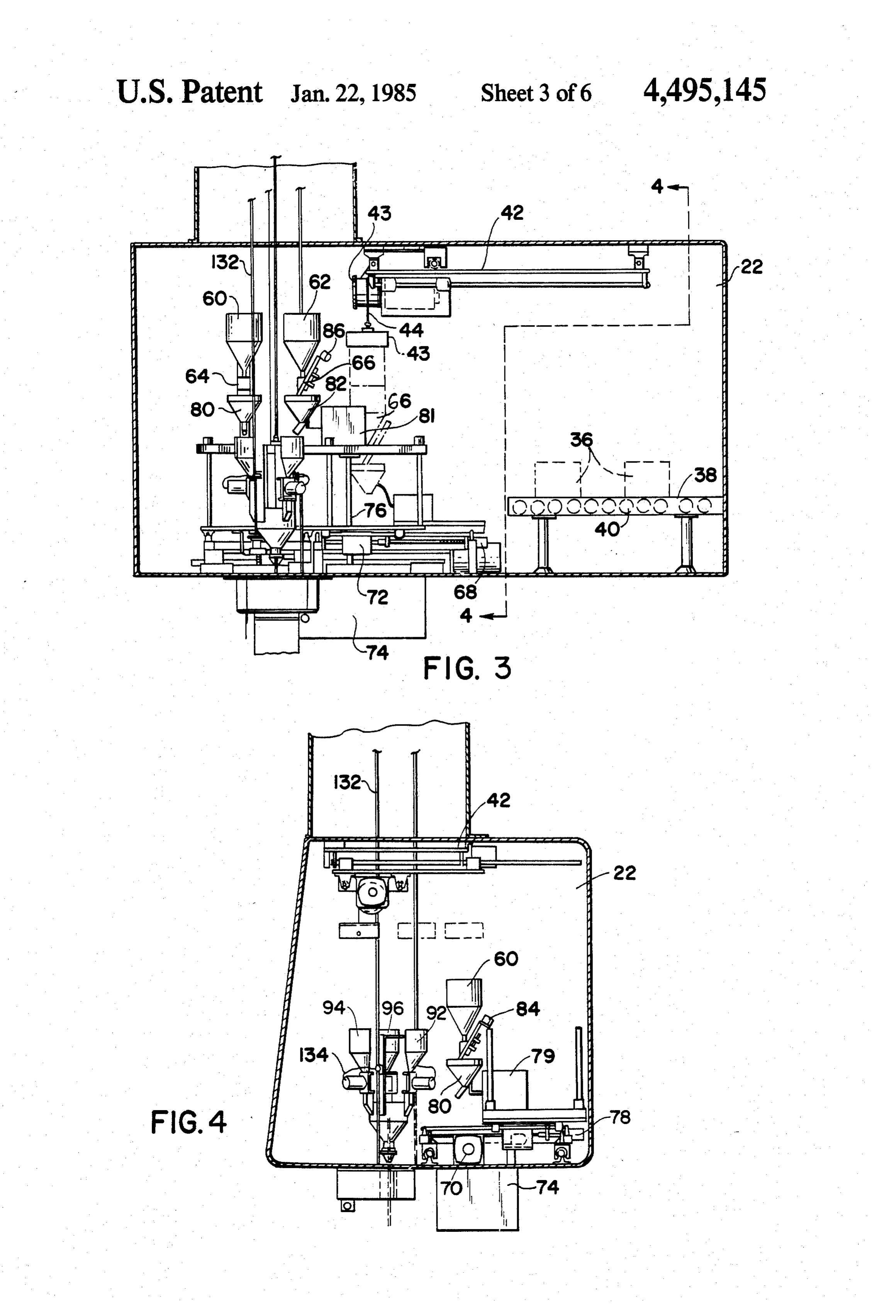
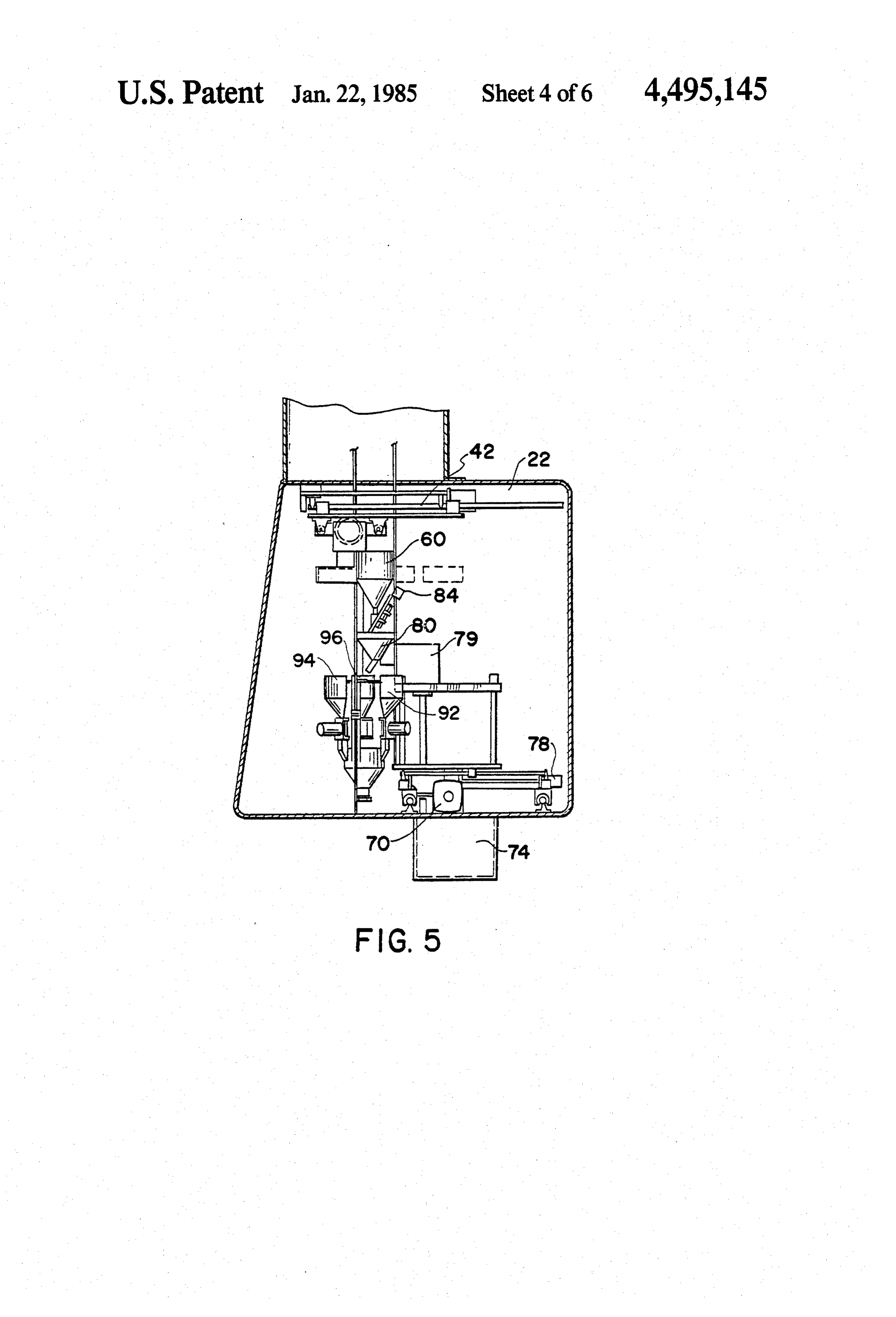
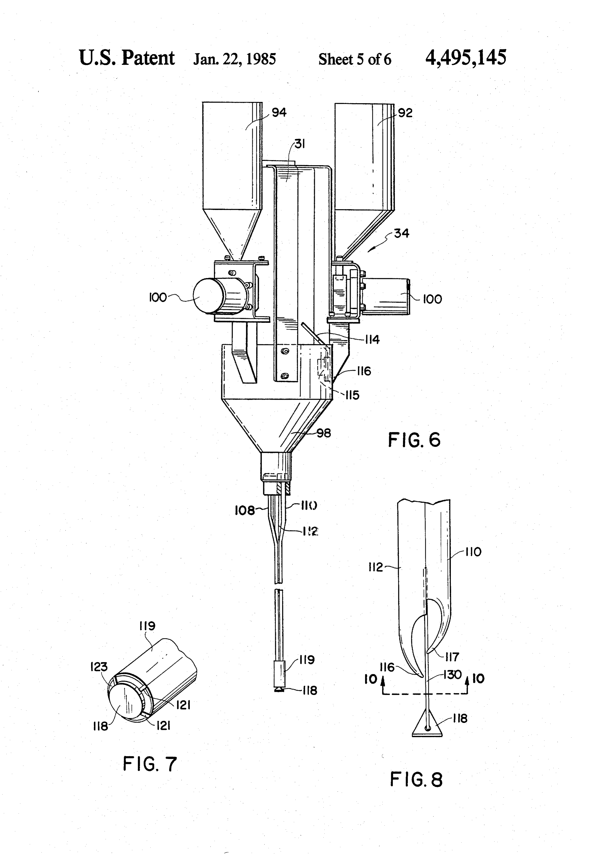
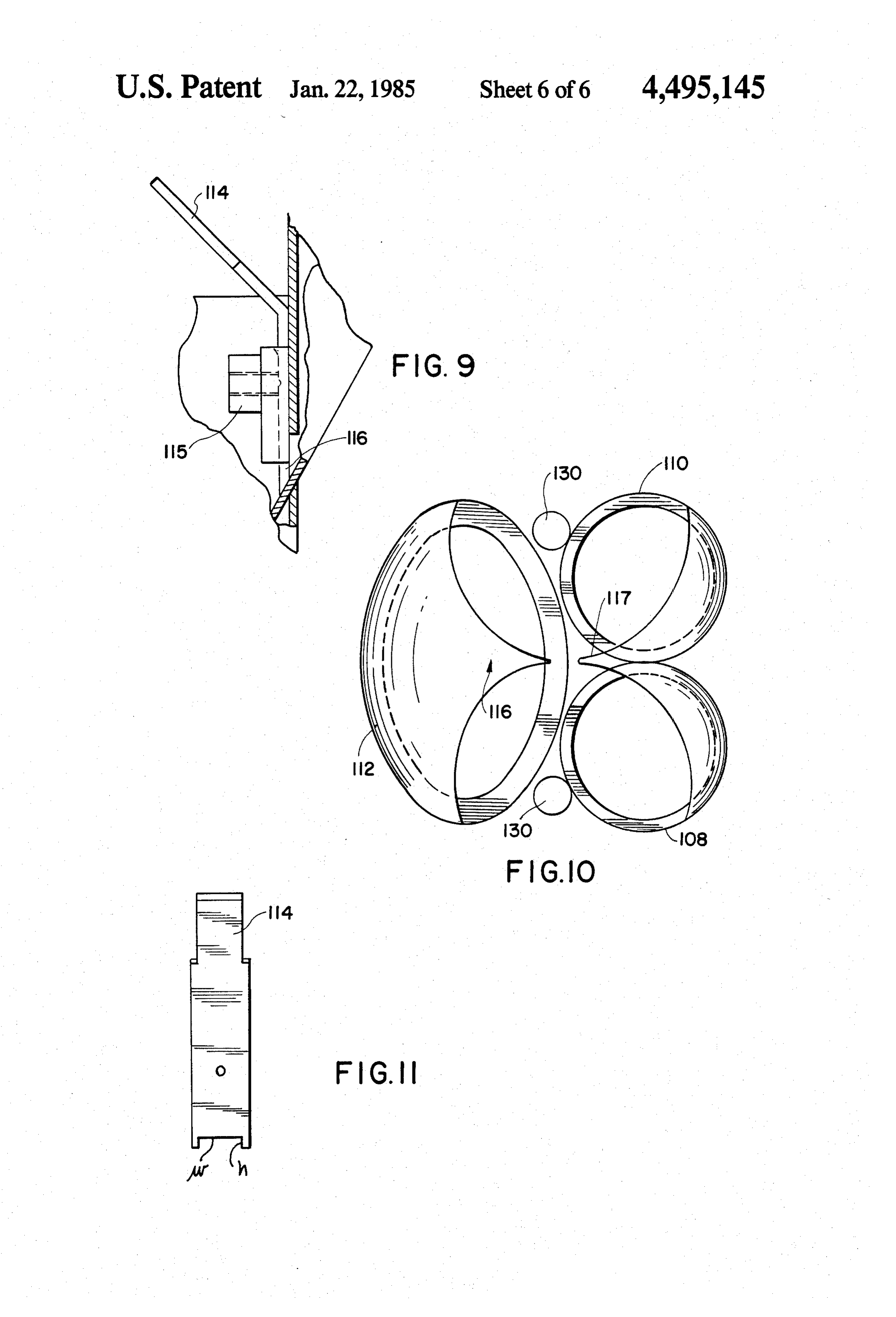
FIG. 8 shows an alternative embodiment of the lower
FIG. 9 shows a cross-sectional view of the regulator
FIG. 1 shows an elevated view of the system viewed 55 After entering the glove box through the vacuum from the front, valve 26, the fuel proceeds to the weighing station.
FIG. 2 shows an elevated view of the system viewed Referring to FIGS. 3, 4, and 5 shows the passage of the from the side.
Page 2drawing sheetscan →
Page 3drawing sheetscan →
Page 4drawing sheetscan →
Page 5drawing sheetscan →
Page 6drawing sheetscan →
Page 7drawing sheetscan →
Page 8scan →
FIG. 8 shows an alternative embodiment of the lower
SPHERECAL NUCLEAR FUEL LOADING PROBE end of the feeding probe.
FIG. 9 shows a cross-sectional view of the regulator
BACKGROUND OF THE INVENTION gate arrangement of the feeding probe. The present invention relates to the loading of fuel FIG. 10 shows the cross-section of lower end of the rods with spherical nuclear fuel. feeding probe of one embodiment viewed along 10-10 of FIG. 8.
In recent years it has been discovered that conven FIG. 11 shows the regulator gate. tional nuclear reaction fuel composed of fuel pellets encased in cladding tubes may lead to the splitting of DESCRIPTION OF THE PREFERRED the cladding tubes thereby releasing radioactive mate EMBODIMENT rial to the adjacent cooling water. This splitting is due The present invention is a loading probe for loading to an interaction between the pellet and cladding. One nuclear fuel rods with spherical nuclear fuel. The probe way of avoiding this problem is to limit the surface is part of an overall loading system described in copend interaction between the fuel and cladding. This may be 15 ing application Ser. No. 327,817 entitled “Spherical achieved by loading the fuel cladding tubes with nu Nuclear Fuel System' filed on Dec. 7, 1981 by the same clear fuel in the shape of spheres. If three different sizes inventor and assigned to the same assignee as the pres of spheres are used, than appropriate packing of the ent application and incorporated herein by reference. spheres into the rods will result in a sufficient density of The overall system is shown in FIGS. 1 and 3. FIG. 1 nuclear fuel to be properly used in a nuclear reactor. 20 shows the system viewed from the front. A fuel clad One method for loading a fuel rod is to simply drop ding rod 2 to be loaded with fuel is held vertically up the spheres into a vertical cladding tube while vibrating right by a fuel rod support clamp 4. Because of the the rod to assist in packing. However, this method is not length of the fuel rods 2, the rods 2 may be set in pit 1. satisfactory for several reasons. The distribution of the in the building floor. The support clamp 4 is fixed to a particles sizes freely falling from a height of 6 to 12 feet 25 vibrator 6 driven by vibrator motor 8. The vibrator 6 into a cladding tube does not lead to uniform distribu rests on a frame 10. The frame 10 is vertically adjustable tion. This method also leads to the trapping of air which to give the vibrator 6 a vertical travel of several feet. requires a longer time to evacuate at the sealing of the This allows the loading system to accomodate fuel clad tube. In addition, the vibrating packing is extended ding rods 2 of different lengths.
because of the random loading of the spheres. 30 The open upper end of the fuel cladding tube 2 is
Summary of the invention
attached to an adaptor 18 with an airtight connection.
The adaptor 18 is mounted to the glove box 22 via a
The invention is a loading probe for the loading of bellows arrangement so that the fuel tube 2 is flexibly spherical nuclear fuel into a fuel rod. The probe in 35 mounted to the glove box 22 allowing the fuel tube 2 to cludes a funnel means for receiving the spherical nu vibrate in response to the vibrator 6 while the tube is clear fuel, the funnel means maintaining a separation of being loaded. The adaptor 18 is connected to the glove the spherical fuel of different diameters; tubing means box 22 with a vacuum valve 24 so that the adaptor 18 corresponding to each of the spherical nuclear fuel and fuel tube 2 combination may be isolated from the diameters, the tubing means of sufficient length so that 40 glove
The box 22 forming an airtight combination.
glove box 22 is an enclosure capable of being one end of the tubing means extends about the length of made airtight which receives the nuclear fuel through the fuel rod in the load portion; valve means for releas the entrance vacuum valve 26. The glove box includes ably containing the fuel spheres within said funnel means, said valve means able to release the fuel spheres windows 28 and hinged glove box covers 30. Opening to the tubing means; gate means between the valve 45 the glove box covers 30 reveals gloves (not shown) mounted to the glovebox 22 which allows the operator means and the tubing means for regulating the rate of to accomplish manipulation within the glove box 22 flow of each the spherical fuel as it passes from the while still retaining the inert atmosphere within the funnel means through the valve means into the end of glove box 22. On the upper side and connected to the the tubing means away from the fuel rod; and deflector glove box 22 is the rod loading assembly cover 32. The means attached to the end of the tubing means within 50 rod loading assembly the fuel rod for mixing the fuel as it emerges from the allow the rod loadingcover 32 is of sufficient length to assembly 34 to rise high enough tubing means; so that it is free of the fuel cladding tube 2. FIG. 3 BRIEF DESCRIPTION OF THE DRAWINGS shows a side view of the glove box and fuel cladding tube assembly.
FIG. 1 shows an elevated view of the system viewed 55 After entering the glove box through the vacuum from the front, valve 26, the fuel proceeds to the weighing station.
FIG. 2 shows an elevated view of the system viewed Referring to FIGS. 3, 4, and 5 shows the passage of the from the side.
spherical nuclear fuel from the entrance vacuum valve
FIG. 3 shows the interior of the glovebox viewed 26 to the loading hoppers 60 and 62 of the weighing from the front. stations. The nuclear fuel spheres enter the glovebox 22 FIG. 4 shows the interior of the glovebox viewed through the entrance vacuum valve 26 in containers from the side with the fines weighing station in the load large enough to hold sufficient fuel for about six fuel position. tubes 2. The fuel containers 36 indicated by the dotted FIG. 5 shows the interior of the glovebox viewed lines, move along the rollers 40 of the transport con from the side with the fines weighing station in the 65 veyor 38, which may be powered or non-powered. dump position. After coming to rest on the conveyor 38, the fuel is FIG. 6 shows an elevated view of the feeding probe. lifted vertically upward by the overhead transport sys FIG. 7 shows the lower end of the feeding probe. tem 42. The over head transport system 42 is capable of 9 lifting the fuel container 36 from the transport conveyor releasably attached by conventional ball plunger means 38 and moving it from right to left and back and forth 115 to the hopper 98 so as to restrict the passage-way within the glove box 22. The overhead transport con 116 connecting the funnels 92 to the sections 102, 104 veyor 38 includes a rotating drum 43 around which is and 106 of the probe hopper 98. Referring to FIG. 11, wrapped a cord 44 for raising and lowering the spheres. the gate 114 includes an opening of height h and width The containers 36 are moved one at a time from the w. These dimensions are selected according to the size transport conveyor 38 to the loading hoppers 60 and 62 of nuclear fuel spheres and the desired rate of flow into of the weighing scales. In the preferred embodiment, the probe hopper 98. The rate of flow of each of the fuel three sizes of spheres are used, which are referred to spheres is determined so that upon emergence from the herein as fines, mediums and large. There are three 10 probe 34 within the fuel rod 2, the maximum random weighing stations, one corresponding to each of the ness of the three different size spheres is achieved. sphere sizes. However, only two of the weighing sta The probe hopper is connected to tubing 108, 110 and tions, the fines 64 and mediums 66 are shown for clarity. 112. Each of these tubes corresponds to one of the sec The mediums weighing station 66 is shown in FIG. 3 by tions of the probe hopper 98 which, in turn, corresponds the dotted figure in the load position for receiving fuel. 15 to one of the funnels 92, 94 and 96. In the particular The fuel container 36 are attached to the transport lid 43 embodiment shown in FIGS. 6 and 10, two of the tubes and moved by the overhead transport system 42 to each 108 and 110 are of the same circular cross-section. of the weighing stations where the fuel spheres are These tubes are used for the two smallest diameter fuel. deposited into the hoppers 60 and 62 of the scales. The largest fuel sphere is carried by the tube 112 of The mediums 65 and large 66 weighing stations are elliptical cross section.
mounted on one platform and move from side to side by The outer surface of lower end of each of the tubes the drive motor 68. In addition, the weighing stations 108, 110 and 112 is extended into scoops as shown in move up and down by the drive mechanism 72, the FIGS. 8 and 10. The scoop shaped extensions terminate glovebox 22 providing a recess 74 for the support shaft into 76 when the station is lowered. The fines weighing 25 centerpoints 116 and 117 toward the axis through the of the three tubed arrangement. The extensions station 64 noves front to back driven by the drive of tubes 108 and 110 for the two smaller tubes join motor 78 within the glove box 22 as well as side to side together to form one common point 117. These exten motion driven by motor 70. sions help in the mixing of the fuel spheres to provide a As noted above, the mediums 66 and large 65 weigh random distribution of packing of the fuel tube. To ing stations are mounted on one platform moved further enhance the randomness of distribution of the toward the glove box opening for loading. In addition, three different sized the weighing stations loading hoppers 61 and 62 are of packing of the fuelspheres and improve the uniformity rod 2, a cone shaped piece 118 is lowered to accommodate the fuel containers 36 which are moved to the weighing stations by the overhead fuel byfixed to the lower end of the fuel tubes 108, 110 and 112 transport 42. The fines weighing system 64 is mounted Thetwo 35 cylindrical rod members 130 as shown in FIG. 8.
cone 118 is fixed to the rods 130 by conventional independently of weighing stations 65 and 66 and moves le2S.
toward the back of the glove box 22, then to the right and down for loading. The fuel spheres containers 36 118Alternatively, as shown in FIGS. 6 and 7, the cone are picked up by the overhead transport system 42 and 110, and 112 by toa the may be fixed lower end of the fuel tubes 108, cylindrical collar 119. The collar positioned on top of the weighing station hoppers. The spheres are released into the loading hoppers 60, 61 and overlaps and is welded to the lower end of the fuel 62. Spheres of each size are dropped into the weighing tubes. The cone 18 is fixed to the other end of the scales hoppers 80 and 82 in incremental amounts by the collar 118 with the point of the cone 118 along the axis stepper motors 84 and 86. When predetermined of the collar and pointed toward the probe 34. The cone 118 is welded at several points 121 but leaving a gap 123 amounts of fuel spheres are received by the scale 45 between the cone 118 and collar 119 so that the fuel hoppers 80 and 82 as indicated by the weighing means spheres may emerge from the probe 34. 79 and 81 the flow ceases (Recall only two of the three weighing scales are shown in the Figures). These prede After the probe is loaded, the weighing stations are termined amounts of fuel spheres are sufficient to fill moved out of the way of the fuel feeding probe 90 and one fuel rod 2. These fuel spheres are then transferred to 50 the solenoid valves 100 are opened. The fuel spheres descend through the valve 100, the regulator gate 114 the hoppers 92, 94, and 96 of the feeding probe 34.
The feeding probe 34 is a device for depositing the and the tubing 108, 110 and 112. As the fuel reaches the three different sizes of spheres into the fuel rod 2 in a bottom of the fuel rod 2, the probe 90 is raised at a rate controlled manner so that the correct uniform density is so that the bottom of the fuel probe 90 remains just achieved in the rod 2. Referring to FIGS. 4 and 6, the 55 above the ascending fuel column. That is, the spheres probe 34 includes three funnels 92,94 and 96 into which are deposited on top of the fuel column such that the each of the three quantities of fuel is discharged from end of the probe remains between about 1 and 5 in the weighing scale hoppers 80, 81 and 82. In FIG. 6, above the ascending fuel column. The probe 34 is raised only two 92 and 94 of the three funnels are shown for and lowered by means 33 through a cable 35 attached to clarity. The funnels are spaced about 60° apart and are Bracket 31 of the probe 34. Copper tubes 132 guide the all identical except for the ability to accommodate dif feeding probe 90 up and down. The copper tubes 132 in ferent sized spherical fuel. The three funnels 92, 94 and combination with wires 134 provide the electrical 96 are connected to the probe hopper 98 via three sole contact to operate the solenoids 100. noid valves 100. There is one solenoid valve 100 for The vibrator 6 is in operation while the fuel rod 2 is each funnel. The probe hopper 98 is divided into three 65 being loaded. After the loading is completed and feed sections 102, 104 and 106. The fuel spheres, after being ing probe 90 is clear of the fuel rod 2, the rod is removed released by the solenoid valves 100, pass through a from the support clamp 4. A new fuel rod is placed in regulator gate 114 shown in FIG. 9. The gate 114 is the clamp 4 and process is started again.
Page 10scan →
ing one of said three sections of said hopper, each
EXAMPLE section of said hopper adacent to a corresponding
For fuel spheres having diameters 30 un, 200 um, gate means.
and 1200 um, the dimensions for the opening in the 4. The probe of claim 3 wherein said deflector means regulator gate is d=0.504 for all three gates and 5 includes:
h=0.020 in, 0.032 in and 0.1 in. (a) scoop shaped extensions of each of said tube ends I claim: toward said fuel rod, 1. A loading probe for loading spherical nuclear fuel (b) a tubular collar aligned along the axis of said three of three different diameters into a fuel rod comprising: tubes, one end of said collar surrounding scoop (a) funnel means for receiving said spherical nuclear 10 shaped extensions on said tube ends so that said fuel fuel, said funnel means maintaining a separation of emerges within said collar as it leaves said tubes, said spherical fuel of different diameters; and (b) tubing means corresponding to each of said spher (c) a cone axically aligned with the axis of said tubes ical nuclear fuel diameters, said tubing means of fixed to the other end of said collar so that a space sufficient length so that said tubing means extends 15 exists between said cone and the periphery of said about the length of said fuel rod in the load portion; other end of said collar, the point of said cone (c) valve means for releasably containing said fuel directed along the axis of said collar toward said spheres within said funnel means, said valve means scoops, said space sufficient to allow said fuel able meaSto release said fuel spheres to said tubing 20 spheres to pass and enter said fuel rod. (d) gate means between said valve means and said 5. The probe of claim 3 wherein said deflector means tubing means for regulating the rate of flow of each said spherical fuel as it passes from said funnel
(a) scoop shaped extensions of each of said tube ends means through said valve means into the end of toward said fuel rod, said tubing means away from said fuel rod; and 25 (b) a cone axially aligned with the axis of said tubes, (e) deflector means attached to said end of said tubing fixed to scoop end of said tubes by two rods, one means within said fuel rod for mixing said fuel as it end of said rods fixed to said tubes and the other emerges from said tubing means; end of said rods fixed to said cone, the point of said 2. The probe of claim 1 wherein said valve means are cone toward said tubes.
solenoid valves. 30 6. The probe of claim 1 wherein said gate means 3. The probe of claim 1 wherein said tubing means includes three V-shaped members releasably attached, includes: one member corresponding to each of said fuel sphere (a) three tubes aligned longitudinally each one tube diameters, each of said members including an opening corresponding to each of said diameters of nuclear whose dimensions are chosen so as to achieve sufficient fuel spheres, and 35 density of fuel in said fuel rod to operate in a nuclear (b) a hopper divided into three sections, one end of reactor.
each of said three tubes connected to a correspond
Provenance
- Collection
- Patents citing this work
- Pages
- 10
- Method
- pdftotext (the PDF's own text layer) + pdftoppm 300dpi page scans
- Patent office record
- patents.google.com →
- Source
- Google Patents citing-documents table
- Assignee
- Exxon Nuclear Company, Inc.
- Published
- 1985-01-22
- Transcribed from
- patentimages.storage.googleapis.com →