

patent · US4505264A
Electromagnetic wave concentrator
19 March 1985
Text
Page 1bibliographic recordscan →
United States Patent (19)
Tremblay
ELECTROMAGNETIC WAVE
CONCENTRATOR
Inventor: Réal Tremblay, Quebec, Canada Assignee: Universite Laval, Quebec, Canada
Int. Cl. ................................................ F24T 3/02 U.S. Cl. .................................... 126/439; 350/286;
4,078,548 3/1978 Kapany ............................... 26/440
4,344,417 8/1982 Malecek .............................. 126/440
FOREIGN PATENT DOCUMENTS
851313 7/1981 U.S.S.R................................ 350/286 Primary Examiner-Samuel Scott
Assistant Examiner-B. J. Bowman
Attorney, Agent, or Firm-Robic, Robic & Associates
Electromagnetic wave concentrator, especially a solar energy concentrator, in the form of a thin plate made up of a succession of identical light coupling modules each made up of two identical prisms made of transparent materials and having different indexes of refraction. The physical characteristics of the prisms are selected to cause continuous bending of the light beams, striking an incident face of the concentrator, toward a terminal edge surface of the concentrator plate.
17 Claims, 11 Drawing Figures
Drawings
Page 2drawing sheetscan →
Page 3drawing sheetscan →
Page 4drawing sheetscan →
Page 5drawing sheetscan →
Page 6drawing sheetscan →
Page 7scan →
ing surface and a surface opposed to the striking sur
ELECTROMAGNETIC WAVE CONCENTRATOR face, the surfaces intersecting terminal edge surfaces at the ends of the plate; wherein the plate is formed of a
The present invention relates to an improvement in succession, between the terminal edge surfaces, of iden electromagnetic wave concentrators, such as solar en 5 tical e.m. wave coupling modules abutting one another, ergy concentrators, for example. each constituted of a pair of prisms meeting on a com Various types of light or solar energy concentrators, mon surface and made of transparent materials of re of interest herein, have been proposed such as those fraction indexes n1 and n2; wherein the bases of the disclosed in Canadian Pat. Nos. 1,022,817 of 1977; prisms of index n1 are located in the e.m. wave striking 1,097,169 of 1981; 1,105,339 of 1981 and 1,123,292 of 10 surface and the bases of the prisms of index n2 are lo 1982 and U.S. Pat. Nos. 3,393,034 of 1968 (correspond cated in the opposed surface; wherein the successive ing to French Pat. No. 1,442,592); 4,074,704 of 1978; modules abut one another with a prisms of index n1 4,270,981 of 1981; 4,282,862 of 1981; 4,337,758 of 1982. immediately following a prism of index n2; wherein The most pertinent of these devices are those of U.S. n22 1 and n > n2; wherein each prism has the following Pats. Nos. 4,074,704 and 4,282,862 which use a planar 15 further parameters with respect to an angle 61 of wave array of prisms intended to refract light which is then incidence upon the striking surface concentrated by being deflected, behind the prisms, toward a common end of the concentrator. It is found 62262c that, possibly because of the light concentration taking place behind the light incidence prisms, the efficiency of 20 02c =sin(n2/n) such concentrators is low and they are bulky and cum bersome as well. 611262-6a
It is consequently a main object of the present inven 612 sinn sin (02-0) tion to provide a concentrator of electromagnetic and wherein 02 is the angle of wave incidence upon the waves capable of a high wave concentration while 25 common surface;
being in the form of a thin plate, that may be called a for total internal 62c is the critical value of the angle 62 wave reflection; 611 is the angle of multidielectric guiding plate. For convenience, such refraction of the waves incident upon the striking sur electromagnetic wave concentrators will, hereinafter, face; and 6a is the base angle of the prism of index n1 be referred to simply as light concentrators, although defined by the striking surface and the common surface, they apply to all other types of electromagnetic waves. 30
It is a further object of the present invention to pro of whereby waves incident upon the bases of the prisms index n1 is refracted in the said prisms, then totally vide a concentrator of the above type made of transpar reflected at said common surface and thereafter re ent materials and in a manner such as to cause deviation and guiding, between its flat faces, of light impinging fracted by the successive prisms, being thus bent toward one of the terminal edge surfaces to concentrate upon one on its faces and concentrated on one of its two 35 thereon.
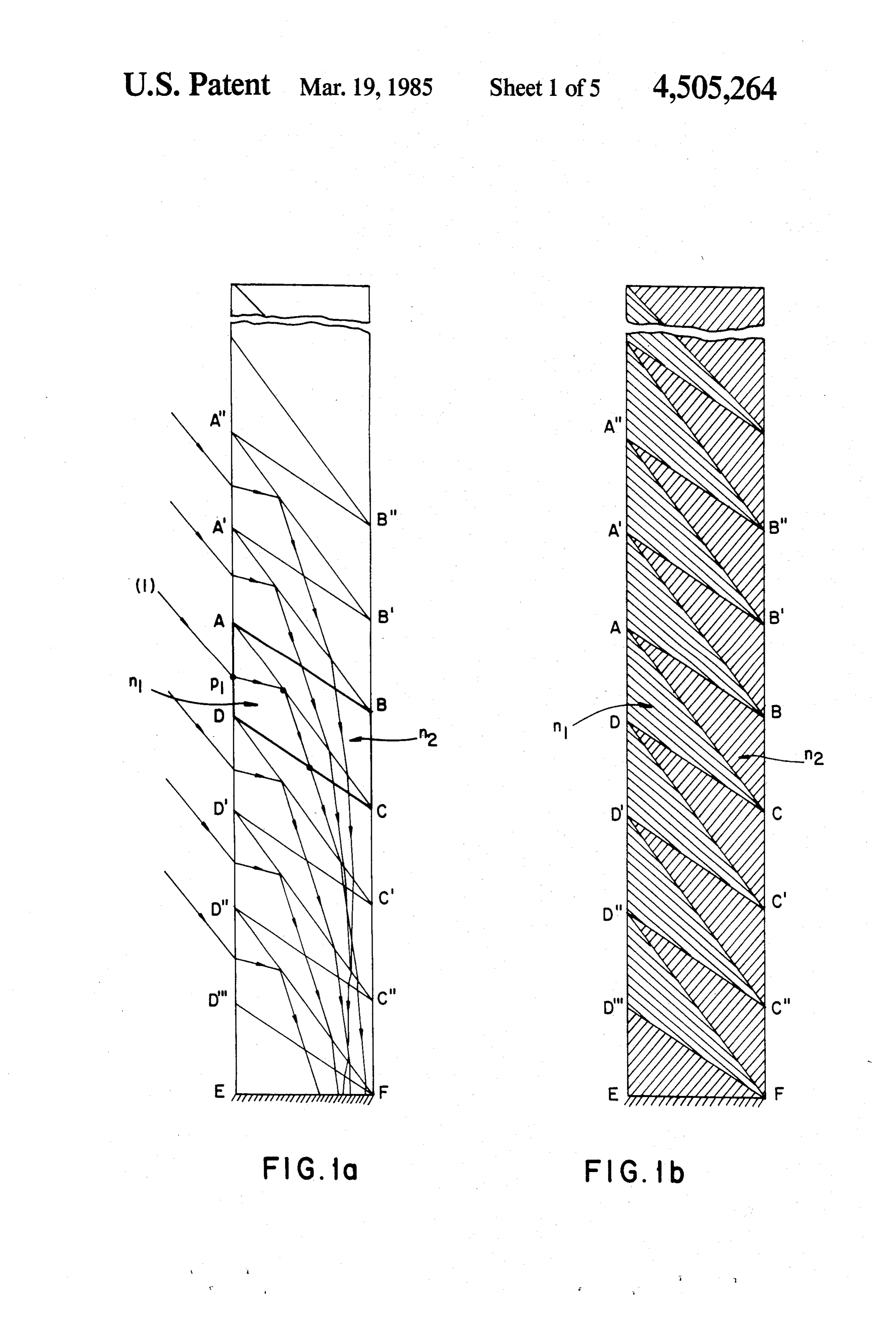
terminal edge surfaces. Embodiments of the invention will now be described Thus, the present invention proposes a concentrator capable of transferring a light flow, incident upon one with reference to the appended drawings wherein: of the faces of a thin plate, to a terminal edge surface of FIGS. 1a and 1b are diagrammatic side elevation the plate which is much smaller. The concentration presentofinvention;
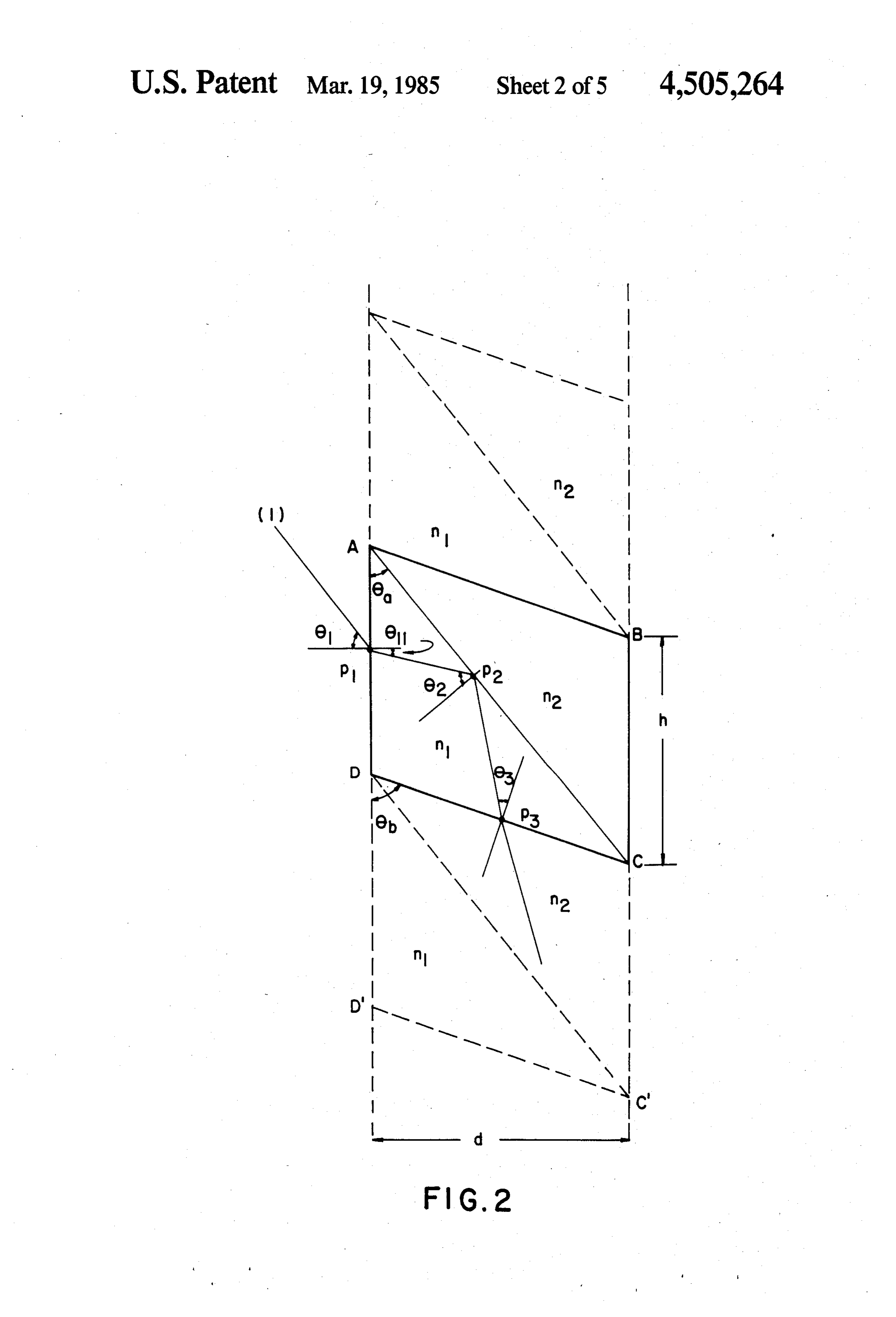
40 views a light concentrator made according to the factor is therefore proportional to the ratio of the sur face of the guiding plate over the terminal surface of the FIG. 2 is a diagrammatic side elevation view of a plate where the light energy is concentrated. It will portion of FIG. 1, on a larger scale;
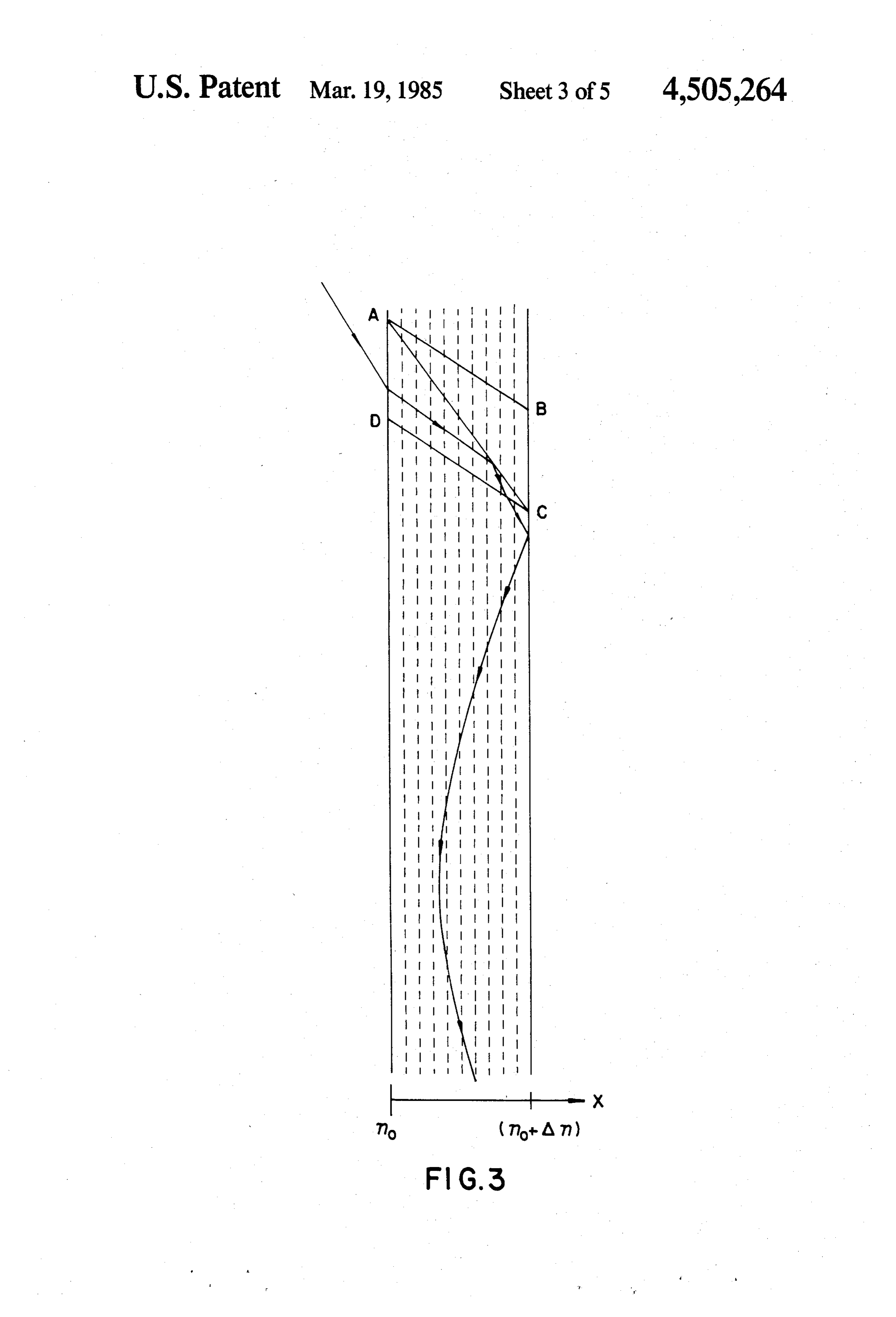
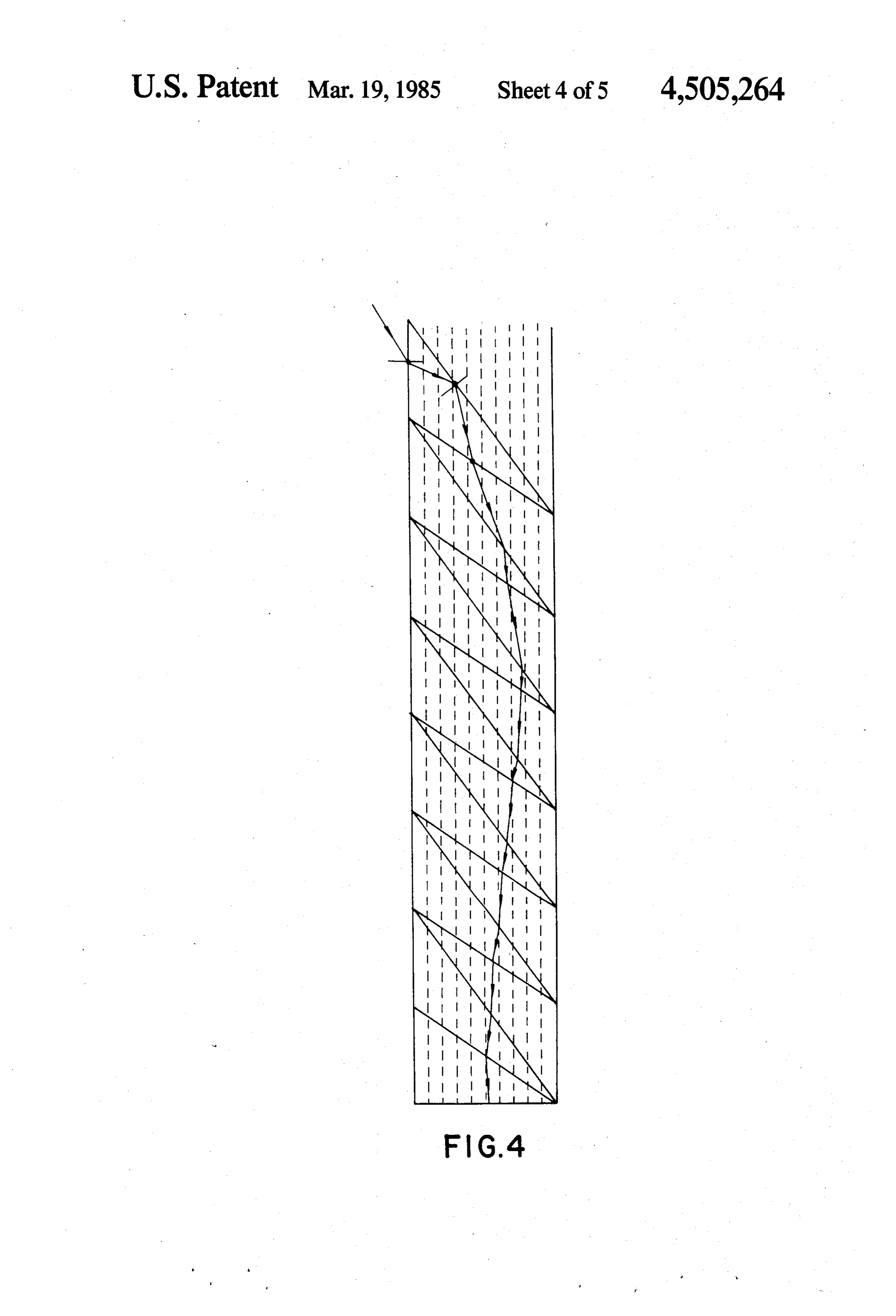
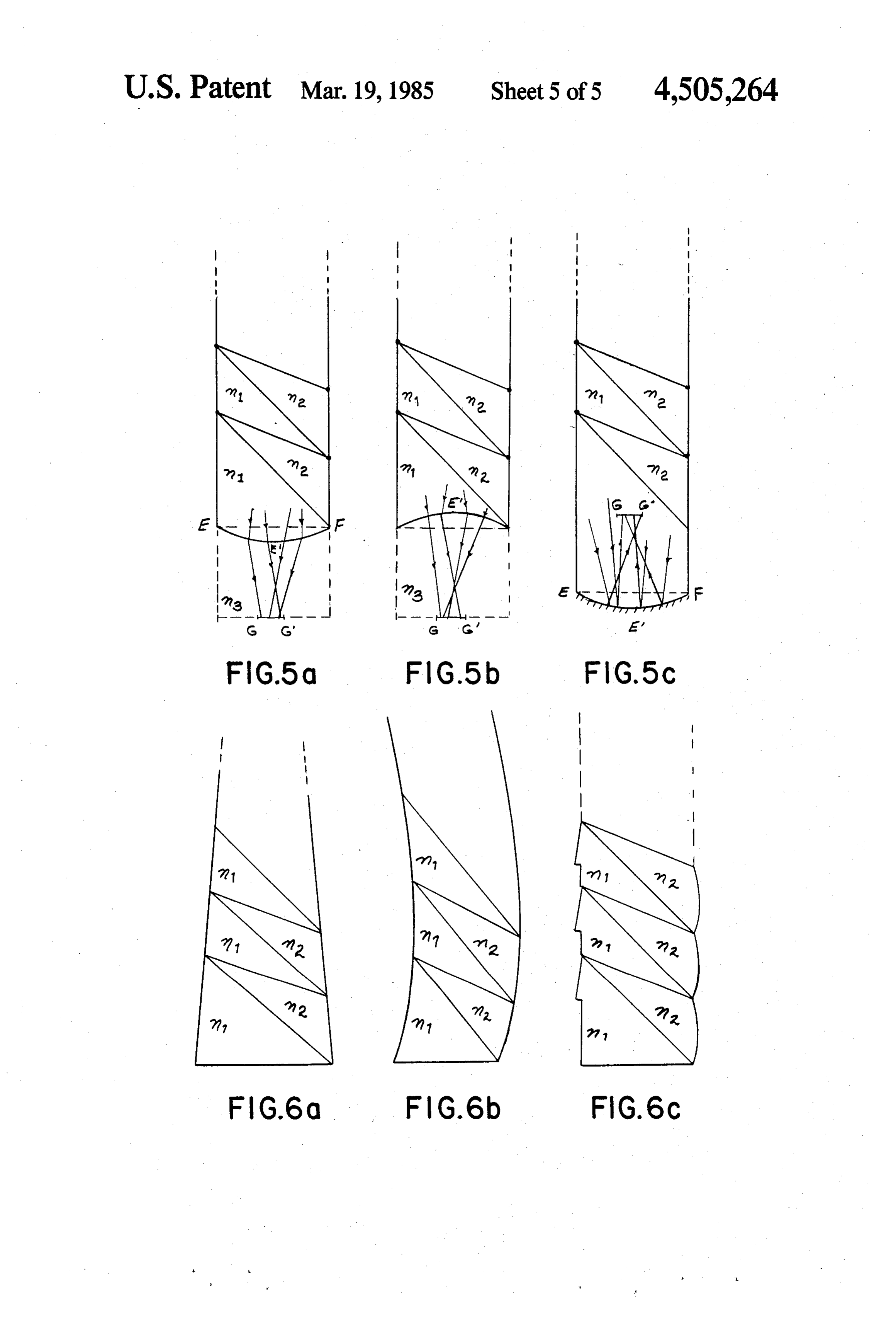
therefore be of interest to use plates of which the light FIGS. 3 and 4 are diagrammatic elevation views of impinging surfaces are as large as possible and of which 45 another embodiment of the invention; the thickness is as small as possible. FIGS. 5, a, b and c, are diagrammatic illustrations of concentrators having differently shaped concentration
By concentration factor is meant the ratio of the mean edges, energy density arriving at the edge surface of the plate and
Figs
where the light concentration takes place divided by the concentrators 6, a, b and c, are diagrammatic illustrations of flux of incident energy striking the concentrator. 50 having differently shaped light striking An additional object of the invention lies in the provi and opposed surfaces.
sion of a light concentrator in which the concentration With reference to FIG. 1, the element ABCD is a area is an integral part of the multidielectric guiding coupling module. Each coupling module is made up of plate itself, resulting in a concentration system which is two prisms of transparent dielectric materials having far less cumbersome than presently known systems, 55 different indexes of refraction: the prism ABC having The principle of operation of such a guiding plate an index n221 and the prism ACD has an index of calls for the following optical phenomena: refraction n1d n2. The light ray1 which strikes the face 1. A module capable of coupling light by total inter AD of the prism ACD at point p1 is refracted into the nal reflection at the intersection of two transparent medium of index n1. Thereafter, this ray meets the sepa dielectric media having different indexes of refraction; 60 ration surface AC between the two media of different 2. a manner of guiding the light by the use of pris indexes n1 and n2 at point p2 and it is totally reflected matic elements alternatingly distributed along the guid since n > n2. The ray then leaves the coupling module ing plate; at point p3. By arranging several identical coupling 3. the coupling module is also an element of the peri modules in succession and in parallel, the faces A"A", odic network that serves as a guide. 65 A'A, AD, DD", etc. . . define the inlet or striking sur Accordingly, the invention is herein broadly claimed face of the guiding plate whereas the faces B'B', BB, as an electromagnetic wave concentrator in the form of BC, CC, etc. . . define the other or opposed surface of a substantially flat thin plate having an e.m. wave strik the guiding plate.
Page 8scan →
The ray which leaves the coupling module ABCD at the striking surface AD; and 6a is the base angle of the point p3 is refracted successively in the coupling mod prism of index n1 defined by the striking surface AD and ules DCC'D', D'C'C'D' etc... and is thus guided along the common surface or separating surface AC. the plate to finally reach the terminal edge surface EF All rays striking the inlet face AD of a coupling mod of the plate through a terminal prism D'EF. The cou pling modules being identical, all rays parallel to the ray ule with angles of incidence 01 greater than 61 minimum 1 will have the same trajectory as that of the said ray 1, dence 62 the impinge separation surface AC with angles of inci greater than the aforesaid critical angle and are these trajectories being simply moved upwards or therefore all completely reflected. downwards depending on the coupling module on For angles of incidence, at point p1, that are smaller which they impinge. Most of these rays end up on the 10 than the minimum angle of incidence 01 min, a portion terminal edge EF of the guiding plate of which the surface is far smaller than the striking surface of the only of the light is reflected at point p2. The guiding plate is therefore, so to speak, limited to plate. There follows a concentration effect of the light energy over a surface which is an integral part of the guiding light rays impinging one of its faces with a very plate which serves to collect the light energy. 15 minimum angle of incidence. The latter becomes a fea If one or the two dielectric media are liquids, a con ture of the coupling module and thus of the guiding fining wall or walls of materials transparent to light and plate. This minimum angle of incidence is a function of of a refraction index similar to the refraction index of the manner with which the guiding plate is constructed the liquid retained by this wall or walls must of course and of the materials used for constructing it. It is possi be provided to contain the liquid. In the case where 20 ble to change the minimum angle of incidence by both media are liquids, the separation surface between changing one of several of the parameters n, n2 and 6a, these liquids must have a refraction index such that the that is, by changing the nature of the materials or the losses by reflexion at the surfaces of separation of the configuration of the coupling prism. wall with the median and n2 are minimized as much as The angle 0b, which is the supplement of the apex possible. 25 angle at point D of the prism ACD is selected so as to Thus, prismatic elements A'B'B'A', A'B'BA, be greater to or equal to the angle of refraction at point ABCD, DCC'D', D'C'C'D', etc. . . are identical cou p1 when the angle of incidence at point p is 61 min. pling modules which make use of the phenomenon of Expressed otherwise, the base angle ADC is selected total internal reflection. Light coupled to the plate is according to the following relation: guided between the bounding surfaces of the plate by 30 the prismatic elements, the latter being themselves cou 8b290-01 pling elements or, in other words, each of the coupling elements is at the same time an element of the periodic for a minimum value of 6 suitable to ensure full reflec network which serves as a guide. tion of light within a module ABCD. FIG. 2 is a transverse cross-section of a coupling 35 The above selection of 6b is desired due to the fact module from which can be determined the relations that when the point p is located near the apex D, it between the various parameters of a guiding plate. cannot be avoided that part of the light rays refracted at It is assumed that the two dielectric media have in dexes n1 and n2 with n > n2. The prism ABC is a me point p1 meet the separating face DC, between two adjoining modules, before having met the separation or dium of index n1 and the prism ACD is one of index n2. common surface AC of a module. AC is the separation surface or common surface of the After having been reflected at point p2, the ray 1 two media. The apex angle A of the prism ACD is 0. meets the separation surface DC at point p3, surface DC A light ray 1 incident at point p1 is refracted into the separating two successive coupling modules. This light medium of index n1 and thereafter strikes the common surface AC at point p2. The light ray is completely 45 ray passes from a medium of index n1 to a medium of reflected at point p2 provided that the angle of inci index n2 with n1 greater than n2, but the angle of inci dence 02 at that point be equal to or greater than the dence 03 at this point being smaller than the critical critical angle 02c=sin (n2/n) at that point. This im angle, there will be refraction of most of the energy of plies that the angle of refraction 01 at point p1 be equal the ray toward the medium of index n2. to or greater than (62-6) and that the angle of inci 50 The rays leaving the separation surface DC at a point dence 01 at point p1 be equal to or greater than sin p3, close to apex C, meet the surface CC and are there n1sin (02c - 6a). A minimum angle of incidence 01 min in most cases totally reflected before being successively at point p1 thus exists for which there is total reflection deviated by the other coupling modules. at point p2. As FIG. 1 shows, the ray 1 is thereafter successively The above relations are algebraically expressed as 55 deviated by the other coupling modules and thus guided follows: toward the terminal edge surface EF of the plate. The deviation of the ray caused by each of the coupling and 02282 guiding modules is directly related to the difference in 92=sin(n2/n) index between the two dielectric media (Ann - n2). 60 The height h of each coupling module is a function of 82.82c - 6a the thickness d of the plate. By increasing the thickness d, the height h of each module is increased in the same 012 sin(n sin (02-0a)) proportion.
There are losses of energy associated with the light and wherein, as mentioned above, 02 is the angle of light 65 transmission within the plate, these losses are produced incidence upon the common surface AC; 02c is the criti (a) by partial reflection at each of the surfaces that cal value of angle 62 for total internal light reflection; separate media having different indexes; 011 is the angle of refraction of the light incident upon (b) by absorption within the dielectric materials.
Page 9scan →
However, by appropriately selecting the various opti centration factor over the terminal edge surface EF and cal and geometrical parameters, (and/or by coating the without increasing the ratio H/d. Furthermore, this surfaces separating different media with anti-reflexion solution is not interesting as it implies a larger quantity layers) it is possible to design a system wherein the of materials of indexes n1 and n2 per unit of surface losses by reflection are relatively small and which per necessary to couple the energy in the guiding plate. mit propagation on an extended length and a concentra This is therefore not the solution for increasing the tion factor having much interest in several applications. distance that the rays could travel between the faces of A model has been experimentally tried in laboratory. the plate.
The following parameters were used: Another solution would reside in the construction of 10 a guiding plate with materials having a variable refrac = 1,5 (acrylic) n2 1,33 (water) tion index. Following research work in integrated op d = 6.0 cm 61 min 50 tics, there exists presently the possibility of making transparent dielectric media with a variable index (for
The behavior of the rays is indeed that expected from 15 instance SELFOCROD LENS). FIG.3 of the drawing the theory of geometrical optics. shows a plate of which the index varies according to the The table 1 that follows gives the theoritical results relation n = no(1+(Ax2/2), where nois the index at x=o obtained for a plate having 7 coupling modules and of and A is a constant, X being the distance from the base which the optical and geometrical parameters are: AD to the point under consideration. Thus, x =o ex n = 1.5, n2 = 1.33, 61 mise 50', 6=31.7, 6b =55.3. The 20 presses the situation where the point at which the index ratio H/d between the height H of the plate and its is being determined is located on the face AD. Such a thickness d is 7.2. plate would deviate a ray between its walls along a TABLE 1. trajectory shown in FIG. 3.
Here is a solution suitable to solve the problem of 25 energy being lost due to the rays escaping from the guiding system by refraction into the air. It lies in pro 60 2,6 75 viding a coupling module made, as above, of two prisms 65 2,0 72 wherein the index of refraction would vary continu ously between the bounding faces of each prism. Thus,
The angle of incidence 61 is given in the first column. for onewould 30 prism, the index would be n1 at the inlet face AD
The concentration factor F* obtained on the terminal and (n1--an) at vary continuously until the index be the other face AC. For the other prism, it surface EF with respect to a unit concentration incident would vary from n2 to (n2+A) when moving from upon the striking surface of the plate is given in the faces AC to BC.
second column. 26E is the percentage of the energy that Such a system would have the following particular penetrates into the plate and that is available on the 35 features.
terminal surface EF of the plate. No account has been made of the losses due to absorption in the dielectric of (a) the an index difference (n-n2) remains at each point surface of separation AC between media 1 and 2 materials, losses that are small in the case under consid eration. so that the coupling modules can still, by total inner see definitin of F on page 2, above. 40 reflection, couple the energy between the faces of the The maximum number of coupling modules that may plate;
be placed one next to the other is mainly limited by the (b) the rays, as they move between the faces of the fact that the rays, coupled by the coupling modules plate, are again subjected to deviations due to the re located furthest from the terminal edge surface EF of fraction as they move from one medium to the other, the plate, may lose a large part of their energy by refrac 45 the totality of these deviations tending to cause the rays tion into the air. This refraction into the air is due to the to rotate clockwise (FIG. 1); fact that, after having been deviated several times by the (c) the rays in moving along between the faces of the guiding modules, these rays may reach one of the faces plate are subjected to the effect of a medium having a of the plate with an angle of incidence such that they variable index, whether they be in the medium 1 or the may escape from the plate. It follows that this phenome 50 medium 2, this effect tending to cause deviation of the non may limit the ratio height of the plate over thick rays counterclockwise (FIG. 3);
ness of the terminal edge of the plate and thus likewise (d) the combined effects (b) and (c) cancel one an limit the concentration factor. other thereby allowing the rays to cover much greater For the applications being considered, light guide, distances for a given thickness d of the plate (FIG. 4). flat concentration solar collector, the proposed system 55 In such systems, the number of successive coupling is that much more of interest that the distance travelled modules that can be placed one against the other is by the rays guided between the faces of the plate is limited by:
greater for a given thickness of the plate. (a) small losses due to partial reflection of rays at each This maximum height H is a function of the optical of the surfaces that separate media having different parameters of the medium and of the thickness of the 60 indexes;
plate. (b) the absorption in the dielectric materials, For a given number of coupling modules, a solution (c) the diffusion due to the dielectric materials not for increasing the height H of the plate is to increase its being homogenous.
thickness d. The height h of a coupling module being Instead of varying continuously, the index could be directly related to the thickness of the plate, an increase 65 made to vary by steps by superposing a few layers of in the thickness d increases the height H in the same media having different indexes.
proportions. In such a case, the quantity of light cou With reference to the particular embodiments of pled in the plate is increased without increasing in con FIG. 5, the terminal edge concentration surface may be 10 of a shape other than the straight edge EF of FIGS. 1, said successive modules abut one another with the ex 3 and 4. ternal surface of a prism of index n1 abutting the exter It could have a shape such that a very large portion of nal surface of a prism of index n2; wherein n22 1 and the rays guided between the surfaces of the guiding n > n2; wherein each prism has the following further plate be refracted, at the separation surface EEF, in a 5 parameters wwith respect to an angle 61 of wave inci direction such that they would then concentrate in a dence upon said striking surface
Zone of which the section GG' would be smaller than the edge surface EF corresponding to the thickness of the plate. This would automatically increase the con centration factor Fc. The shape of the edge surface 10 02=sin(n2/n)
EEF will be a function of the orientation, of the distri bution and of the intensity of each ray at the terminal 811282c-6a edge of the plate as well as a function of the indexes of 82 sin (ni sin (02-0a)) the dielectric media on either side of the separation edge surface EEF. 15
With reference to FIGS. 5, (a) to (c), here are some and wherein 62 is the angle of wave incidence upon said non-limitative examples of the shape that the edge sur common surface; 62c is a critical value of the angle 62 for face of the plate could take if most of the rays were total inner wave reflection; 611 is the angle of refraction nearly parallel to the confining surfaces of the guiding of the waves incident upon said striking surface; and 6a plate. 20 is the base angle of the prism of index n1 defined by said If the medium of index n1 is such that n1&n3, the edge striking surface and said common surface, surface EEF should be convex and if the medium of whereby waves incident upon the bases of said prisms index n3 is such that n <n3, the edge surface should of index n are refracted in the said prisms of index then be concave. n1, then totally reflected at the said common sur Another way of increasing the concentration factor, 25 face and thereafter refracted by said successive while retaining the energy within the medium of index modules, being thus bent toward one of said termi n1, would be to give the edge surface EEF a convex nal edge surfaces to concentrate thereon. shape and to coat surface EEF with a reflecting mate 2. A concentrator as claimed in claim 1, wherein the rial. The rays reflected by the coated surface would supplemental angle 65 to the other base angle of each concentrate in an area of the medium of index n1 of 30 prism of base angle 6a is selected according to the fol which the section GG' would be smaller than the edge lowing relation:
surface EF. (FIG. 5c)
With reference to FIG. 6, it is not absolutely neces 8,290-61 sary that the e.m. wave striking surface and the opposed surface of the guiding plate be parallel as in FIG. 1. 35 for a minimum value of 61 suitable to ensure full reflec They could be tapered, as in FIG. 6(a) or curved as in tion of light within said modules. FIG. 6(b). They could also be both, or one only, discon 3. A concentrator as claimed in claim 1, wherein at tinuous, as in FIG. 6(c). In the latter case, the base of least one of said prism of each module is a liquid. each prism of index n1 is sawtooth in configuration 4. A concentrator as claimed in claim 1, wherein said and/or the base of each prism of index n2 is concave. 40 prisms are made of a material having a variable index ny To resume, the present invention proposes a multidie of refraction.
lectric guiding plate which can serve as polychromatic 5. A concentrator as claimed in claim 2, wherein said guide and of which the essentially planar surface has a prisms are made of a material having a variable index ny minimum bulk in the case where it is applied to a flat of refraction.
e.m. wave concentrating collector. This plate could also 45 6. A concentrator as claimed in claim 4, wherein said be integrated into a modular system which would use variable index ny is, at a predetermined point in said several plates so arranged as to increase the energy prisms, equal to concentration factor in a predetermined region.
In applications where the results given in Table 1 no (1+(Ax/2)) above would be satisfactory, materials commonly found 50 in construction could be used.
I claim: wherein no is the value of the index at the base of the 1. An electromagnetic wave concentrator in the form ing prism being considered; x is the distance from the strik of a substantially flat thin plate having an electromag Stant. surface to said predetermined point and A is a con netic wave striking surface, a surface opposed to said 55 7. A concentrator as claimed in claim 5, wherein said striking surface, and a pair of terminal edge surfaces variable index ny is, at a predetermined point in said intersected by said striking and opposite surfaces, wherein said plate is formed of a succession, between prisms, equal to said terminal edge surfaces, of electromagnetic wave no (1+(Ax/2)) coupling modules abutting one another, so as to form a flat plate-like structure, each of said modules consisting of a pair of prisms meeting on a common surface and wherein no is the value of the index at the base of the prism being considered; x is the distance from said strik made of transparent materials of refraction indexes n and n2, said prism each having a base and an external ing surface to said predetermined point and A is a con surface joining said base to the common surface 65 Stant. 8. A concentrator as claimed in claim 1, wherein the wherein the bases of the prisms of index n1 are located in said wave striking surface and the bases of the prisms prism
Water.
of index n1 is acrylic and the prism of index n2 is of index n2 are located in said opposed surface; wherein
Page 11scan →
9. A concentrator as claimed in claim 2, wherein the 13. A concentrator as claimed in claim 1, wherein the prism of index n1 is acrylic and the prism of index n2 is base of each prism of index n1 is saw-tooth in configura Water. tion and/or the base of each prism of index n2 in convex. 14. A concentrator as claimed in claim 1, wherein said 10. A concentrator as claimed in claim 1, wherein said 5 one terminal edge surface is straight. wave striking and opposed surfaces are parallel. 15. A concentrator as claimed in claim 1, wherein said 11. A concentrator as claimed in claim 1, wherein said one terminal edge surface is convex. wave striking and opposed surfaces are tapered be- 16. A concentrator as claimed in claim 15, wherein said convex surface is coated with a reflection material.
tween said terminal edge surfaces. 10 17. A concentrator as claimed in claim 1, wherein said 12. A concentrator as claimed in claim 11, wherein one terminal edge surface is concave. said wave striking and opposed surfaces are curved. sk x 2k xk k
Page 12scan →
United states patent and trademark office
Certificate of correction
INVENTOR(S) : Real Tremblay
It is Certified that error appears in the above-identified patent and that said Letters Patent is hereby Corrected as shown below:
In the specification
Column 5, line 40: "definitin" should read --definition-- and "page 2" should read --Column l, line 47-;
line 68: "increasing in" should read --increasing the--; Column 6, line l6: "n = n ( l+(Ax/2)" should read line l7: "X" should read --x-- line 32: "n +xn" should read -n. +An-;
Column 8, line 5: "with" should read --with--; line 8: e2 22 should read Z signed and sealed this
Seal
Fifth Day of November 1985
Attest:
Donald.j. quigg
Attesting Officer Commissioner of Patents and Trademarks
Provenance
- Collection
- Patents citing this work
- Pages
- 12
- Method
- pdftotext (the PDF's own text layer) + pdftoppm 300dpi page scans
- Patent office record
- patents.google.com →
- Source
- Google Patents citing-documents table
- Assignee
- Universite Laval
- Published
- 1985-03-19
- Transcribed from
- patentimages.storage.googleapis.com →