

patent · US4512865A
Electrolytic sterilizer for contact lenses
23 April 1985
Text
Page 1bibliographic recordscan →
United States Patent (19)
Yamauchi
54 ELECTROLYTIC STERILIZER FOR
CONTACT LENSES
75 Inventor: Masakatu Yamauchi, Kani, Japan 73 Assignees: Tanica Electric Co., Ltd., Tajimi;
Tomei Sangyo Kabushiki Kaisha,
Nagoya, both of Japan
(51) Int. Cl. ................................................ C25B 9/00 52 U.S. C. ..................................... 204/271; 204/275 (58) Field of Search ........................ 204/242, 275,271
4,202,740 5/1980 Stoner et al. . ... 204/271 4,289,599 9/1981 Fushihara ............................ 204/27
4,316,787 2/1982 Themy ................................ 204/27 Primary Examiner-R. L. Andrews
Attorney, Agent, or Firm-Oblon, Fisher, Spivak,
McClelland & Maier
An electrolytic sterilizer for contact lenses comprising a main body accommodating a power source unit and a sterilizing container detachably mountable on the main body and having electrodes electrically connectable, through container-side contacts and main body-side contacts, to said power source for electrolysis, wherein the main body has a groove for a waste solution, and the main body-side contacts are located outside of the groove.
2 Claims, 3 Drawing Figures
Drawings
Page 2drawing sheetscan →
Page 3scan →
lenses kept in a container filled with a physiological
ELECTROLYTICSTERILIZER FOR CONTACT Sodium chloride solution are sterilized and disinfected LENSES as they are kept in the container. The sterilization and disinfection is accomplished by electrolyzing the physi
BACKGROUND OF THE INVENTION 5 ological sodium chloride solution to form an effective 1. Field of the Invention amount of sodium hypochlorite as a disinfectant. An The present invention relates to an electrolytic steril electrolytic sterilizer for contact lenses of this type izer for contact lenses comprising a main body accom comprises a main body accommodating a power source modating a power source unit and a sterilizing container unit, a sterilizing container detachably mountable on the detachably mountable on the main body. More particu 10 main body, and a structure for electric connection, larly, the present invention relates to a specific structure which is provided at the joint portion. The structure for for the electrode connection in such an electrolytic electric connection in this type of sterilizer comprises sterilizer. base body-side contacts formed of a material such as 2. Description of the Prior Art conductive rubber in a recess of the main body designed Conventional hydrated contact lenses composed 15 to receive the sterilizing container. If the physiological principally of a hydrophilic monomer such as 2-hydrox sodium chloride solution to be used for sterilization or yethyl methacrylate normally contain more than about the sodium hypochlorite solution obtained by the elec 30% by weight of water. As a result, the hydrated trolysis is deposited or dropped in a small amount and if contact lenses are likely to provide by themselves a the sterilizing container is connected for sterilization, favorable environment for the multiplication of various 20 electrolysis takes place between the body side contacts, detrimental bacteria. Furthermore, it is very dangerous whereby the electrolysis in the sterilizing container will to wear bacteria-infected contact lenses on the eyes be disturbed or impaired and a disinfectant solution without treating them in any way, since this practice having an adequate concentration will not be formed. may lead to serious damage to the eye tissue. For this Accordingly, if the contact lenses are washed and steril reason, it is essential to sterilize such hydrated contact 25 ized with such a disinfectant solution, no adequate ef lenses periodically.
For example, the most common method for steriliz fectiveness will be obtained, and if such contact lenses still infected with bacteria are worn, there will be a ing the hydrated contact lenses is a method wherein the possible lenses are boiled for a predetermined time. This method additionaldanger of hurting the eyes. Further, there is an drawback that the contacts are likely to wear is extremely effective for sterilizing the lenses, but at the 30 out as a result of the same time it has the following serious disadvantages, between the contacts onelectrolysis which takes place the main body side.
which may be regarded fatal defects:
(1) The protein and other components in tears depos SUMMARY OF THE INVENTION ited on the lens undergo a thermal metamorphosis due It is an object of the present invention to provide an to the boiling operation and stick to the lens surface, 35 electrolytic sterilizer for contact lenses which is capable thereby impairing the optical properties of the lens and remarkably reducing the comfortableness of wearing of minimizing the above-mentioned difficulties. the lens on the eye. Namely, the present invention provides an electro (2) The sparingly cross-linked hydrophilic polymer, lytic sterilizer for contact lenses comprising a main which is the material of hydrated contact lenses, is body accommodating a power source unit and a steriliz likely to deteriorate due to repeated severe boiling ing container detachably mountable on the main body. treatments. Thus, the lens is subject to discoloration The power source unit and the sterilizing container are and/or change in standard configuration, thereby re electrically connectable through container-side Sulting in reduced useful life of the lens. contacts and main body-side contacts. The main body (3) Boiling sterilization may not be accomplished on 45 has a groove for waste solution, and the main body-side non-hydrated contact lenses which are composed of contacts are located outside of the groove. polymethyl methacrylate and/or silicone rubber. Now, the present invention will be described in detail In order to alleviate the drawbacks associated with with reference to the preferred embodiments as illus boiling sterilization, it has been proposed to employ a trated in the accompanying drawings.
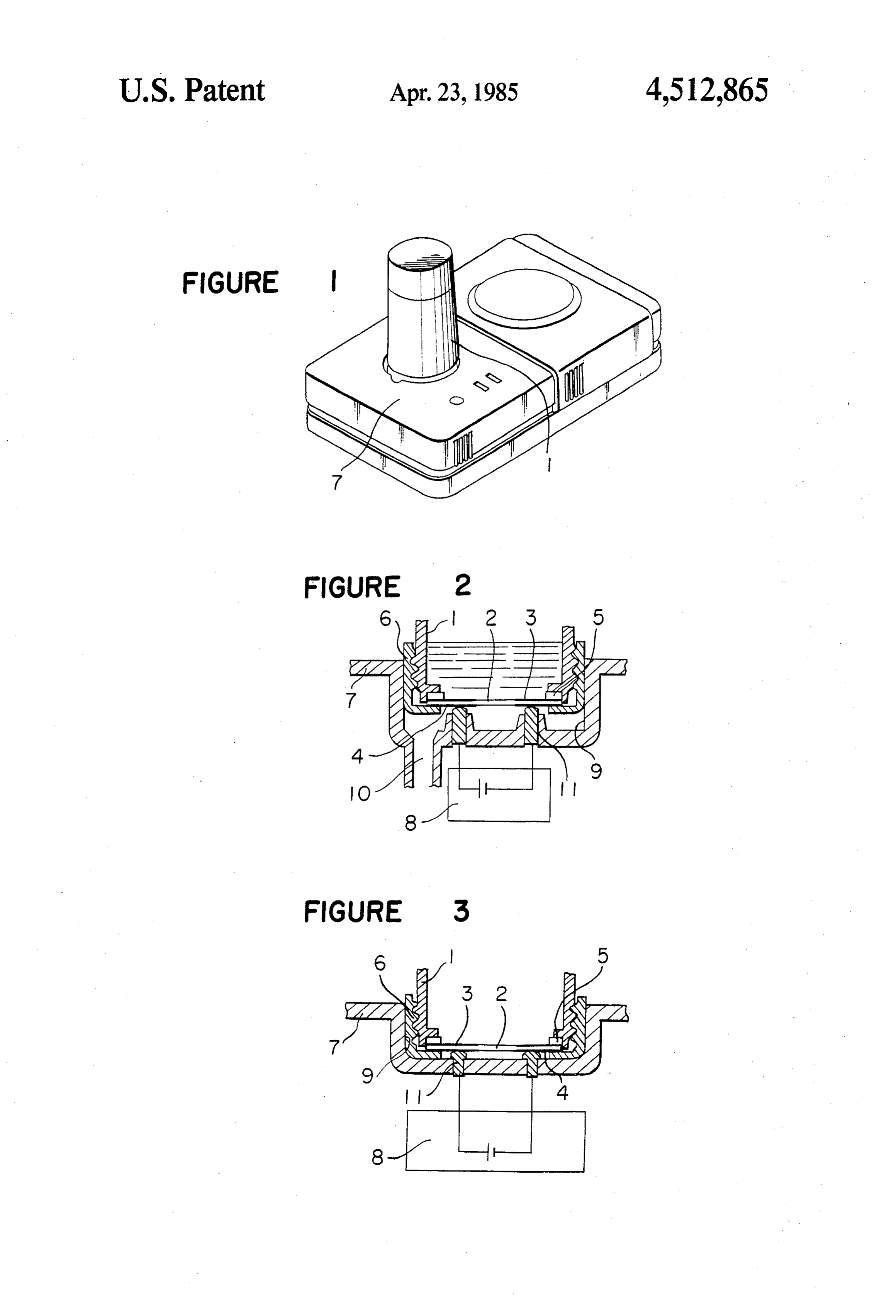
method wherein the contact lenses are sterilized by 50 BRIEF DESCRIPTION OF THE DRAWINGS various disinfectant fluids such as solutions containing, e.g., thinerosal or chlorohexadine. In such a treatment, FIG. 1 is a perspective view of an electrolytic steril the disinfectant component will readily be adsorbed izer according to the present invention, illustrating the into the lens body because of the large structural spaces entire outer appearance thereof.
between molecules constituting the hydrated contact 55 FIG. 2 is a cross sectional view of the essential por lenses. However, the adsorbed disinfectant component tion of the structure for electric connection for the has the potential danger of causing hypersensitive in electrodes in the electrolytic sterilizer of FIG. 1. flammation to the eye tissue. FIG. 3 is a vertical cross sectional view illustrating a There has also been proposed a method wherein the conventional structure for the electric connection for lenses are sterilized with a 3% aqueous solution of hy 60 the electrodes in a prior art sterilizer. drogen peroxide, and then the solution is contacted DETAILED DESCRIPTION OF THE with a catalyst such as platinum to decompose and PREFERRED EMBODIMENTS detoxicate the hydrogen peroxide into water and oxy gen. This method also has disadvantages in that it re Referring to the drawings, reference numeral 1 desig quires a considerably longer time in sterilization and is 65 nates a sterilizing container made of a synthetic resin, impractical because of its complicated operation. and numeral 2 designates an electrode unit for conduct Further, Japanese Unexamined Patent Publication ing an electric current in the sterilizing container 1. The No. 68454/1981 discloses a method wherein contact electrode unit 2 comprises electrolytic electrodes 3 4 formed of a highly ionizable element such as platinum whereby the electrolytic sterilization is conducted by or gold on the upper surface of a ceramic base plate and sodium hypochloride generated in the solution. sterilizing container-side contacts 4 fixed on the lower As is evident from the foregoing description of the surface of the base plate. The respective electrodes 3 construction and the manner of the operation, the pres and contacts 4 are electrically connected along the ent invention has the following advantages. respective sides of the base plate or through through Namely, in the present invention, the main body-side holes provided in the base plate. The electrode unit 2 is contacts are provided outside the waste solution groo fixed on the bottom of the sterilizing container 1 by an ve-i.e., on electrically insulated supports protruded outer cover 6 with a packing 5 interposed in between the from the waste solution groove. Therefore, even if a sterilizing container 1 and the outer cover 6. 10 washing solution or a physiological sodium chloride Reference numeral 7 is a main body accommodating solution is dropped between the contacts, it will be a power source unit 8 which internally contains a bat possible to avoid deposition of such solution between tery. Reference numeral 9 is a groove for waste solution the tops of the main body-side contacts and the contacts provided at the bottom of the recess of the base body 15 of the electrode unit, whereby a stabilized electrolytic designed to receive the sterilizing container 1. The sterilization can be conducted. Further, in the present groove 9 for the waste solution is provided with a dis invention, the washing solution, or a physiological so charge outlet 10. The sterilizing container 1 having the dium chloride solution dropped into the waste solution electrode unit 2 fixed by the outer cover 6, is detachably groove is discharged from the discharge outlet pro fitted in a recess in the main body 7 for each use. vided at the bottom of the groove, whereby the wash Reference numeral 11 designates a pair of contacts on 20 ing the can readily be conducted and it is possible to avoid deposition of foreign matter or stains.
the main body 7. The cores of the contacts 7 are made What is claimed is:
of, e.g., rubber in a conductive cylindrical shape, and 1. An electrolytic sterilizer for contact lenses, said their peripheries are supported by an electrically insula tive support portion protruded from the waste solution 25 sterilizer(a) a comprising:
main body accomodating a power source unit, groove 9 of the main body 7. Thus, the main body-side said main body having a recess in the upper surface contacts 11 are readily electrically connectable with the thereof;
sterilizing container-side contacts 4 whenever the steril (b) a pair of protrusions made of an electrically insu izing container 1 is fitted in the recess of the main body lating material protruding upwardly from the bot 7 for use, but the electrically insulative support portions 30 tom of said recess, said pair of protrusions defining prevent electrolysis from occurring in waste sterilizer a groove in the bottom of said recess which re solution accidentally spilled into the recess in the main ceives wastesterilizer solution accidentally spilled body 7. into said recess in said main body; In a prior art separable type electrolytic sterilizer for (c) a sterilizer container detachably mountable in said contact lenses such as is shown in FIG. 3, it is common 35 recess in said main body; that, as the attaching and detaching of the sterilizing (d) a pair of electrolytic electrodes for conducting an container 1 to and from the main body 7 are repeated electric current in said sterilizer container; every time the sterilizer is used, the disinfectant solution (e) a pair of sterilizing container contacts in electrical leaks from the sterilizing container 1 and deposits on the contact with said pair of electrolytic electrodes; contacts 11 of the main body 7. Moreover, the disinfec 40 and tant solution deposited on the contacts 11 tends to cause (f) a pair of main body contacts in electrical contact undesirable electrolysis outside the sterilizing container with said power source unit, said pair of main body 1. contacts being mounted in and protruding up In contrast, in the separable type electrolytic steril wardly from said pair of protrusions and being izer for contact lenses according to the present inven 45 positioned to make electrical contact with said pair tion, the electrically insulative protrusions are provided of sterilizer container contacts when said sterilizer at the bottom of the recess in the main body 7, and the container is mounted in said recess in said main main body-side contacts 11 are provided on the protru body, whereby:
sion. Moreover, a groove 9 for a waste solution and a (g) the portions of said pair of main body contacts discharge outlet 10 are provided at the bottom of the 50 which come into contact with said pair of sterilizer recess of the main body 7. The contacts 11 are located container contacts are normally above the level of outside the waste solution groove 9, and the above-men waste sterilizer solution accidentally spilled into tioned undesirable electrolysis is unlikely to take place. said recess in said main body and Further, no foreign matter is permitted to interfere with (h) said pair of protrusions made from an electrically the electric connection. Accordingly, no disturbance of 55 insulating material normally prevent electrolysis the electric current is likely to take place. from occurring in wastesterilizer solution acciden Further, it is also possible to sterilize the physiolog tally spilled into said recess in said main body. ical sodium chloride solution for preserving contact 2. An electrolytic sterilizer for contact lenses as re lenses, by filling a bottle capped with the outer cover 6 cited in claim 1 wherein said groove has a discharge having the electrode unit 2, with the sodium chloride 60 outlet.
solution, and fitting the bottle in the main body 7, k ck k
Provenance
- Collection
- Patents citing this work
- Pages
- 4
- Method
- pdftotext (the PDF's own text layer) + pdftoppm 300dpi page scans
- Patent office record
- patents.google.com →
- Source
- Google Patents citing-documents table
- Assignee
- Tanica Electric Co., Ltd.
- Published
- 1985-04-23
- Transcribed from
- patentimages.storage.googleapis.com →