

patent · US4513733A
Oil field steam production and use
30 April 1985
Text
Page 1bibliographic recordscan →
United States Patent (19)
Braun
(54) OIL FIELD STEAM PRODUCTION AND USE
75 Inventor: Minel J. Braun, Akron, Ohio Assignee: The Babcock & Wilcox Company,
New Orleans, La.
(51) Int. Cl.................................................. F24J 3/02 52 U.S. Cl. .................................... 126/435.126/452,
2, 182,545 12/1939 Pace ...................................... 166/57 3,064,418 11/1962 Sanders ...... ... 126/45 X 3,498,381 3/1970 Earlougher ... 166/57 X 3,908,632 9/1975 Poulsen ................ - -- - - - 26/435
4, 174,752 11/1979 Slater et al...................... 126/435 X
4, 195,620 4/1980 Rust .................................... 126/425 4,249,605 2/1981 Slater et al. ..................... 126/435 X 4,296,739 10/1981 Bolding ........................... 126/435 X 4,313,304 2/1982 Hunt ............................... 126/435 X 4,333,445 6/1982 Lee .................................. 126/435 X Primary Examiner-Larry Jones
Attorney,
Edwards Agent, or Firm-James C. Simmons; Robert J.
A method and apparatus for oil field steam production and use. Heated refractory particles are flowed through a steam generator in heat exchange relation with well water to generate steam. In accordance with one aspect of the invention, the steam is flowed into a well to heat oil in the well. In accordance with another aspect of the invention, the refractory particles are heated by flowing through a solar receiver in heat exchange relation with Solar radiation.
14 Claims, 1 Drawing Figure
Drawings
Page 2drawing sheetscan →
Page 3scan →
Oil field steam production and use
The various features of novelty which characterize the invention are pointed out with particularity in the claims annexed to and forming a part of this disclosure.
This invention relates to oil recovery. More particu For a better understanding of the invention, its operat larly, this invention relates to the production of high ing advantages, and specific objects attained by its uses, pressure steam from well water for use in heating the oil reference is made to the accompanying drawings and in a well for recovery thereof. descriptive matter in which a preferred embodiment of As oil becomes more difficult to locate and produce, the invention is illustrated.
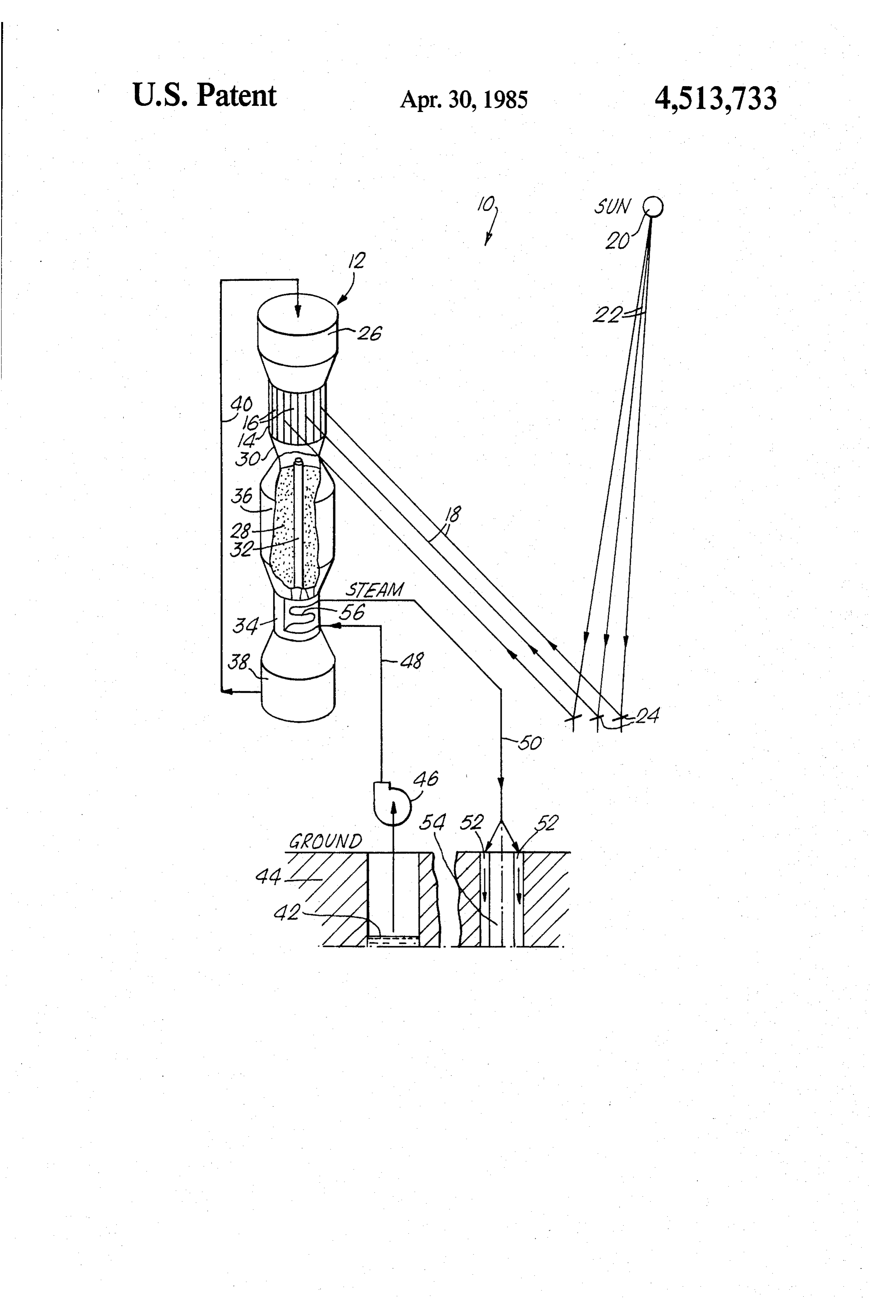
it has become advantageous to drill for oil and recover oil from greater and greater depths and to use second O IN THE DRAWINGS ary oil recovery methods which may require the use of The FIGURE is a view, partly perspective with parts steam for heating the oil so that it may be recovered broken away and partly schematic, of oil heating appa from geological formations and/or so that it may flow ratus embodying the present invention. sufficiently to be recovered. Referring to the drawing, there is shown an apparatus A typical oil field installation is located away from a 15 generally indicated at 10 for generation and delivery of convenient source of steam heat. Since it is not impor steam to an oil well to heat oil and dissolve it out of its tant to minimize the amount of dissolved solids or de geological formation for secondary oil recovery. A gree of contamination of the steam entering the well for solar powered steam generator for generating such use, it is considered advantageous to be able to use steam is indicated at 12. The steam generator 12 is pro untreated well water (that is, brackish water) for such 20 vided with a solar receiver 14 which includes about its steam production. periphery a plurality of panels 16 of tubes or other heat Flowing untreated well water with its large quantity exchange means for flowing a medium therethrough in of dissolved solids such as salt through a steam genera heat exchange relation with solar radiation energy di tor in heat exchange relation with flue gases of a typical rected onto the panels 16 as schematically shown by fossil fuel-fired steam generator or with solar radiation 25 arrows 18. The solar radiation energy 18 is directed energy of a solar receiver is not considered economi onto the panels 16 from the sun schematically illustrated cally feasible since the temperatures of flue gases and at 20 by redirection of the suns rays 22 onto the panels solar radiation directed onto a receiver are typically in 16 by means of a field of heliostat mirrors schematically the range of 2000 to 3000 degrees Fahrenheit at which illustrated at 24.
temperatures there is a likelihood of severe corrosion 30 An heat exchange medium is introduced into the solar and tube failures if untreated well water is flowed in receiver from hopper 26 under gravitational force to heat exchange therewith. flow vertically downwardly through the solar receiver The use of a reboiler system wherein sufficiently pure 14 in heat exchange relation with the solar radiation water is flowed in heat exchange relation with flue energy 18 to receive heat therefrom.
gases or solar radiation energy and the steam produced 35 If molten salts or liquid metals are used as an heat therefrom is flowed in heat exchange relation with well exchange medium, functional containment and environ water is limited to producing steam from well water at mental problems result. Among these is the continual pressures not over about 600 to 800 psi due to inherent requirement of keeping the molten salt or liquid metal in heat exchange limitations (that is, those limitations re a fluid state in all tube passages and storage areas. A sulting from the properties of steam as shown on a Mol 40 breakdown in the plant, forcing even a temporary shut lier diagram). However, the depths of penetration of down, may cause the solidification of the molten salt or many typical oil wells is such as to require higher steam liquid metal resulting in extremely difficult problems for pressures in the range of 2200 to 3000 psi for secondary restarting the plant. In addition, molten salt is corrosive oil recovery. to the usual metal surfaces with which it comes in It is therefore an object of the present invention to 45 contact. Molten metal such as liquid sodium can also be generate steam at pressures in the range of 2200 to 3000 dangerous when brought in contact with air or water. psi from untreated well water without the disadvan In order to provide a medium for flowing through the tages described above. solar receiver in heat exchange relation with the solar It is another object of the present invention to use an radiation energy that is inexpensive, environmentally inexpensive and readily accessible heat source to gener 50 safe, non-corrosive, and does not present operating ate such steam. difficulties if its temperature drops below or rises above It is still another object of the present invention to normal operating temperatures, in accordance with the generate such steam for secondary oil recovery on a present invention the medium which is provided is a continual basis; that is, 24 hours a day. moving bed of sand or other refractory particles illus It is yet another object of the present invention to 55 trated at 28 which remain in the form of granulated generate such steam by utilizing solar radiation energy solids throughout the normal operating and shut-down with low cost and maintenance. temperatures of the steam generator 12. By "moving It is another object of the present invention to elimi bed' is meant granulated solids in a process vessel that nate the economical unattractive alternatives of the are circulated (moved) either mechanically or by grav prior art in order to provide a significant advantage for 60 ity flow. This is in contrast to a "fluidized bed” which generation of high pressure steam from untreated well is defined herein as a cushion of air or hot gas or liquid water for secondary oil recovery at the typical depths floating or otherwise conveying a powdered material of oil well penetration. through a process vessel. The free flowing refractory It is another object of the present invention to pro particles 28 are preferably spherical in shape, have a vide an apparatus and method for high pressure steam 65 uniform size of preferably about 100 microns, and are of generation from untreated well water which is simple in course preferably inexpensive. Acceptable materials design, rugged in construction, economical to manufac include but are not limited to silica sand, barytes sand ture, and economical to operate and maintain. (barium sulfate), partially calcined clay, glass beads, and 4 reclaimed petroleum catalysts. In the embodiment of water 42 which is flowed through the steam generator the invention described herein, silica sand is used as the through tubes 56 to heat the well water to generate heat exchange medium. steam. The remaining refractory particles 28 may be After flowing through tubes or other heat exchange stored in reservoir 36 for use at a later time. The gener means in the solar receiver, the hot refractory particles ated steam is then flowed through line 50 into the spaces 28 flow by gravity to a mixing chamber 30 from which 52 to heat oil in the well 54 for secondary oil recovery. some of the particles may be directed through a thru In a typical secondary oil recovery installation, feeding duct 32 for immediate feeding under gravita 16,300 lbs per hour of sand may be flowed through the tional force to heat exchanger 34. In order for the steam solar receiver 14 and heat exchanger 34. In contrast to generator 12 to have the capacity to generate steam O the unacceptable corrosion levels which would result if continually, one or more hot refractory particle reser flue gas or solar radiation in the higher temperature voir means 36 is provided to store the hot refractory range of 2000 to 3000 degrees Fahrenheit were used for particles for use during periods of low solar insolation directly heating untreated well water, sand or other such as at night. refractory particles is used as the heat exchange me The hot refractory particles 28 are delivered from the 15 dium to reduce to very low levels the degree of corro bottom of the thru-feeding duct 32 and/or reservoirs 36 sion and wear of solar panel tubes to thereby reduce the as the solar insolation conditions and steam use require tube failure rate and solar receiver maintenance costs. to the heat exchanger 34 preferably undergravitational The sand enters the solar receiver 14 at about 225 de force to flow downwardly in heat exchange relation grees Fahrenheit and is heated to about 1200 to 1300 with water flowing through tubes illustrated at 56 20 degrees Fahrenheit in the solar receiver. In its passage thereof. After yielding its thermal energy to the water, through the heat exchanger 34 the temperature of the the cool energy wasted sand or refractory particles is sand is reduced back to 225 degrees Fahrenheit in heat collected in storage bin 38. It is preferable that the heat ing well water flowing in counterflow relation to the exchanger 34 be located below the thru-feeding duct 32 sand at an inlet temperature of 150 degrees Fahrenheit and reservoirs 36 which are in turn preferably located 25 and at a rate of 3455 lbs per hour. Steam of a quality of below the receiver 14 to advantageously allow the flow 0.8 is generated at a pressure of 1000 psi. of refractory particles from the hopper 26 through the By varying the flow rate of sand through the solar heat exchange cycle to the storage bin 38 under the receiver and the solar receiver panel sizes in accordance force of gravity so as to eliminate any requirements for with engineering principles of common knowledge to complicated mechanical handling of the hot refractory 30 those of ordinary skill in the art to which this invention particles. pertains, a sand temperature at the outlet of the solar As needed, the cooled refractory paticles 28 are receiver 14 in the range of 1500 to 1800 degrees Fahren transported to the hopper 26 by suitable means schemat heit can be provided. Such a sand temperature is capa ically illustrated at 40 such as, for example, a belt, ble of heating water in the heat exchanger 34 to provide bucket conveyors, or an Archimedes screw conveyor, 35 saturated steam in the temperature range of 650 to 695 and the cycle is repeated. degrees Fahrenheit which corresponds to pressures in In accordance with the present invention, untreated the range of 2200 to 3000 psi suitable for deep penetra brackish well water illustrated at 42 is pumped out of tion in oil wells.
the ground illustrated at 44 by suitable means such as It is believed that significant erosion of heat ex immersion pump 46 through line 48 to the heat ex 40 changer tubes by flowing sand will not occur as long as changer 34 wherein the water 42 is flowed preferably in the velocity of sand through the heat exchanger tubes is counter-flow or cross-flow heat exchange relation with less than 5 feet per second.
the hot refractory particles 28 in a once-through ar A particular construction of an apparatus for heating rangement to receive heat from the hot refractory parti oil for secondary oil recovery in accordance with this cles 28 to generate saturated quality steam. The result- 45 invention can be designed using engineering principles ing steam is then delivered by suitable means such as of common knowledge to those of ordinary skill in the line 50 and spaces 52 to the location of oil in well illus art to which this invention pertains. Certain features of trated at 54 for heating the oil for secondary oil recov this invention may sometimes be used to advantage ery. without a corresponding use of the other features. It is In accordance with a preferred embodiment of the 50 also to be understood that the invention is by no means present invention, refractory particles 28 are flowed limited to the specific embodiments which have been downwardly through the solar receiver 14 in heat ex illustrated and described herein, and that various modi change relation with solar radiation 18 to heat the re fications thereof may indeed be made which come fractory particles 28 to thereby result in reduced cost within the scope of the present invention as defined by and maintenance of solar panels since they are not sub- 55 the appended claims.
ject to high mineral content water; ie, well water. Al I claim:
though solar energy for generating steam is a free and 1. A method of heating oil in a well comprising: renewable source of energy, and although the use of a a. flowing heated refractory particles through a steam Solar receiver in the steam generator 12 takes advantage generator;
of many oil fields being situated in warm climates com 60 b. pumping untreated well water the source of which patible with the use of solar energy, other suitable is the ground from out of the well through a first means such as the burning of fossil fuel in fossil fuel cavity in the ground and through tube means in the fired boilers may be used to provide heated refractory steam generator in heat exchange relation with the particles for flowing through the steam generator 34. heated refractory particles to heat the untreated Some of the refractory particles may then be flowed 65 well water to generate steam; and downwardly through thru-feeding duct 32 afterwhich c. flowing the steam into the well through a second they are immediately flowed downwardly through cavity in the ground to heat oil in the well. steam generator 34 in heat exchange relation with well 2. A method of heating oil in a well comprising:
Page 5scan →
a. flowing refractory particles through a solar re exchange relation with solar radiation energy to heat ceiver in heat exchange relation with solar radia the refractory particles, means for pumping untreated tion to heat the refractory particles; well water the source of which is the ground from out b. flowing the heated refractory particles through a of a well through a first cavity in the ground, steam steam generator; generating means for flowing untreated well water c. pumping untreated well water the source of which pumped from the well through tube means in heat ex is the ground from out of the well through a first change relation with the heated refractory particles to cavity in the ground and through tube means in the steam generator in heat exchange relation with the generate steam, and means for routing the steam into the heated refractory particles to heat the untreated O the well. a second cavity in the ground to heat oil in well through well water to generate steam; and d. flowing the steam into the well through a second a 9.moving Apparatus according to claim 8 further comprising bed of refractory particles for flowing cavity in the ground to heat oil in the well. through said solar receiver and said steam generator. 3. A method according to claim 2 further comprising disposing the steam generator below the solar receiver 15 10. Apparatus according to claim 8 wherein said and gravity flowing the refractory particles through the steam generator is disposed below said solar receiver steam generator and solar receiver. for gravity flowing of the refractory particles through 4. A method according to claim 2 further comprising the solar receiver and steam generator. storing at least a portion of the heated refractory parti 11. Apparatus according to claim 8 further compris cles for use in generating steam during periods of low 20 ing means for storing at least a portion of the heated . solar insolation. refractory particles for use in generating steam during 5. A method according to claim 4 further comprising periods of low solar insolation.
disposing the steam generator below the solar receiver 12. Apparatus according to claim 11 wherein said and gravity flowing the refractory particles through the steam generator is disposed below said solar receiver steam generator and solar receiver. 25 for gravity flowing of the refractory particles through 6. A method according to claim 5 further comprising the solar receiver and steam generator. transporting the cooled refractory particles to the solar 13. Apparatus according to claim 12 further compris receiver for again flowing through the solar receiver. ing means for transporting the cooled refractory parti 7. A method according to claim 5 further comprising cles to the solar receiver for flowing through the solar storing the heated refractory particles at a location 30 receiver.
which is intermediate the solar receiver and the steam 14. Apparatus according to claim 12 wherein said generator. storage means is disposed intermediate said solar re 8. Apparatus for heating oil in a well comprising solar ceiver and said steam generator.
receiver means for flowing refractory particles in heat k ck sk ck ck
Provenance
- Collection
- Patents citing this work
- Pages
- 5
- Method
- pdftotext (the PDF's own text layer) + pdftoppm 300dpi page scans
- Patent office record
- patents.google.com →
- Source
- Google Patents citing-documents table
- Assignee
- The Babcock & Wilcox Company
- Published
- 1985-04-30
- Transcribed from
- patentimages.storage.googleapis.com →