

patent · US4515093A
Method and apparatus for the recovery of hydrocarbons
7 May 1985
Text
Page 1bibliographic recordscan →
United States Patent (19)
Beardmore et al.
(54) METHOD AND APPARATUS FOR THE
RECOVERY OF HYDROCARBONS
76 Inventors: David H. Beardmore; Riley B.
Needham, both c/o Phillips
Petroleum Company, Bartlesville,
51 Int. Cl. ................................................ F23D 1/OO 52 U.S. Cl. ...................................... 110/347; 48/203;
3,124,086 3/1964 Sage et al....... m ... 110/347 3,856,455 12/1974. Otway et al. 431/173 3,971,847 7/1976 Houseman ... 431/163 4,030,889 6/1977 Gunnell ....... ... 43/173 4,147,116 4/1979 Graybill .. ... 10/263 4,245,569 1/1981 Fallon ..... 110/215 4,374,650 2/1983 Garside ....... ... 48/203 4,378,974 4/1983 Petit et al. ............................. 48A210
4,387,654 6/1983 Binasik et al. ....................... 10/261 4,397,295 8/1983 Bakker ................................ 110/261 4,407,205 10/1983 Beaufrere ............................ 10/347
FOREIGN PATENT DOCUMENTS
74930 6/1977 Japan ................................... 431/173 162524 12/1980 Japan ................................... 431/163 Primary Examiner-Edward G. Favors
Assistant Examiner-Steven E. Warner
A method for generating steam by a high pressure, high intensity, or high heat release method of combustion in an elongated combustion zone having upstream and downstream ends and an intermediate location and uti lizing a normally-solid fuel which produces non-com bustible solid residues in which the fuel is introduced axially and a volume of air, at least equal to the stoichio metric amount, is introduced as an annular, rotating stream to produce a rotating vortex of fuel and air, such introduction and flow through the combustion zone being carried out in a manner to collapse the vortex and create plug flow at the intermediate location, burning the fuel and air to produce flue gas at a heat release rate of at least 7 MM Btu/hr, abruptly terminating combus tion by the introduction of water, vaporizing the water to produce a mixture of flue gas and steam, and separat ing solid residues therefrom.
18 Claims, 1 Drawing Figure
SEEAM 8.
FLUE CAS
Drawings
Page 2drawing sheetscan →
Page 3scan →
nation of well bore losses by the use of insulated tubing
METHOD AND APPARATUS FOR THE for the injection of steam.
RECOVERY OF HYDROCARBONS In addition, numerous heavy oil reservoirs will not respond to conventional steam injection since many
The present invention relates to the method and appa have little or no natural drive pressure of their own and ratus for the recovery of hydrocarbons. More specifi even when reservoir pressure is initially sufficient for cally, the present invention relates to a method and production, the pressure obviously declines as produc apparatus for the recovery of hydrocarbons by the use tion progresses. Consequently, conventional steaming of steam. techniques are of little value in these cases, since the 10 steam produced is at a low pressure, for example, sev
Background of the invention
eral atmospheres. Consequently, continuous injection of
With the rapidly declining availability of hydrocar steam, or a 'steam drive' is generally out of the ques bon fuels, particularly from petroleum sources, there is tion. As a result, a cyclic technique, commonly known a great need to extend efforts for the recovery of the as "huff and puff" has been adopted in many steam petroleum to sources heretofore practically or economi 15 injection operations. In this technique, steam is injected cally unattractive and to the recovery of hydrocarbon for a predetermined period of time, steam injection is fuels from alternate sources. A major potential source discontinued and the well shut in for a predetermined of petroleum, which has heretofore been virtually un period of time, referred to as a “soak”. Thereafter, the tapped because of the inability of most refineries to well is pumped to a predetermined depletion point and handle such crudes and the inability and expense of 20 the cycle repeated. This technique has the disadvan recovering them, are heavy oil deposits. Two basic tages that it depends for the recovery of oil, solely on a methods have heretofore been applied in the recovery decrease in viscosity of the oil and the steam penetrates of such heavy oil deposits, namely; in situ combustion only a very small portion of the formation surrounding and steam injection methods. Both of these techniques the well bore, particularly since the steam is at a rela have been limited by the fact that both require the burn 25 tively low pressure.
ing of substantial amounts of the oil itself, or equivalent However, the most formidable problem with conven fuels, in order to reduce their viscosity and permit pro tional steam generation techniques is the production of duction thereof. This is true even with increased prices air pollutants, namely, SO2, NOx and particulate emis of oil. For example, to evaluate the economics of steam sions. By way of example, it has been estimated that injection, the oil/steam ratio (OSR) is utilized. The 30 when burning crude oil having a sulfur content of about OSR is the ratio of additional oil recovered for each ton 2%, without flue gas desulfurization and utilizing 0.3 of steam injected. Since it is necssary to burn about barrels of oil as fuel per barrel of oil produced, air emis eight tons of fuel to get one hundred tons of steam, an sions in a San Joaquin Valley, Calif. operation would OSR of 0.08 has a thermal balance of 0; i.e., you burn as amount to about 40 pounds of hydrocarbons, 4,000 much oil to generate the steam as you produce. Gener 35 pounds of SO2, 800 pounds of NOx and 180 pounds of ally, wells in the Kern River Field of California operate particulates per 1,000 barrels of oil produced. When with an OSR of 0.24, and are abandoned when they get these figures are multiplied in a large operation and a below 0.15. number of such operations exist in a single field, the However, with the decontrol of heavy oil prices problems can readily be appreciated. Consequently, several years ago, substantial work has been done and 40 under the Clean Air Act, the Environmental Protection commercial operations are presently under way utiliz Agency has set maximum emissions for such steaming ing steam recovery techniques for the recovery of operations, which are generally applied area wide, and heavy oil. In addition, the technology has progressed to states, such as California where large heavy oil fields the point where application of steam technology to exist and steaming operations are conducted on a con other resource areas such as tar sands, diatomaceous 45 mercial scale, have even more stringent limitations. earth, oil shale, and even residual light oil are techni Consequently, the number of steaming operations in a cally feasible. However, until fairly recently, the state given field have been severely limited and in some cases of the art techniques for heavy oil production by steam it has been necessary to completely shut down an opera injection have produced only about 40% to 55% of the tion. The alternative is to equip the generators with oil in place. This of course, is close to the ragged edge 50 expensive stack gas scrubbers for the removal of SO2 of being economic and leaves substantial volumes of oil and particulates and to adopt sophisticated NOx control unrecovered. techniques. This, of course, is a sufficiently large cost to Most commercial operations, at the present time, are make many operations uneconomic. Further, such confined to the use of conventional steam boilers for the scrubbers also result in the production of toxic chemi generation of steam. Usually, the lease crude is used as 55 cals which must be disposed of in toxic chemical dumps a fuel. However, when one considers that 80% to 85% or in disposal wells where there is no chance that they of the cost of a steam injection operation is cost of the will pollute ground waters.
fuel, this obviously is a major factor. As a result, a num It has also been proposed to utilize high pressure ber of alternate energy sources, some rather exotic, combustion systems at the surface of the earth. Such a have been suggested, including petroleum coke, low 60 system differs from the low pressure technique to the BTU lignite coal, natural gas, almond hulls and tree extent that the water is vaporized by the flue gases from prunings, solar energy, etc. However, except for solar the combustor and both the flue gas and the steam are energy, all suggested and used sources of energy for injected down the well bore. This has been found to steam generation have the same problems and disadvan essentially eliminate, or at least reduce or delay, the tages. 65 necessity of stack gas clean up and use of NOx reduction First of all, conventional steam boilers waste about techniques. The mixture conventionally has a composi 19% of the fuel value in stack losses. Considerable work tion of about 60% to 70% steam, 25% to 35% nitrogen, has been done and progress has been made in the elimi about 4% to 5% carbon dioxide, about 1% to 3% oxy 4 gen, depending upon the excess of oxygen employed for techniques of steam generation, where steam is pro complete combustion, and traces of SO2 and NOx. The duced in a conventional boiler and the flue gas is not SO2 and NO, of course, create acidic materials. How used.
ever, potential corrosion effects of these materials can It is therefore and object of the present invention, to be substantially reduced or even eliminated by proper overcome the above-metnioned and other disadvan treatment of the water used to produce the steam. There tages of the prior art. Another object of the present is a recognized bonus to such an operation, where a invention is to provide an improved method and appa combination of steam, nitrogen and carbon dioxide are ratus for the generation of steam for hydrocarbon re utilized, as opposed to steam alone. In addition to heat covery which reduces heat losses. Another and further ing the reservoir and oil in place by condensation of the O object of the present invention is to provide an im steam, the carbon dioxide dissolves in the oil, particu proved method and apparatus for generating steam for larly in areas of the reservoir ahead of the steam where hydrocarbon recovery capable of pressurizing and/or the oil is cold and the nitrogen pressurizes or repressur repressurizing petroleum reservoirs. A still further ob izes the reservoir. In fact, in certain types of reservoirs ject of the present invention is to provide an improved it is believed that the nitrogen creates artifical gas caps 15 method and apparatus for generating steam for hydro which aid in production. As a result of field tests, it has carbon recovery which greatly reduces or delays envi been shown that the high pressure technique results in ronmental pollution. Yet another object of the present at least a 100% increase in oil production over the use of invention is to provide an approved method and appara steam alone and shortening the time of recovery to tus for generating steam for hydrocarbon recovery about two-thirds of that for steam injection alone. Such 20 which is safe to use at the surface of the earth. Another tests have generally been confined to injection of steam object of the present invention is to provide an im utilizing the “huff and puff" techinque, primarily be proved method and apparatus for generating steam for cause results are forthcoming in a shorter period of time hydrocarbon recovery including a combustor having a and comparisons can be readily made. However, utiliza high power output. A further object of the present tion of the high pressure technique insteam drive opera 25 invention is to provide an improved method and appa tions should result in even further improvements. A ratus for the production of steam for hydrocarbon re very serious problem, however, with the currently pro covery capable of operating at a high pressure. Another posed above ground high pressure system is that it in and further object of the present invention is to provide volves a large hot gas generator operating at high pres an improved method and apparatus for the production sures and high temperatures. This creates serious safety 30 of steam for hydrocarbon recovery, including a com hazards and, when operated by unskilled oil field per bustor having a high combustion stability and combus sonnel, can have the potential of a bomb. In order to be tion efficiency. A still further object of the present in effective, for steam injection, the power output of the vention is to provide an improved method and appara combustor should be at least about 7 MM Btu/hr. In tus for the generation of steam which utilizes fuels order to be useful in a sufficiently large number of reser 35 which produce solid residues. Another and further ob voirs, the output pressure must be above about 300 psi. ject of the present invention is to provide an improved The combustor must also be precisely controlled so as method and apparatus for generating steam, utilizing a to maintain flame stability and prevent flame out, turbu fuel which produces solid residues, in which the solid lent flow, etc. Such control must also be exercised in residues are effectively removed and clean flue gas is feeding and maintaining proper flow of fuel and com 40 advantageously mixed with the steam. Another and bustion supporting gas and combustion stoichiometry further object of the present invention is to provide an for efficient and complete combustion, thereby elimi improved method and apparatus for the generation of nating incomplete combustion with the attendant pro steam for hydrocarbon recovery capable of producing duction of soot and other particulate materials, since clean, dry steam. A further object of the present inven excessive amounts of combustion supporting gas for 45 tion is to provide an improved method and apparatus stoichiometric combustion could contribute to corro for the generation of steam for hydrocarbon recovery sion and excessive amounts of fuel result in incomplete capable of efficient and complete production of steam. combustion and the production of soot and other partic Yet another object of the present invention is to provide ulates. A further problem is the construction of the an improved method and apparatus for the generation combustor and its operation to prevent rapid deteriora 50 of steam for hydrocarbon recovery wherein water for tion of the combustion chamber and the deposition of the production of steam is introduced in a manner carbonaceous materials in the walls of the combustion which prevents the interference of the water with com chamber. Thus, proper cooling of the combustion bustion and effectively mixes the water with combus chamber is necessary, as well as protection of the walls tion products. These and other objects of the present of the combustion chamber. Efficient evaporation and 55 invention will be apparent from the following descrip control of the water are also necessary to produce dry, tion.
clean steam. Unless the combustor is properly con SUMMARY OF THE INVENTION trolled, in addition to introducing the water into the flue gas properly, the water will prematurely dilute the The present invention relates to a method of generat combustion mixture, resulting in incomplete combus 60 ing steam, particularly for the recovery of hydrocar tion and creation of the water-gas reaction, as opposed bons, utilizing fuels which produce solid residues, such to combustion, and prematurely cool the combustion as ash producing coals, lignites, etc., in which the fuel is mixture, again producing excessive soot and particu burned in an elongated combustion chamber and in the lates. The production of solids is particularly serious presence of a combustion supporting gas in an amount when utilizing fuels which produce solid residues, such 65 at least equal to the stoichiometric amount necessary for as ash producing coal, lignite, etc. Consequently, to combustion of essentially all of the combustible portion prevent pluggin of the formation, the use of fuels which of the fuel to produce a flue gas containing solid resi produce solid residues has been confined to indirect dues of the fuel, introducing water into the flue gas 5 adjacent the outlet end of the combustion chamber, tion chamber in a manner such that the water will pene maintaining the resultant mixture of flue gas and water trate to essentially the central axis, thus rapidly quench in a vaporization chamber having its inlet end directly ing the hot flue gases and mixing them with the water. coupled to the outlet end of the combustion chamber Preferably, the water is supplied to the combustion for a time sufficient to vaporize a major portion of the chamber from the annular plenum 44 through a plural water and produce a mixture of flue gas and steam, and ity of apertures 46, which thus introduce the water as a separating the solid residues from the mixture offlue gas plurality of radial jets spaced about the periphery of the and steam to produce a mixture of flue gas and steam combustion chamber. Mixing of the flue gas and water essentially free of solid residues. can be greatly enhanced by reducing the diameter of the 10 exiting flue gases by an orifice or nozzle 48 and intro
Brief description of the drawing
ducing the water immediately before, within, or imme
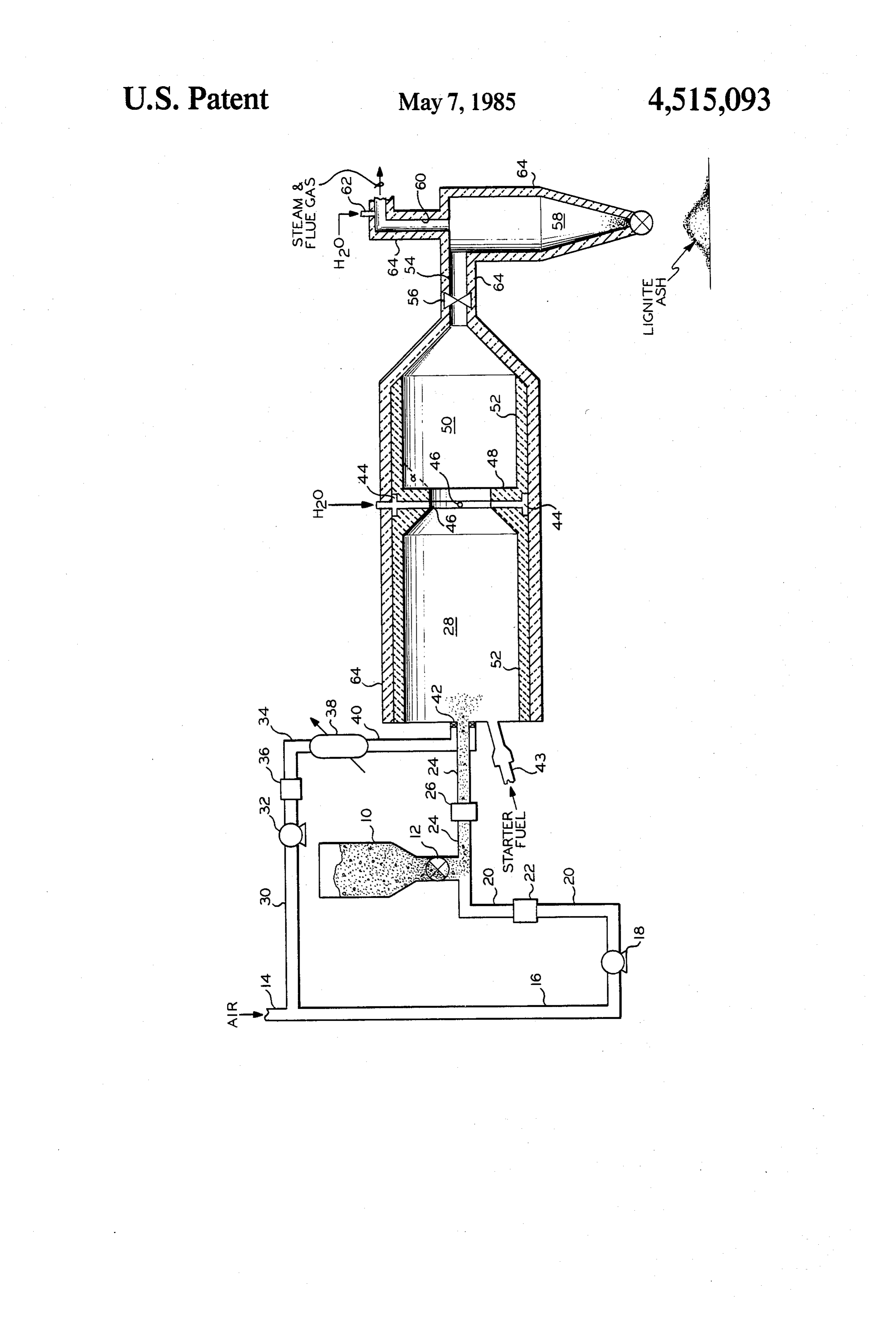
The single FIGURE of the drawings is a simplified diately after the reduced portion of the flue gas. In the flow-type diagram of a system for producing steam in preferred arrangement, the water is introduced into the accordance with the present invention. reduced diameter portion of the flue gas. After passing 5 through the orifice or nozzle 48, the flue gas or the
Description of the preferred
EMBODIMENTS mixture of flue gas and water is abruptly expanded into vaporization chamber 50. This abrupt expansion also
The nature of the features and the operation of the aids in mixing the water and flue gas by reverse circula method and apparatus of the present invention will be tion. A similar effect can be obtained by simply elimi better understood by the following description when 20 nating the orifice or nozzle 48 and abruptly expanding read in conjunction with the drawing. the flue gas or flue gas-water mixture into a vaporiza In accordance with the drawing, pulverized coal is tion chamber which is larger than the combustion supplied by means of a pressurized bin 10, having chamber. In either case, the abrupt expansion should be mounted in its bottom an appropriate feeder means, such that the angle alpha with respect to the wall of the such as a rotary air lock feeder 12. Transport air for the 25 combustion chamber is greater than about 15, in the coal feed is supplied from an appropriate air source, (not present case, 90, in order to prevent streamline flow shown) through line 14, thence through line 16 to a first along the walls of the combustion chamber. This ar air compressor 18. The compressed air then passes rangement of reduction and expansion or expansion, through line 20, having mounted therein flow meter 22. together with the introduction of the water immediately The air is then combined with the coal and passed 30 adjacent such reduction and expansion or expansion has through line 24, having mounted therein pulse elimina the further advantage that is prevents back flow of tor 26. The pressurized mixture of air and coal is then water into the combustion chamber 28 and thus prema fed into the upstream or inlet erid of an elongated com ture quenching or cooling of the flue gases. The previ bustion chamber 28 of the steam generator. Additional ously mentioned torroidal vortex of fuel and air in com air from line 14 is fed to the combustor through line 30 35 bustion chamber 28 is necessary to the operation of the to compressor 32. The compressed air then passes from system of the present application to the extent that compressor 32 through line 34, which has mounted flame speed is to be maintained substantially above therein flow meter 36. The compressed air from line 34 laminar flame speed. If the velocity substantially lami passes to an air heater 38, where the air is heated to an nar flame speed is employed without creation of a tor appropriate temperature and then is passed through line 40 roidal vortex or the like, the flame will have a tendency 40 to combustion chamber 28. Preferably, the com to go out and will be unstable. The subject torroidal pressed and heated air is introduced into the inlet end of vortex collapses toward the downstream end of com combustion chamber 28 through appropriate swirling bustion chamber 28 and flow changes to a uniform flow or rotating mechanism 42, thus forming a swirling or across the cross section of the combustion chamber or rotating annular stream of air about the fuel. A torroidal 45 plug type flow. The interior of combustion chamber 28 vortex of fuel and air is formed in combustion chamber and vaporization chamber 50 are lined with a ceramic 28, which not only produces intimate mixing of the fuel or refractory lining 52 in order to prevent deposits from and air but also stabilizes the flame in combustion cham forming on the walls and destruction of the walls by the ber 28 due to the fact that fuel, partially combusted fuel hot gases, particularly in the combustion chamber. Ac and air feedback into the central vacuum of the vortex. 50 cordingly, since combustion has been essentially com The total air supplied to combustion chamber 28 is plete and the temperature has been substantially re supplied in an amount sufficient to provide stoichiomet duced by the time the mixture enters the vaporization ric combustion of the fuel in an amount at least equal to chamber 50, it may not be necessary to provide a refrac the stoichiometric amount necessary for combustion of tory lining in combustion chamber 28 in some cases. essentially all of the combustible portion of the fuel, for 55 The direct coupling of the inlet end or upstream end of example, anywhere from 3 to 15 percent excess over the vaporization chamber 50 to the outlet end or the down stoichiometric amount. The mixture of fuel and air is stream end of combustion chamber 28, has a number of ignited or heated to the ignition temperature by a pro very distinct advantages in accordance with the present pane torch lighter 43. The fuel and air are maintained in invention. If the two units were separate and the solid combustion chamber 28 for a residence time sufficient 60 residues or ash in the flue gas were spearated between, to essentially complete combustion and produce an separation equipment would be subject to and require effluent comprising flue gas containing solid residues provision for the handling of flue gases that are high from the fuel, in the case of coal, ash. In order to gener pressure and a high temperature, for example, in the ate steam, water is supplied to a plenum chamber 44, range of about 1300 to 1500 F. This, of course, is a which then feeds the water into the flue gas adjacent to 65 severe limitation. In addition, if the coal or fuel is fed to the downstream end of the combustion chamber. Pref the combustion chamber 28 as a slurry of coal and wa erably, the water is introduced into the flue gas in a ter, for example, the separation equipment would also radial direction toward the center axis of the combus be subjected to severe corrosion problems since most 6 fuels which produce solid residues or ash also contain means causing eventual plugging. Therefore, it is desir significant amounts of sulfur, which results in the pro able to cool this portion of the introduction means to duction of sulfur oxides and the burning of the fuel with prevent the build up of deposits on the inner surface of air results in the production of significant amounts of the introduction means. Such cooling is conveniently nitrogen oxides, both of which produce strong acids in 5 carried out by passing a stream of cooling fluid, for the presence of water. example, water, through an annular space formed about The mixture of flue gas and water is maintained in this portion of the fuel introduction means. vaporization chamber 50 for a residence time sufficient As previously indicated, combustion supporting gas, to vaporize a major portion of the water, depending particularly air, or additional air, if air is used as a trans upon the quality of steam desired. The mixture of steam 10 port medium, is introduced into the combustion cham and flue gas is discharged from the outlet or down ber as a swirling or rotating annular stream about the stream end of vaporization chamber 50 through line 54. stream of fuel to thereby form a torroidal vortex rotat Line 54 is also provided with an appropriate pressure ing in a clockwise or counterclockwise direction and control valve 56 adapted to maintain the pressure moving from the upstream end toward the downstream within the combustor at design operating pressure and 15 end of the combustion chamber. This torroidal vortex is thus control the outlet pressure of the mixture of steam necessary to maintain flame stability and prevent flame and flue gas. Such a valve can be automatic and can also out, etc. in a high pressure combustor, which is the be mounted in the downstream or outlet end of vapori preferred embodiment in the present case. This torroi zation chamber 50. The mixture of steam and flue gas dal vortex eventually collapses before reaching the passing through line 54 and containing solid residue or 20 downstream end of the combustion chamber and ash from the fuel is then passed to an appropriate sepa changes to a uniform flow across the combustor or a rator means 58, such as one or my cyclonetype separa "plug-type' flow. In the case illustrated in the draw tors. In separator 58, the solid residues or ash, which ings, the diameter of the combustor is generally greater would tend to plug the producing formation into which than about 6 inches. However, the diameter should be the stimulating fluid is to be injected, is separated and 25 maintained small, for example, about 13 inches in diame discarded while the clean mixture of steam and flue gas ter in order to increase the safety of the device. By is discharged through line 60. The steam and flue gas maintaining the diameter small, the generator can be mixture for hydrocarbon recovery is preferably passed operated at high pressure and be as safe as conventional to the well head through line 60, for injection into a process heaters and the like as opposed to potentially subsurface formation. If desired, additional water may 30 dangerous, the extremely large high pressure combus be supplied to the mixture of steam and flue gas through tor suggested and tested by the prior art workers. In the line 62 in order to adjust the steam quality to the desired particular instance shown, the interior of the combustor level. In most instances, however, the steam should be is lined with a refractory material to prevent build up of superheated steam, since a certain amount of heat loss deposits on walls of the combustor and damage to the will occur in injecting the recovery fluid down the well 35 walls of the combustor, as would be the case if the bore. The combustion chamber, the vaporization cham combustor were a steel pipe or the like. In addition, a ber, the flow lines to the separator, the separator and the conventional insulation may be wrapped about the flow lines to the point of utilization and, if utilized in a outer surface of the combustor. However, it is also subsurface formation, the flow line in the well should be within the scope of the present invention to cool the provided with an appropriate insulation 64. 40 walls of the combustor by indirect heat exchange, for In the operation of the system of the present inven example, with a portion of the water later introduced tion, the pulverized fuel, such as coal, lignite, etc., is into the flue gas being passed through an annular space generally ground to a size such that about 70 to 80 about the outer surface of a steel pipe or the like. In this percent thereof will pass through a 200 mesh screen case, it is also desirable to utilize a portion of the com (U.S. Standard Sieve) thus having a maximum size of 45 bustion supporting gas to prevent the formation of de about 74 microns. As shown in the drawing, the solid posits and damage to the interior of a steel combustion fuel may be introduced into the combustor suspended in chamber. This can be accomplished by introducing a a pressurized transport gas, such as air. However, it is second portion of air as a swirling or annular stream also contemplated that the solid fuels may be intro between the first torroidal vortex and the wall of the duced in admixture with water, for example, as a water 50 combustion chamber and rotating in the opposite direc fuel solution for "disruptive vaporization' of fuel drop tion of the torroidal vortex. The total volume of air lets, as a water-fuel emulsion, for "explosive atomiza introduced into the combustion chamber for supporting tion', etc. In these cases, the introduction of a solid fuel combustion is at least equal to the stoichiometric is simplified to the extent that the problems of handling amount necessary for stoichiometric combustion of the and introduction of solid particles suspended in pressur 55 combustible portion of all of the fuel. Typically, the air ized transport gas are eliminated and the water-fuel would be introduced in an amount sufficient to provide mixture can simply be pumped to the combustor, also, a an excess over stoichiometric volumes of about 3 to 15 water-fuel mixture can be introduced into the combus percent excess oxygen, preferably, the latter. The air tion chamber in essentially the same manner as liquid introduced into the combustion chamber is preferably fuels are introduced into a combustor, namely, as a 60 preheated to a temperature between ambient tempera spray, preferably at a diverging angle having an apex ture and adiabetic temperature, preferably between angle of, for example, 90'. Whether the fuel is sus ambient temperature and about 800 F. and, in the case pended in transport gas or introduced as a fuel-water illustrated, to a temperature of about 600 F. In order to mixture, such fuels have a tendency to become tacky provide sufficient residence time in the combustion and therefore, form deposits on hot surfaces, particu 65 chamber for essentially complete combustion of the larly in the end of the fuel introduction means adjacent combustable materials in the fuel, a combustor having a the upstream end of the combustor. These deposits, of combustion chamber of about 3 to 4 inches in diameter course, form on the inside walls of the introduction would be about 9 ft. long. Obviously, if the diameter is 7 larger, the combustor may be shorter and provide essen outlet pressure of the flue gas-steam should be in excess tially the same residence time. It is also possible to fur of about 200 psi, preferably above about 300 psi for the ther shorten the length of a given diameter combustor fluids to penetrate the formation in most heavy oil fills. by mounting at least one orifice or nozzle to reduce the However, this presure would, of course, vary where the cross sectional diameter of the flowing fluids by about 5 flue gas-steam mixture is to be utilized for the recovery 30 percent, anywhere between about the midpoint of of other than heavy oils. For example, if the mixture is the combustor down to the downstream end thereof. to be used in the recovery of shale oil, superheat of Such orifices or nozzles will aid in the mixing of the fuel about 600' F. (an outlet temperature of about 1,000 F) and air and usually reduce the necessary residence time is believed necessary.
for complete combustion. The flow velocity in the com 10 To attain efficient operation, the design and operation bustor is maintained above laminar flow flame speed. of the unit should be at the design combustion chamber Consequently, the reference velocity (cold flow) main flow velocity and the design vaporization chamber flow tained in the combustion chamber should be between velocity, which in turn produce the design output pres about 1 and 200 feet per second, preferably between 10 sure of the unit. Operation at a higher combustion flow and 200 feet per second and still more preferably, be 15 tween about 50 and 100 feet per second, depending velocity by results in incomplete combustion, accompanied excessive deposits in the burner, excessive carbon upon the desired heat output of the combustor. The particles in the output fluids and possible formation flow velocity, at flame temperature, should be between plugging and possible flame out. Operation at a lower about 5 and 1,000 feet per second, preferably between combustion chamber flow velocity results in a reduced 50 and 1000 feet per second and still more preferably heat output below the design between about 100 and 500 feet per second. In order to Similarly, if the vaporizationheat output of the burner. generate steam for injection into an oil reservoir, the design flow velocity, sufficientchamber is operated at power output of the combustor should be at least about vided for essentially complete vaporizationtime residence is pro of the wa 7 MM Btu/hr. for effective and economical stimulation of a well in most heavy oil fields. Consequently, the heat 25 ter. Operation of the vaporization chamber at a higher flow velocity reduces water evaporation efficiency and release of the combustion process should be at least uniformity of temperature distribution at the outlet and about 50 MM Btu/hr. ft.3. Such a heat release rate is about 3 orders of magnitude greater than the heat re operation of the steam generator at a lower velocity lease of typical oil fired boilers currently in use in heavy reduces steam generation below the design steam out oil recovery. In the case illustrated by the drawing, the 30 put. The design flow velocities in the combustion cham heat output of the combustor is selected to be about 100 ber and the vaporization chamber (and in turn the de sign output pressure) are, in turn, determined by the fuel
Water is introduced into the flue gas in a generally and air flow rates and water flow rate, respectively. radial direction toward the central axis of the body of Operation at or near design output pressure, as dis flue gas to thereby obtain rapid quenching and mixing 35 cussed above, assumes that there are no outside forces of the water with the flue gas. Preferably, such radial acting on the generator. This is not the case in down introduction would be through a plurality of openings hole operations. In downhole operations, the formation spaced about the periphery of the combustion chamber fluid pressure creates a back pressure in the generator, to thus produce a plurality of radial jets. To aid in this thus reducing the output pressure and the formation mixing, the flue gas or flue gas and water mixture may fluid pressure changes during operation, for example, be abruptly expanded into the vaporization chamber at the formation fluid pressure initially increases as the an angle with respect to the wall of the vaporization volume of fluids forced into the formation increase and chamber in excess of about 15. If this angle is less than later decreases as formation fluid is produced. Conse about 15, streamlined flow along the walls of the va quently, the design output pressure is impossible to porization chamber will occur and inadequate mixing 45 maintain throughout a given injection operation. If the will also occur, as well as some feedback of the water outlet pressure is below the design pressure, the heat into the combustion chamber, which in turn, prema release of the combustor is reduced, thus derating the turely cools or quenches the flue gas and results in the combustor. Therefore, the pressure in the combustion production of excessive carbon and the like and un chamber and vaporization chamber are preferably burned fuel. The abrupt expansion also prevents such 50 maintained by a pressure control valve at the outlet end backflow of the water into the combustion chamber by of the vaporization chamber. In the system illustrated in causing reverse circulation adjacent the expansion the drawings, a pressure of about 300 psi is maintained means. Mixing and reduction of backflow of water can in the combustion chamber and vaporization chamber. be further aided by reducing the diameter of the flue gas This control can be made automatic by sensing the or the flue gas and water and, thereafter, abruptly ex 55 pressure in the vaporization chamber adjacent the out panding. The water may be injected immediately prior let end thereof and adjusting the pressure control valve to the reduced section of flue gas, into the reduced in accordance with sensed changes in the pressure. section of flue gas or immediately after such reduction. After passing through a separator for the removal of ash The vaporization chamber has a length sufficient to from the flue gas-steam mixture, the mixture is fed to provide a residence time to vaporize a major portion of 60 the well head for utilization in hydrocarbon recovery. the water, preferably, to a temperature to produce su After passing through the separator, the flue gas-steam perheated steam. Other flue gas-steam outlet tempera mixture will have a pressure of about 250 psi in the tures and thus steam qualities can be obtained by simply exemplified system.
adjusting the water flow rate. If, for example, in a 5-inch While specific materials, modes of operation and diameter vaporization chamber, the outlet temperature 65 items of equipment have been described herein, it is to is to be maintained about 500 F. (78 F. superheat) the be understood that these specific recitals are by way of necessary residence time could be provided by a vapori illustration only and are not to be considered limiting. zation chamber having a length of about 26 inches. The What is claimed is:
Page 8scan →
1. A method for generating steam by a high pressure, 4. A method in accordance with claim 1 wherein the high intensity, or high heat release method of combus fuel is introduced into the combustion zone as a water tion in an elongated combustion zone having upstream fuel solution.
and downstream ends on an intermediate location and 5. A method in accordance with claim 1 wherein the utilizing a normally-solid, fuel which produces non 5 fuel6. isA lignite.
method in accordance with claim 1 wherein the combustible solid residues, comprising: fuel is coal.
(a) introducing said fuel axially into said upstream 7. A method in accordance with claim 1 wherein the end of said elongated combustion zone; fuel is in the form of solid particles of which about (b) introducing a first volume of combustion-support O 70%–80% pass a 200 mesh screen, as measured by U.S. ing gas into said upstream end of said combustion Standard Sieve. . Zone, as an annular, rotating stream about said fuel, 8. A method in accordance with claim 1 wherein the in a manner to produce a rotating, toroidal vortex, combustion-supporting gas is air.
of said fuel and said first volume of combustion 9. A method in accordance with claim 1 wherein the supporting gas, moving from said upstream end 15 volume of air is sufficient to provide about 15% excess toward said downstrean end of said combustion oxygen above the stoichiometric amount. ZOne; 10. A method in accordance with claim 1 wherein the (c) said first volume of combustion-supporting gas vortex is collipased, an intimate mixture of the fuel and the first volume of combustion-supporting gas is pro being in an amount at least equal to the stoichio 20 duced metric amount necessary for combustion of essen said vortex and plug-type flow is produced by maintaining in the combustion zone for a time sufficient tially all of the combustible portion of said fuel; to cause the natural collapse of said vortex. (d) said fuel and said first volume of combustion-sup 11. A method in accordance with claim 1 wherein the porting gas being introduced into and flowed vortex is collipased, an intimate mixture of the fuel and through said combustion zone in a manner to col 25 the first volume of combustion-supporting gas is pro lapse said vortex, at said intermediate location in duced and plug-type flow is produced by reducing the said combustion zone, to produce an intimate mix peripheral dimension of said vortex and, thereafter, ture of said fuel and said first volume of combus expanding the mixture of fuel and the first volume of tion-supporting gas and produce plug-type flow combustion-supporting gas.
through the remaining downstream portion of said 12. A method in accordance with claim 1 wherein the combustion zone; burning is abruptly terminated, at least in part, by intro (e) burning said fuel in the presence of said first vol ducing the water into the flue gas, in a generally radially ume of combustion-supporting gas while thus flow tion direction, adjacent the downstream end of the combus ing the same through said combustion zone under 35 13.zone. A method in accordance with claim 12 wherein conditions to produce a heat release rate of at least the water is introduced in a generally radial direction about 7 MM Btu/hr and a flue gas containing non from a plurality of points spaced about the periphery of combustible solid residues of said fuel; the combustion zone.
(f) abruptly terminating said burning of said fuel, 14. A method in accordance with claim 1 wherein the adjacent said downstream end of said combustion burning is abruptly terminated, at least in part, by Zone, at least in part, by introducing water into said abruptly expanding the flue gas and the water adjacent flue gas to form a mixture of said flue gas and said the point of introduction of said water. water; 15. A method in accordance with claim 14 wherein (g) maintaining said mixture of flue gas and water in the peripheral dimension of one of the flue gas and the an vaporization zone, directly coupled to and in 45 mixture of flue gas and water is reduced immediately Open communication with said downstream end of prior to the abrupt expansion. said combustion zone, for a time sufficient to va 16. A method in accordance with claim 15 wherein porize a major portion of said water and produce a the water is introduced into the flue gas immediately mixture of said flue gas. and steam; and before, within or immediately after the reduction in 50 peripheral dimension.
(h) separating said solid residues from said mixture of 17. A method in accordance with claim 16 wherein flue gas and steam. the water is introduced into the flue gas within the 2. A method in accordance with claim 1 wherein the portion thus reduced in peripheral dimension. fuel is introduced into the combustion zone as a suspen 18. A method in accordance with claim 1 wherein the sion of solid particles in a second volume of combus 55 mixture of flue gas and steam, thus separated from the tion-supporting gas. solid residues fuel, is injected into an oil-bearing subsur 3. A method in accordance with claim 1 wherein the face formation to assist in the recovery of oil from said fuel is introduced into the combustion zone as a water formation.
fuel emulsion. ck se : ck k
Page 9scan →
United states patent and trademark office
Certificate of correction
NVENTOR(S) : David H. Beardmore and Riley B. Needham It is Certified that error appears in the above-identified patent and that said Letters Patent are hereby Corrected as shown below:
Please add to the first page of the patent the following: --- Assignee: Phillips Petroleum Company
Bartlesville, Okla. ---
Signed and Sealed this
Ninth Day of February, 1988
Attest:
Donald j. quigg
Attesting Officer Commissioner of Patents and Trademarks
Provenance
- Collection
- Patents citing this work
- Pages
- 9
- Method
- pdftotext (the PDF's own text layer) + pdftoppm 300dpi page scans
- Patent office record
- patents.google.com →
- Source
- Google Patents citing-documents table
- Assignee
- Beardmore David H
- Published
- 1985-05-07
- Transcribed from
- patentimages.storage.googleapis.com →