

patent · US4528947A
Solar oxy-hydrogen vehicle
16 July 1985
Text
Page 1bibliographic recordscan →
Olivera
SOLAR OXY-HYDROGEN VEHICLE
(75) Inventor: Wallace Olivera, Enfield, Conn.
Assignee: Uni-Energy Systems, Inc., Hartford,
Conn.
Related U.S. Application Data (63) Continuation-in-part of Ser. No. 319,042, Mar. 10, 1982, abandoned.
(51) Int. Cl. .............................................. FO2B 43/00 U.S. C. ............................... 123/3; 123/DIG. 12;
4,141,425 2/1979 Treat .................................. 180/65.3 4,246,080 1/1981 Shinn ...................................... 123/3
4,271,793 6/1981 Valdespino ............................. 123/3 4,302,217 1 1/1981 Teitel ...................................... 123/3 Primary Examiner-William A. Cuchlinski, Jr.
Attorney, Agent, or Firm-mcCormick, Paulding &
Huber
An electrolysis unit for producing hydrogen and oxy gen gases is formed by the cooling system of an internal combustion engine wherein the engine casing forms one of the electrodes and produces one of the hydrogen and oxygen gases and the radiator forms the other of the electrodes and produces the other of the gases. The electrolyte used in the electrolysis unit includes a hy dride for absorbing and storing hydrogen produced by the electrolysis process and for releasing hydrogen when thermally activated. An array of solar cells is integrated into the body panels of the vehicle wherein the engine is located and is connected to the engine and radiator for supplying current to the electrolysis unit for producing the hydrogen and oxygen gases.
10 Claims, 4 Drawing Figures
Drawings
Page 2drawing sheetscan →
Page 3drawing sheetscan →
Page 4drawing sheetscan →
Page 5drawing sheetscan →
Page 6scan →
is the design of the electrolysis unit which minimizes
SOLAR OXY-HYDROGEN VEHICLE heat generated during electrolysis. Additional features and advantages of the present
CROSS REFERENCE TO RELATED invention will become apparent from the following APPLICATIONS written description and the drawings forming a part This application is a C.I.P. of my application Ser. No. thereof.
319,042, filed Mar. 10, 1982 and entitled SOLAR OXY SUMMARY OF THE INVENTION HYDROGEN VEHICLE now abandoned.
The present invention resides in a solar oxy-hydrogen
BACKGROUND OF THE INVENTION 10 vehicle comprising in combination an internal combus The present invention relates to vehicles of the type air tion engine including a fuel system delivering fuel and having a fuel burning engine, such as an internal com unitfor the combustion process wherein an electrolysis produces hydrogen and oxygen gases from an elec bustion engine, in which the combustion process is im trolyte and the electrolysis unit is connected through proved through a solar-powered electrolysis unit that 15 conduit means to the fuel system and feeds the gases supplements the fuel and air mixture with hydrogen gas. produced into the engine for combustion with the fuel It is well known in the art to use hydrogen gas to and air. An array of solar cells produces electrical cur facilitate the combustion of fuels in a fuel burner such as rent from light and the solar cells are connected with an internal combustion engine. However, certain of the the electrolysis unit for sending current through the unit drawbacks and limitations present in many previous 20 and producing the hydrogen and oxygen gases fed to approaches for generating and using hydrogen gas are the fuel system. The invention further resides in the overcome by the present invention. electrolyte used wherein the electrolyte includes a hy U.S. Pat. No. 1,379,077, issued May 24, 1921 to Blu dride for absorbing and storing hydrogen generated by menberg, shows the generation of hydrogen and oxy the electrolysis process and for absorbing heat pro gen gases using an electrolysis unit in an automobile. 25 duced by combustion when the engine is in operation to The hydrogen and oxygen gases produced are passed promote the disassociation of hydrogen stored in the through heavy hydrocarbon fuels where the fuel is hydride. The invention further resides in the electroly physically and chemically modified by the hydrogen. sis unit comprising the engine casing and the cooling The excess hydrogen gas is fed to a carburetor along system radiator wherein the radiator and engine casing with the modified fuel to enhance the fuel-air mixture to 30 are connected by electrically insulating fluid carrying allow combustion of the hydrocarbon fuel. However, conduits and the cooling fluid is the electrolyte. The Blumenberg does not provide storage for any exces engine casing forms one of the electrodes and produces sively produced hydrogen. one of the hydrogen and oxygen gases and the radiator U.S. Pat. No. 4,302,217, issued Nov. 24, 1981 to Tei forms the other of the electrodes and produces the other tel, shows a system using a metal hydride to supply 35 of the gases.
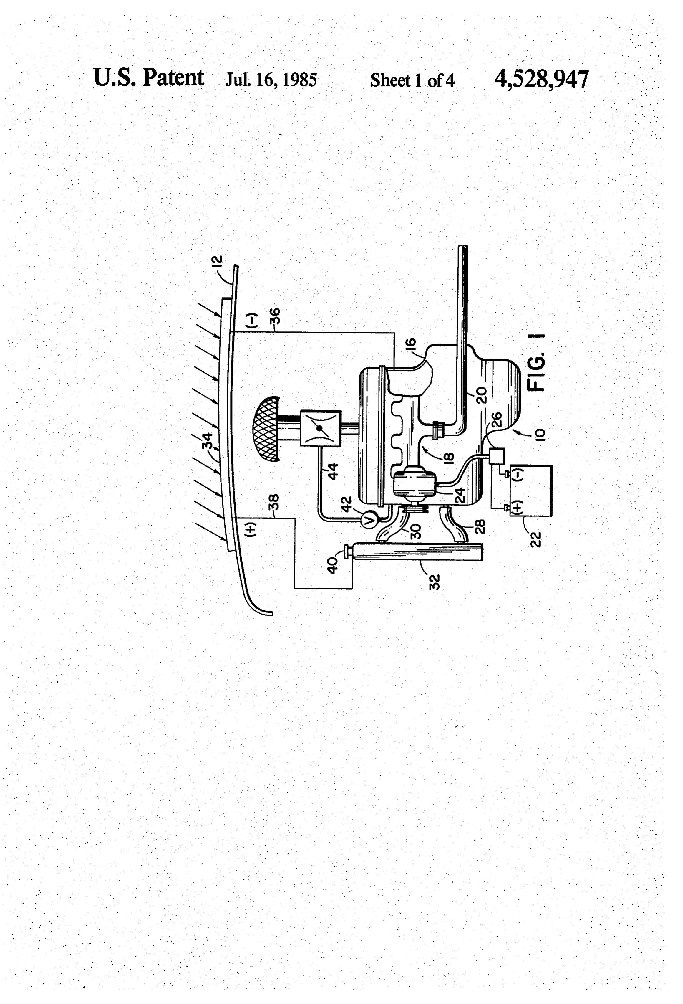
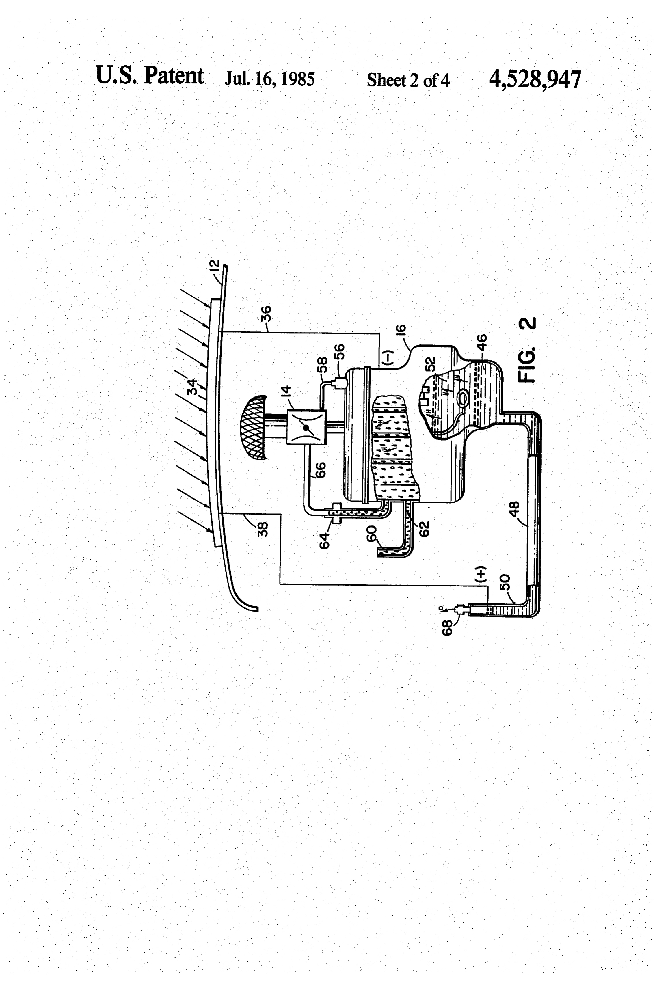
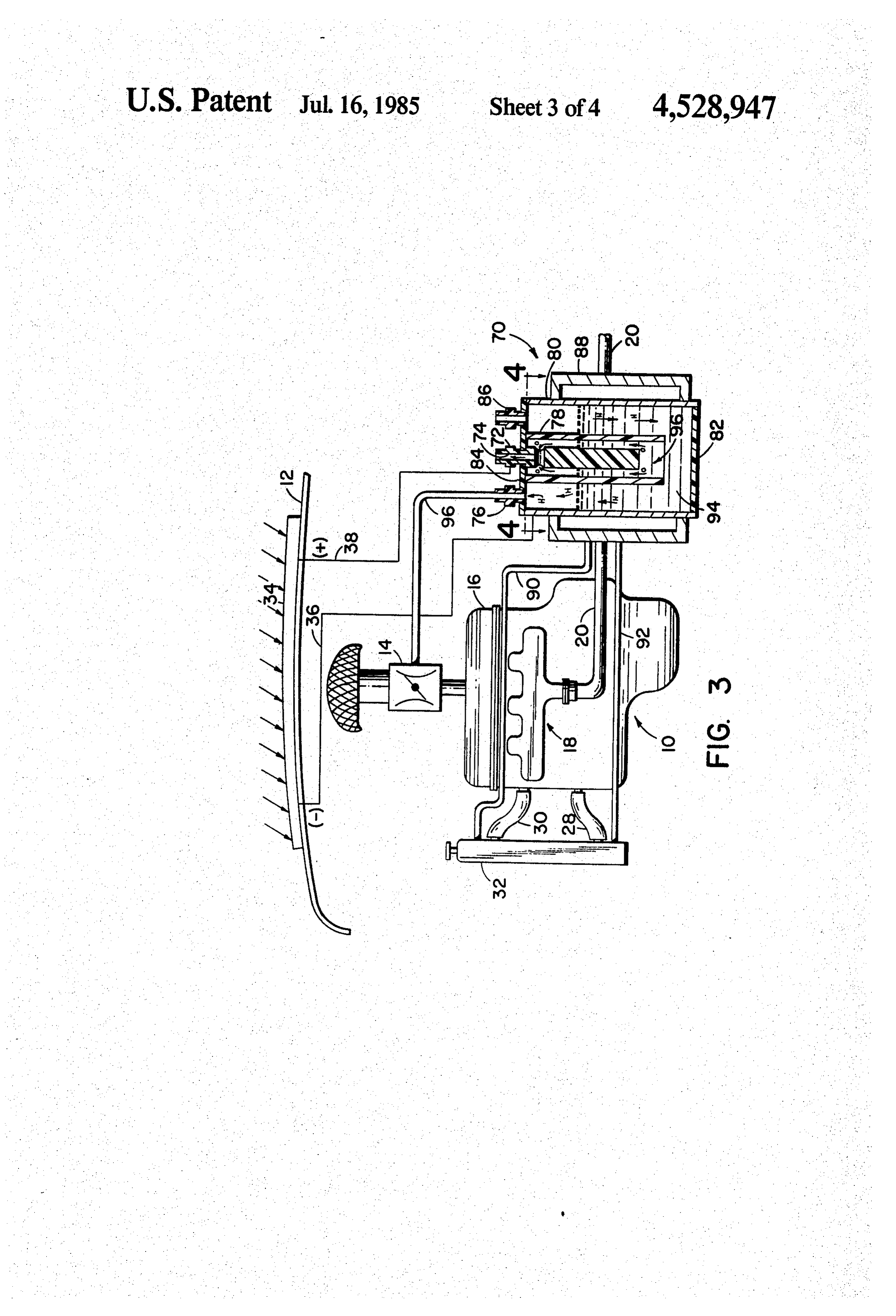
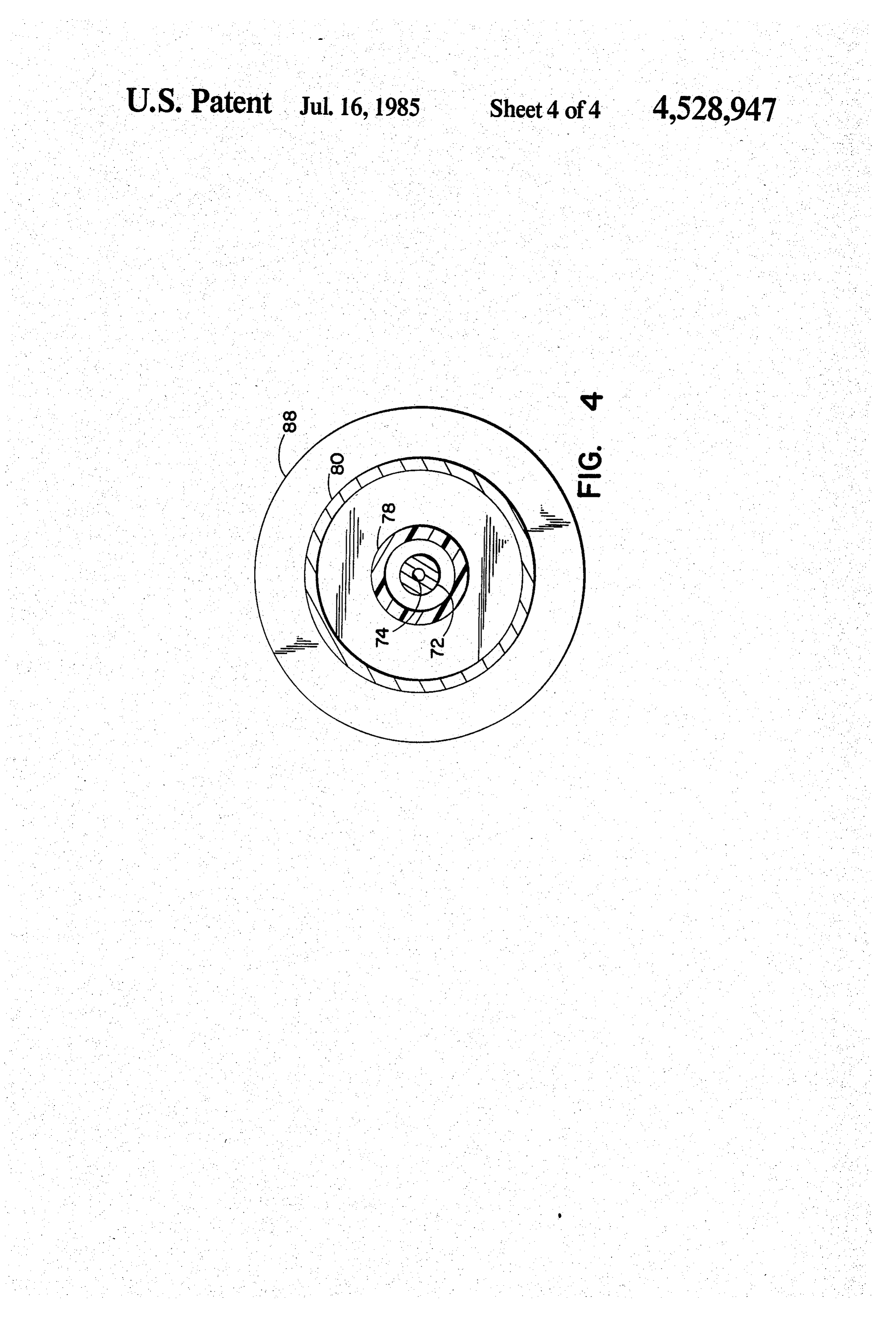
hydrogen gas when heated and a microcavity hydrogen BRIEF DESCRIPTION OF THE DRAWINGS storage supply to provide hydrogen gas to regenerate the metal hydride hydrogen supply when the metal FIG. 1 illustrates the solar oxy-hydrogen fuel burning hydride is depleted of hydrogen. In addition, the mi 40 engine of the present invention embodied in an internal crocavity hydrogen storage supply requires periodic combustion engine of a vehicle, FIG. 2 illustrates another embodiment of the inven replacement with a freshly charged microcavity hydro gen component. Thermal controls are used to control tionFIG. in an internal combustion engine, the heating and cooling of the microcavity storage sup showing3 aillustrates a third embodiment of the invention cross-sectional view of an electrolysis unit ply and the metal hydride to regulate the rate of dis 45 that may be used to produce hydrogen and oxygen charge of hydrogen. gases, spino, describes an internal combustion engine in which lineFIG. 4 is a top plan view in cross-sectional along the the fuel-air mixture is supplemented by the hydrogen and oxygen gases from an electrolysis unit. The unit is 50 DETAILED DESCRIPTION energized by the electrical generating system driven by First by way of background and referring to FIG. 1, the engine and the unit is only operative when the en FIG. 1 illustrates an internal combustion engine shown gine is running. Large amounts of current are required generally by the numeral 10 that is mounted within an to produce the preferred amount of hydrogen and oxy engine compartment of a vehicle below an overlying gen gases and consequently, the unit must be cooled by 55 body panel 12. The engine 10 is conventional to the the engine coolant to dissipate the large amounts of heat extent that is has a carburetor 14 for producing a mix generated to prevent electrolyte boil-off. The unit is ture of fuel and air that is injested into the cylinders also further pressurized to minimize boil-off.
The present invention provides an improved oxy within the engine casing 16 where the mixture is burned to produce power. Exhaust gases from the combustion hydrogen fuel burning vehicle in which the electrolysis 60 process are discharged through an exhaust system 18 unit is aided by solar cells to generate supplemental including an exhaust pipe 20. The electrical system gases that are stored while the vehicle is not in use. providing power for the engine and assessories includes Another feature of the present invention eliminates the a battery 22, a generator or altenator 24 driven from the need for a conventional cooling system associated with engine, and a regulator and control unit 26 to operate the fuel burning engine because heat generated by the 65 and maintain the electrical charge in the battery. The combustion and electrolysis processes is absorbed by engine casing 16 or block includes a jacket surrounding the electrolyte to enhance the formation of hydrogen the cylinders and the jacket is connected through con and oxygen gases. Still another feature of the invention duits 28,30 with a cooling means such as a radiator 32.
Page 7scan →
All of the above components of the engine 10 are con electrolytes such as water. Consequently, since the heat ventional parts of the power plants found in most trucks is absorbed by the hydride the electrolyte will not boil and automobiles as shown, for example, in U.S. Pat. No. off during electrolysis and cooling of the electrolysis 4,271,793 referenced above. unit and accordingly the electrolyte is not required. A radiant energy collecting system comprised by a The hydride used in the electrolyte of the present plurality of solar cells 34 is mounted with the cells in an invention is formed in the following manner. The hy array on the body panel 12 to collect light and solar dride is produced from a reaction involving the dis energy and generate direct current. The solar cells are solving of titanium in a sulfuric acid solution having a enclosed in a sealed panel, such as a crystal sheet from concentration in the range of 7 to 38%. A platinum which electrons are easily disassociated. The cells are 10 electrode is used as the anode and a titanium electrode interconnected to produce a voltage of approximately 2 is used as the cathode with the titanium electrode pro volts between a negative output terminal 36 and a posi viding the titanium for the solution. An electrical cur tive output terminal 38. The amperage between the two rent is supplied at 12 volts to start the reaction and once terminals when a load is connected is proportional to the reaction is started it is self-sustaining and electrical the number of panels. The solar cells are utilized to 15 current is no longer needed. The titanium dissolves in provide power for an electrolysis unit that generates the sulfuric acid solution until saturation occurs, at hydrogen and oxygen gases. which time the titanium-sulfate solution becomes black. Considering now the invention and still referring to An organic hydrocarbon compound, such as isopropyl FIG. 1, the electrolysis unit for producing hydrogen alcohol having a 70% concentration, is added to the and oxygen gases comprises the engine casing 16 and 20 black solution in the proportion one part alcohol to five the engine cooling system or radiator 32. An electrode, parts of the titanium-sulfate solution. A second voltage for example, the negative electrode of the electrolysis of approximately 2 volts is then applied across the unit is formed by the engine casing 16 and is connected anode and cathode to start electrolysis to produce hy to the negative terminal 36 of the solar cells 34. The drogen which is absorbed by the titanium-sulfate solu other electrode, the positive electrode of the unit, is 25 tion and causes a white precipitate to form and to turn formed by the radiator 32 which is of a noble metal to the black titanium-sulfate solution clear. The titanium, withstand corrosion and is correspondingly connected carbon and hydrogen ions are now bonded together in to the positive terminal 38 of the solar cells 34. The the white precipitate which is the hydride. When the engine coolant itself is replaced by an electrolyte and hydride is used in the electrolyte and is heated above electrically insulating fluid conduits such as rubber 30 150 Farenheit, hydrogen is expelled and the solution hoses 28.30 connect the radiator 32 to the jacket sur begins to turn black again. The solar cells 34 generate a rounding the cylinders in engine casing 16. The electro voltage of approximately 2 volts in magnitude and the lyte provides an electrical current path between the electrical current produced is used to repeat the elec positive and negative electrodes. During electrolysis, trolysis process to continuously replenish the hydride oxygen ions flow to the positive electrode and form an 35 with hydrogen. Therefore, the hydride may be regener oxygen gas in the radiator 32, and the oxygen is bled ated without the necessity of a prolonged fuel stop. through a valve 40 on the radiator 32 to the atmosphere. FIG. 2 shows another embodiment of the present Hydrogen ions flow to the negative electrode and form invention in an internal combustion engine wherein the hydrogen gas in the engine casing 16. The hydrogen gas electrolyte 46 is contained in the oil pan of the engine is collected within the upper portion of the casing 16 casing 16 and the casing is connected by an electrically which is connected by a valve 42 and a conduit 44 insulating conduit 48 to a reservoir means 50. The en connecting the valve 42 to the carburetor 14 to provide gine casing 16 and reservoir means 50 form an electroly hydrogen gas to the carburetor 14. sis unit with the engine casing being the negative elec The electrolyte used with the present invention in trode and the reservoir means being the positive elec cludes a hydride for absorbing and storing hydrogen 45 trode. An array of solar cells 34 is mounted on a body generated by the current produced by the solar cells 34 panel 12 for producing electrical current from sunlight when the engine is not in operation and consuming to power the electrolysis unit. The positive terminal of hydrogen gas fed to the carburetor 14. The hydride also the solar cells 34 is connected via lead 38 to the reser absorbs heat produced by the combustion process when voir means 50 which functions as an anode and the the engine is in operation to promote the disassociation 50 negative terminal of the solar cells is connected via lead of hydrogen stored in the hydride. Consequently, since 36 to the engine casing 16 which functions as the cath the heat of combustion is absorbed by the hydride, a ode. The electrolyte includes a hydride as described conventional cooling system is not necessary. There above for absorbing and storing hydrogen generated by fore, the water pump and conventional radiator associ the electrolysis process. The hydrogen produced by ated with the cooling system can be eliminated and the 55 electrolysis and the hydrogen released from the hydride radiator 32 is replaced with a reservoir means to hold a when the hydride is heated bubbles through the engine supply of electrolyte and to function as one of the elec oil into the upper portion of the engine casing 16 where trodes. The hydride in the electrolyte also functions as the hydrogen gas collects and is fed through a positive a reserve source of hydrogen to supplement the hydro ventilation crankcase (PVC) valve 56 which is con gen produced by electrolysis when the engine is in 60 nected to the carburetor 14 by conduit 58. The oxygen operation and consuming the hydrogen gas produced. gas generated during the electrolysis process is vented The hydride is thermally activated, that is, hydrogen is to the atmosphere through a vent 68 connected to the more easily disassociated from the hydride when heat is reservoir means 50.
added. Preferably, the hydride has an optimum hydro Because the hydride absorbs the heat of combustion gen disassociation at a temperature of approximately 65 and the engine may be operated without a conventional 150 Fahrenheit to permit heat to be absorbed by the cooling system it is possible to feed the fuel used in the hydride to produce a sufficient quantity of hydrogen fuel-air mixture through the jacket surrounding the and still remain well below the boiling point of most cylinders in the engine casing 16 through an inlet 60,
Page 8scan →
Hydrogen released from the hydride and produced by in several preferred embodiments; however, numerous electrolysis is also bubbled through the engine fuel 62 modifications and changes may be had without depart flowing through the jacket where the fuel absorbs the ing from the spirit of the invention. Therefore, the in hydrogen and becomes more volatile. The fuel 62 is fed vention has been described by way of illustration rather through a valve 64 to the carburetor 14 via a conduit 66. than limitation.
Turning now to FIGS. 3 and 4, an electrolysis unit I claim:
also known as an electrolytic cell for producing hydro 1. A solar oxy-hydrogen vehicle comprising in com gen and oxygen gases for use with a fuel burning engine bination:
such as an internal combustion engine is shown gener an internal combustion engine including a fuel system ally by the numeral 70. An internal combustion engine is O delivering fuel and air for the combustion process; shown generally by the numeral 10 and is similar to the an electrolyte;
engine described in the above referenced patent. The an electrolysis unit for producing hydrogen and oxy electrolysis unit 70 is preferably cylindrical in shape gen gases from said electrolyte and connected having walls 80 which form one of the electrodes, that through conduit means with the fuel system for electrode being the cathode and producing hydrogen 15 feeding the gases into the engine for combustion gas and the second electrode 72 being the anode and with the fuel and air;
producing the oxygen gas. A source of electrical cur an array of solar cells for the production of electrical rent such as solar cells 34 mounted on a body panel 12 current from light, the solar cells being connected provide current to the electrolysis unit 70. The anode 72 with said electrolysis unit for sending current is connected to the positive terminal of the solar cells 34 20 through the unit and producing the hydrogen and by lead 38. The cathode 80 is connected to the negative oxygen gases fed to the fuel system, and terminal of the solar cells 34 by lead 36. The solar cells said electrolyte including a hydride comprising are connected in such a manner to produce a voltage of titanium dissolved in a 7% to 38% concentrated not more than 2 volts across the positive and negative sulphuric acid solution to form a titanium-sulfate terminals 36,38. Limiting the magnitude of the voltage 25 solution which is reacted with an organic hydro used for electrolysis automatically limits the amount of carbon compound whereby said hydride absorbs current that can flow in the electrolysis unit 70 and and stores hydrogen generated by the electrolysis accordingly any heat generated by the electrolysis pro process and absorbs heat produced by combustion CCSS. when the engine is in operation to promote the As is shown in FIGS. 3 and 4, the anode 72 extends 30 . disassociation of hydrogen stored in the hydride. into the electrolytic cell 70 through a lid 84 and the 2. A solar oxy-hydrogen vehicle as defined in claim 1 anode 72 is substantially coaxial with the cylinder wall wherein said titanium-sulfate solution is reacted with 80. A bottom 82 and the lid 84 are fabricated from a isopropyl alcohol having a 70% concentration, said non-conductive, non-corrosive material such as plastic alcohol being mixed with said titanium-sulfate solution to withstand corrosion and prevent current from flow 35 in the proportion one part alcohol to five parts titanium ing in a path other than that provided by the electrolyte. sulfate.
A sleeve 78 is also fabricated from a non-conductive, 3. A solar oxy-hydrogen vehicle as defined in claim 1 non-corrosive material such as plastic and attaches to wherein said engine includes an engine cooling system the lid 84 and surrounds the anode 72. The sleeve 78 having a radiator, electrically insulating fluid carrying extends into the electrolytic cell further than the anode 40 conduits and an engine casing jacket, and wherein said 72, so that ion flow in the electrolyte 94 flows to the electrolysis unit further comprises the engine casing and cathode 80 from the anode 72 through an aperture the cooling system radiator, and the radiator and engine shown generally at 96 formed at the end of the sleeve 78 casing are connected by said electrically insulating fluid opposite the end attached to the lid 84. A relatively carrying conduits with the cooling fluid being the elec smaller ionic discharge area from the anode 72 to a 45 trolyte, the engine casing forming one of the electrodes much larger ionic receptive area such as the cathode 80 and producing one of the hydrogen and oxygen gases, also minimizes heat generated in the electrolysis process the radiator forming the other of the electrodes and and prevents electrolyte boiloff in the electrolytic cell producing the other of the gases.
without the need of external cooling. 4. A solar oxy-hydrogen vehicle as defined in claim 3 Venting means 74 in the anode 72 allow the generated 50 wherein said radiator is constructed of a noble metal. oxygen gases to escape to the atmosphere. A vent 76 in 5. A solar oxy-hydrogen vehicle as defined in claim 1 the lid 84 is connected by a conduit 96 to the carburetor wherein said electrolysis unit comprises: 14 to deliver hydrogen gas formed and collected at the container means having sides, a lid and a bottom for cathode 80. An inlet valve 86 is provided in the lid 84 holding a quantity of electrolyte, the lid and bot for filling the electrolytic cell 70 with electrolyte 94. 55 tom being made of a non-corrosive and electrically A heat exchanger means 88 surrounds the electrolytic non-conductive material and the sides forming one cell 70 and transfers heat to the electrolyte to promote of the electrodes for producing one of the hydro the production of hydrogen. The heat exchanger is gen and oxygen gases;
connected, for example, to the cooling system 32 and second electrode means extending through the lid the cooling fluid is circulated through conduits 90,92 60 transversely into said container means for a first attached to the heat exchanger means 88 to transfer predetermined distance for producing the other of heat. Heat generated by the combustion process and the gases;
expelled as exhaust gas may also be in communication means for applying an electrical potential across said with the heat exchanger means 88 to provide a source of first and said second electrode means; heat to the electrolytic cell 70 to promote the produc 65 shielding means surrounding said second electrode tion of hydrogen and oxygen gases. means and having one end attached to the con A solar oxy-hydrogen fuel burning vehicle embody tainer lid and the other end open and extending into ing the present invention has been described and shown said container for a second predetermined distance, 9 said second predetermined distance being greater electrically insulating conduit means for carrying a than said first predetermined distance, said shield liquid;
ing means further having a fixed, spatial relation reservoir means for holding a supply of said electro ship with said first and second electrode means to lyte and connected to the engine crankcase by said form a first channel between said shielding means 5 insulating conduit means with the electrolyte flow and said first electrode and a second channel be ing between the engine crankcase and said reser tween said shielding means and said second elec voir means through said insulating conduit means; trode such that said second channel is smaller than an electrolysis unit for producing hydrogen and oxy said first channel whereby the ion flow in the elec gen gases from said electrolyte wherein said elec trolyte to said electrodes is limited so that heat 10 trolysis means comprises said reservior means and produced by electrolysis is controlled to prevent the engine crankcase, said reservoir means forming electrolyte boil off, and one of the electrodes and producing one of the venting means associated with said first and said sec hydrogen and oxygen gases, the engine crankcase ond electrode means for allowing the hydrogen forming the other of the electrodes and producing and oxygen gases produced during electrolysis to 15 the other of the gases, and be released from said electrolysis unit. an array of solar cells integrated into the body panels 6. A solar oxy-hydrogen vehicle as defined in claim 5 of the vehicle for the production of electrical cur further including a heat exchanging means associated rent from light, the cells being connected to pro with said electrolysis unit for transferring heat to said duce an electrical current at a potential of not more unit to promote the production of hydrogen and oxygen 20 than two volts and also connected with said elec gases produced by electrolysis. trolysis means for energizing said electrolysis 7. A solar oxy-hydrogen vehicle as defined in claim 5 means and producing the hydrogen and oxygen wherein the means for applying an electrical potential gases, across the first and second electrodes has an output 9. In a solar oxy-hydrogen vehicle the combination as voltage not more than two volts to limit the electrical 25 defined in claim 8 wherein said electrolyte includes a current flowing in the electrolyte so that the heat pro hydride for absorbing and storing hydrogen produced duced by electrolysis is limited whereby cooling of the from the current of the solar cells passing through said electrolysis unit is not required. electrolysis unit when the engine is not in operation and 8. In a solar oxy-hydrogen vehicle, the combination for capturing the heat of combustion when the engine is comprising: 30 in operation to facilitate the release of hydrogen stored an internal combustion engine including a fuel system in the hydride.
delivering fuel and air for combustion, a crankcase, 10. In a solar oxy-hydrogen vehicle the combination a first conduit means connected to the fuel system as defined in claim 8 wherein said first conduit means and the engine crankcase for delivering gases in the connecting the engine crankcase and the fuel system is crankcase to the fuel system; 35 a positive crankcase ventilation valve. an electrolyte; ck sk sk ck ck
Provenance
- Collection
- Patents citing this work
- Pages
- 9
- Method
- pdftotext (the PDF's own text layer) + pdftoppm 300dpi page scans
- Patent office record
- patents.google.com →
- Source
- Google Patents citing-documents table
- Assignee
- Uni-Energy Systems, Inc.
- Published
- 1985-07-16
- Transcribed from
- patentimages.storage.googleapis.com →