

patent · US4543733A
Fluidity of a continuous transverse flow magnetically stabilized fluidized bed
1 October 1985
Text
Page 1scan →
United States Patent (19)
Siegell et al.
54 fluidity of a continuous
Transverse flow magnetically
Stablized fludzed bed
75 Inventors: Jeffrey H. Siegell, Westfield; Costas A. Coulaloglou, Morristown, both of
73 Assignee: Exxon Research and Engineering Co., Florham Park, N.J.
52 U.S. Cl. ........................................... 34/1; 201/31;
58 Field of Search ............... 209/454, 466, 467, 474,
1,291,137 l/1919 Reed .................................... 209/474 3,471,016 10/1969 Eveson et al... . . 209/474 X
4,132,005 1/1979 Coulaloglou ... 34/1 X 4,136,016 1/1979 Rosensweig .... 422/139
4,367,153 1/1983 Seiver ......... ... 34/1 4,368,131 1/1983 Rosenweig . ... 34/1 4,368,132 l/1983 Seiver ....................................... 34/1
Foreign patent documents
Other publications
Kamiyama et al., Bull, JSME, vol. 22, No. 171, pp.
Solds
Feed mxture
Components a, b, c, d
Von W. Isler, Zement-Kalk-Gips, No. 10/1960, pp.
Modern Materials Handling, vol. 22, Iss. 9, pp. 42-44,
Shinohara et al., J. of Chen. Engineering of Japan, vol. 5,
Shinohara et al., J. of Chem. Engineering of Japan, vol. 6,
D. Martin, Process Engineering, p. 39, (Jul. 1975). W. Stegmaier, Fordern and Heben, vol. 26, No. 6, pp.
C. Woodcock, et al., Intern. Powder and Bulk Solids and Processing, Proceeding of Technical Progress, Philadel
Primary Examiner-Frank W. Lutter
Assistant Examiner-William Bond
Attorney, Agent, or Firm-John W. Ditsler; E. Thomas Wheelock
In a magnetically stabilized fluidized bed in which the bed particles continuously move transverse to the flow of the fluidizing fluid, the bed particles have increased fluidity when the bed is operated at or substantially near the locus of transition between the bubbling and stabi lized regimes of said bed. More specifically, the particu late bed comprising a transverse flow magnetically stabilized fluidized bed process has greater fluidity when the bed is operated such that the ratio of the difference between the transition velocity and the oper ating velocity to the difference between the transition velocity and the normal minimum fluidization velocity ranges between -0.1 and -0.5. The increased fluidity facilitates the movement of solids within a vessel as well as the transfer of solids to other vessels. Stabilization of the bed, which prevents and substantially eliminates fluid bypassing and solids backmixing, may be effected externally by an applied magnetic field or internally by permanently magnetized magnetic particles within the bed. The present invention has application to a wide variety of processes (particularly separation and filtra tion-processes) wherein small size fluidizable, absorbent particles can be used without encountering the high pressure drops normally associated with non-stabilized beds.
21 Claims, 8 Drawing Figures
Soios
mo out
Drawings
Page 2drawing sheetscan →
Page 3scan →
O oooo (otoc, ooooooo
Top view
Oooo o oo oooooooo
Solids
Solids flow
Horizontal
Gas flow
or = BED TILT ANGE y = ANGLE OF SOLIDS FLOW
Page 4drawing sheetscan →
Page 5drawing sheetscan →
Page 6drawing sheetscan →
Page 7scan →
magnetic effects, and (b) an upper limited defined by the
FLUIDITY OF A CONTINUOUSTRANSVERSE superficial fluid velocity (UT) required to cause time FLOW MAGNETICALLY STABILIZED varying fluctuations of pressure difference through the FLUIDZED BED stabilized bed during continuous fluidization in the pres ence of the applied magnetic field. In U.S. Pat. No.
FIELD OF THE INVENTION 4,115,927, Rosensweig discloses that the stably fluidized The present invention relates to a process for the solids resemble a liquid such that solids transport is continuous transverse flow of fluidized solids in mag facilitated while the pressure drop is limited to that of a netically stabilized fluidized beds. More particularly, fluidized bed. Also the backmixing normally associated the invention relates to improving the fluidity of the O with conventional fluidized bed processes is absent. particulate bed during a continuous transverse flow Furthermore, while U.S. Pat. No. 4,115,927 suggests magnetically stabilized fluidized bed process by operat the possibility of transporting the solids from the con ing said bed at or substantially near the locus of transi taining vessel (see column 8 lines 58-59 and column 21 tion between the bubbling and stabilized regimes. lines 17-24), none of the experiments involved continu 5 ous throughput of bed solids. In addition, neither
BACKGROUND OF THE INVENTION Rosensweig nor Filippov described operations near the Numerous investigators have studied the influence of locus of transition between the bubbling and stabilized magnetization on the dynamics of fluidized solids in regions in beds having continuous solids addition and batch bed operations. An early account of this phenom removal. Therefore, the boundaries of the regions de enon was reported by M. V. Filippov Applied Magne 20 fined by Rosensweig and by Filippov do not concern tohydrodynamics, Trudy Instituta Fizika Akad. Nauk, processes where solids are added and removed continu Latviiskoi SSR 12:215-236 (1960): Zhurnal Tekhniches ously.
Koi Fiziki, 30, (9): 2081-1084 (1960); Izvestiva Akad. More recently, U.S. Pat. No. 4,247,987, the Belgian Nauk, Lativvskoi SSR, 12 (173): 47-51 (1961); Izvestiya counterpart of which was granted on Mar. 29, 1981 as
Akad. Nauk, Latviiskoi SSR, 12: 52–54 (1961); and Belgian Pat. No. 885,390, described the countercurrent Aspects of Magnetohydrodynamics and Plasma Dy operation of a magnetically stabilized bed with continu namics, Riga (1962), Izvestiya Akad. Nauk, Latviiskoi ous solids addition and removal at or substantially near SSR, pp. 637-645. Subsequent investigators have de the locus of transition between the bubbling and stabi scribed the influence that magnetization exerts on pulsa lized regions of the bed in order to increase bed fluidity. tions, heat transfer, structure, and other characteristics 30 However, patentees disclose only countercurrent oper of magnetized and fluidized solids in batch bed opera ations-no mention is made of solids transport trans tions. A partial review of such studies has been pres verse to the flow of the fluidizing fluid. ented by Bologa and Syutkin Electron Obrab Mater, 1:
37-42 (1977). Ivanov and co-workers have described SUMMARY OF THE INVENTION some benefits of applying a magnetic field to fluidized 35 Accordingly, the present invention is directed to a ferromagnetic solids during ammonia synthesis and method of increasing the fluidity of the particulate bed noted some of the bed characteristics during said syn thesis see British Pat. No. 1,148,513 and numerous in a continuous transverse flow magnetically stabilized fluidized bed process. More particularly, in a magneti publications by the same authors, e.g., Ivanov et al, cally stabilized
Kinet. Kavel, 11 (5): 1214-1219 (1970); Ivanov et al, 40 able particles isbed wherein a bed of fluidized magnetiz Zhurnal Prikladnoi Khimi, 43, 2200-2204 (1970); Iva izing fluid passing upwardwithcontacted a gaseous or liquid fluid through said bed but trans nov et al., Zhurnal Prikladnoi Khimni, 45: 248-252 verse (i.e., non-parallel) to the flow of the bed particles, (1972); Ivanov et al, Chemical Industry, 11, 856-585 said particulate bed will have greater fluidity (1974); Shumkov et al., Zhurnal Prikladnoi Khimi, 49 bed is operated at or substantially near the when locus the (11): 2406-2409 (176). In addition, various means for 45 transition between the bubbling and stabilized regimes. operating magnetic fields to stabilize a bed of magnetiz As used herein, the expression "substantially near the able solids have been disclosed in U.S. Pat. Nos.
3,440,731; 3,439,899; 4,132,005 and 4,143,469; and Bel locus ratio of transition' refers to maintaining the fluidity (or the difference between the transition velocity
Recently, R. E. Rosensweig reported a number of 50 and the operating velocity to the difference between the features relating to magnetically stabilized fluidized transition velocity) velocity and the normal minimum fluidization between -0.1 and --0.5. The fluidity ratio magnetizable solids and provided a systematic interpre tation of the phenomenon Science, 204:57-60 (1979), may be expressed mathematically as:
chesi et al, Proc. of the 10th World Petroleum Congress, 55
Bucharest, Romania, 1979, 4, Heyden and Sons, Phila
4,136,016). These publications noted the quiescent, where UT is the superficial fluid velocity required to fluid-like state of the magnetically stabilized fluidized cause time-varying fluctuations of pressure difference bed (MSB), particularly a bed totally free of bubbles or 60 through the bed in the presence of a magnetic stabiliz pulsations when subjected to a uniform magnetic field ing means, Unafis the normal minimum fluidization su applied colinear with the flow of the fluidizing fluid. perficial fluid velocity required to fluidize the bed of Bed stabilization results in a non-bubbling fluid state magnetizable particles in the absence of magnetic ef having a wide range of operating velocities (denoted as fects, and Uo is the actual operating superficial fluid superficial fluid velocities) which range between (a) a 65 velocity.
lower limit defined by the normal minimum fluidization The magnetic stabilizing means, which serves to sta superficial fluid velocity (Uni) required to fluidize the bilize the bed, should be of sufficient strength to sup bed in the absence of the applied magnetic field, i.e. press particle backmixing within the bed but below that 8 which would cause excessive particle to particle attrac suppress substantial bubble formation and fluid bypass tive forces. Similarly, the superficial velocity of the ing in the bed.
fluidizing fluid should be in excess of the normal mini Magnetically stabilized fluidized beds have the ap mum fluidization superficial velocity in the absence of pearance of expanded fixed beds with essentially no magnetic effects, but below the superficial velocity 5 gross solids backmixing and essentially no fluid bypass which will cause solids backmixing. ing such as bubbling in gas fluidized beds and roll-cell
Brief description of the drawings
behavior in liquid fluidized beds. The application of the magnetic field allows superficial fluid flow rates of 2, 5,
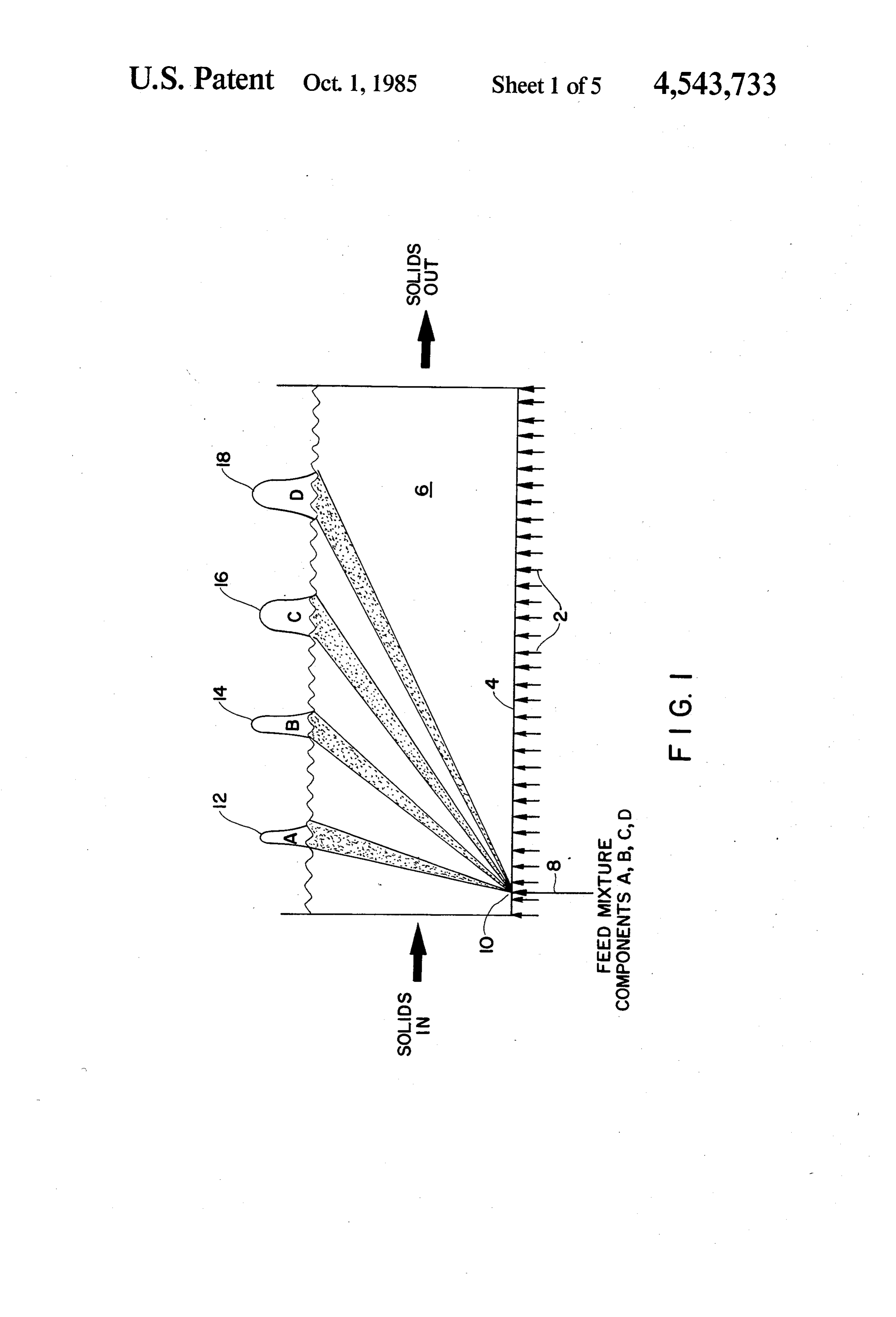
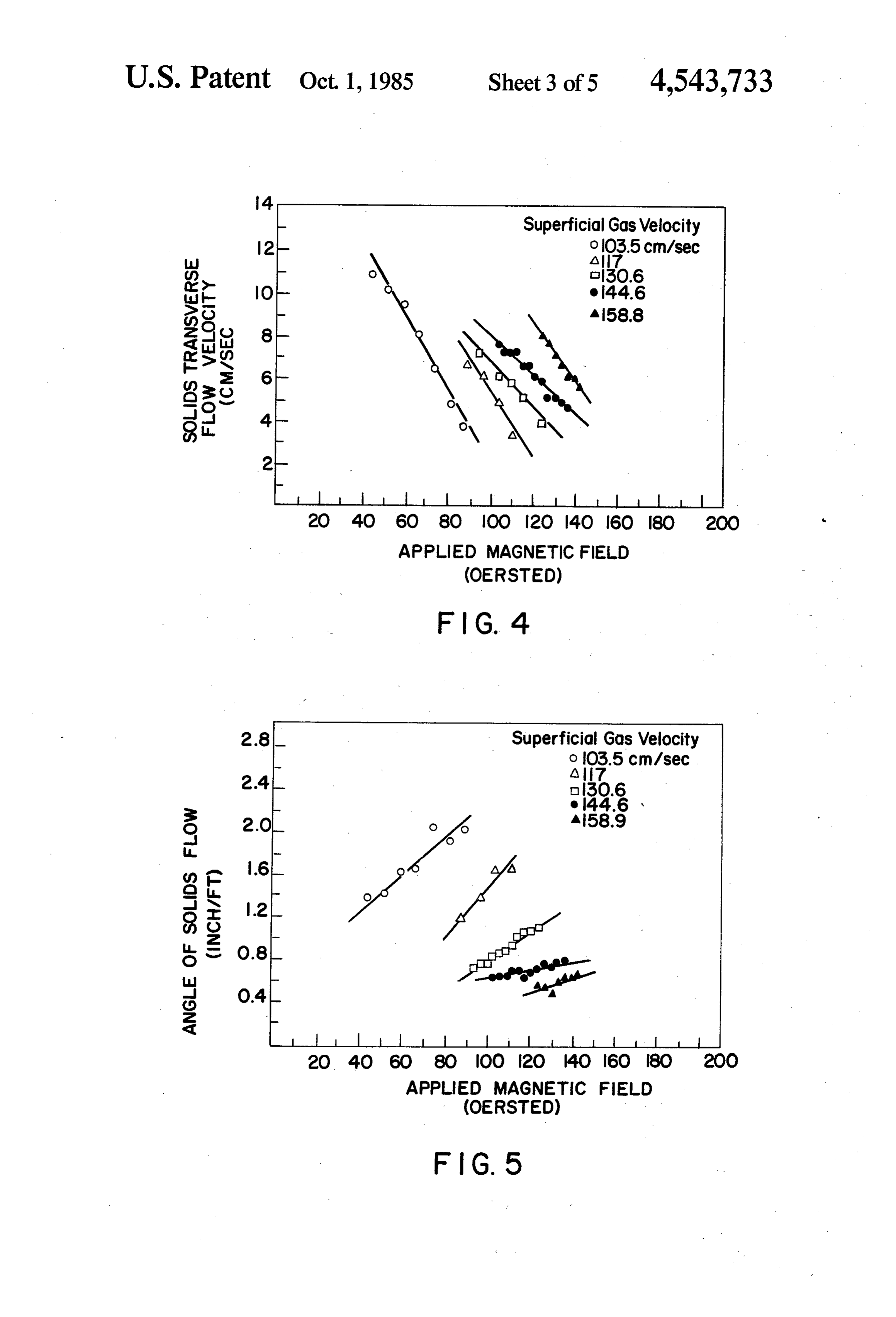
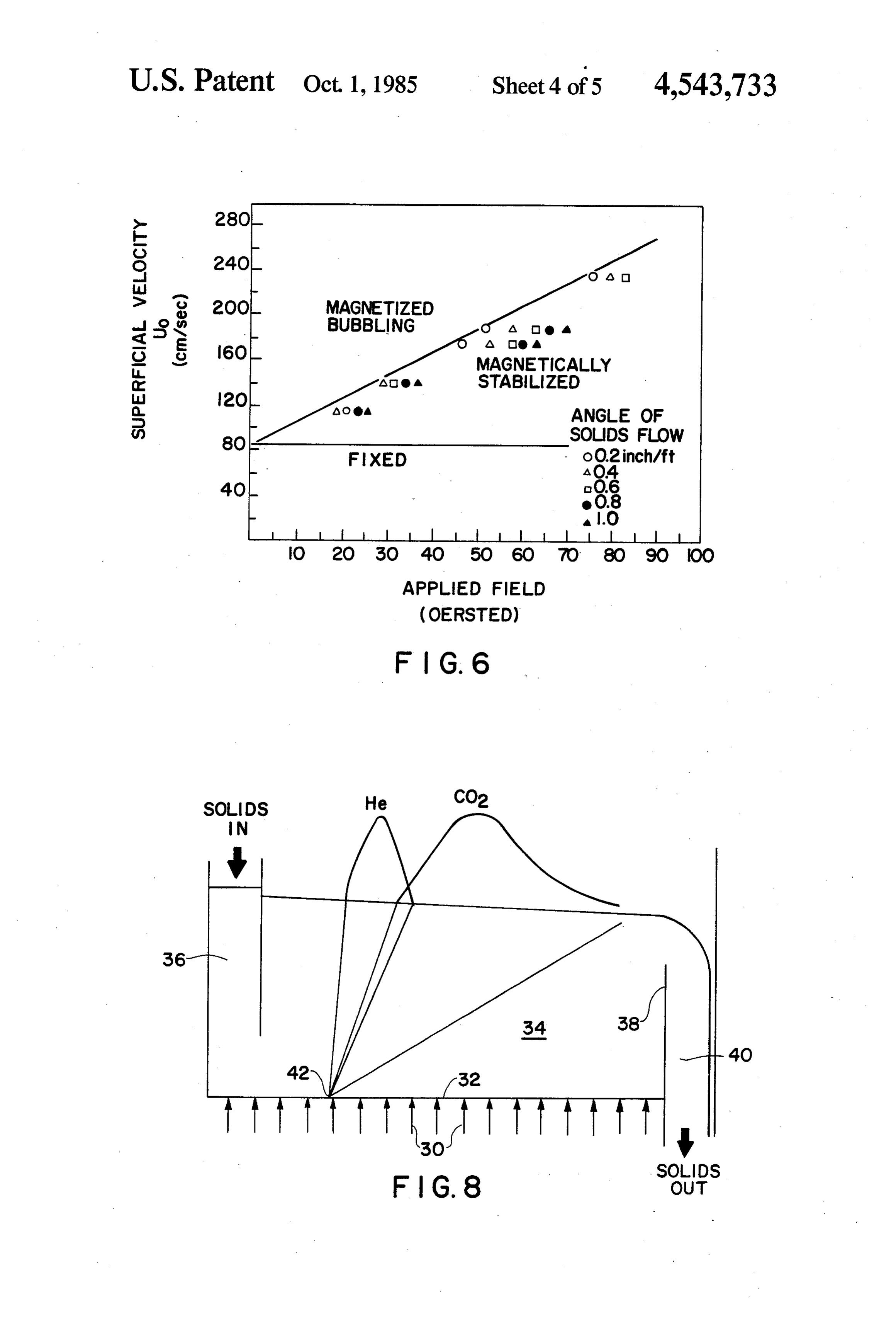
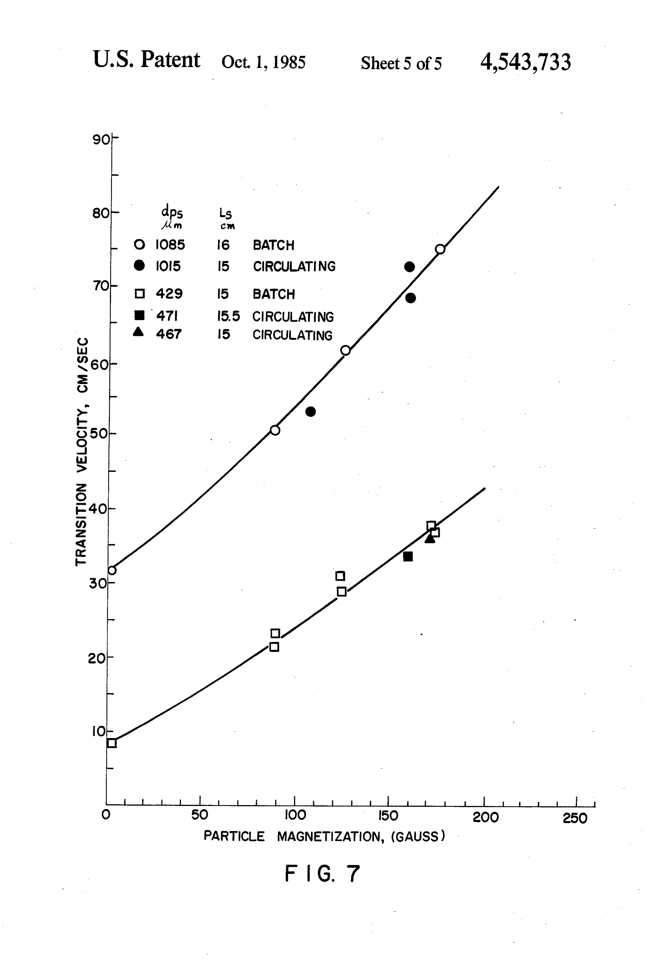
FIG. 1 illustrates the use of a transverse flow magnet O 10 or more times the flow rate of the fluidized bed at ically stabilized fluidized bed in continuous chromato incipient fluidization in the absence of the magnetic graphic separations. field, along with the substantial absence of gross solids FIG. 2 illustrates a simplified diagram of the top and backmixing and fluid bypassing. As the superficial fluid side view of the transverse flow magnetically stabilized velocity is increased, the pressure drop through the bed fluidized bed experimental apparatus. is similar to that which would be expected from a nor FIG. 3 illustrates the flow of solids and the angles 15 mal fluidized bed not subjected to an applied magnetic associated therewith in a transverse flow magnetically field-the pressure drop increases to a value corre stabilized fluidized bed. sponding to the ratio of bed weight to cross sectional FIG. 4 illustrates the effect of applied magnetic field area at the minimum fluidization velocity, and then and superficial gas velocity on solids transverse flow 20 remains relatively constant as the fluid velocity is in velocity in transverse flow magnetically stabilized fluid creased. This stably fluidized bed condition persists ized beds. even as the solids are continuously added to and re FIG. 5 illustrates the effect of applied magnetic field moved from the contacting vessel.
and superficial gas velocity on the angle of solids flow An important feature of the present invention is that in transverse flow magnetically stabilized fluidized 25 the fluidity of a bed of magnetically stabilized fluidized beds. particles continuously decreases from the fluidity at the FIG. 6 illustrates increased solids fluidity in trans bubbling or transition fluidization velocity as the mag verse flow magnetically stabilized beds near the transi netic field is increased above, or the superficial fluid tion locus. velocity is decreased below, the value at transition, FIG. 7 illustrates the effect of solids circulation on Thus, in the case of moving beds, it is desirable to oper transition superficial velocity in transverse flow mag ate close to the locus of transition between the stable, netically stabilized fluidized beds. non-bubbling bed and the bubbling regime in order to FIG. 8 illustrates a continuous chromatographic sep take advantage of the increased fluidity. Transverse aration using a transverse flow magnetically stabilized flowing stabilized beds which are operated close to UT exhibit a non plug flow solids velocity profile in the vertical direction in the absence of a solids flow control
DETAILED DESCRIPTION OF THE ling weir at the bed exit. As disclosed in copending INVENTION application Ser. No. 345,046 filed on the same date The present invention relates to a method of improv herewith, transverse flowing stabilized beds which are ing the fluidity of a stabilized fluidized bed of magnetiz 40 operated further away from UT exhibit essentially plug able particles during the transverse flow contacting of flow; i.e., essentially a flat vertical velocity profile. said particles with an upward moving fluidizing fluid by Deviations from plug flow profile when the beds are subjecting said bed to a magnetic stabilizing means at a operated in the more fluid region may be reduced or superficial fluid velocity and a particle magnetization substantially eliminated by proper design of a solids such that the fluidity ratio ranges between -0.1 and 45 flow weir at the bed exit.
--0.5, preferably between -0.05 and -- 0.2 and more The fluidity of the bed can be determined by measur preferably between -0.01 and +0.1. The magnetic ing the angle of repose of the bed particles at given stabilizing means may be internal using permanently superficial fluid velocities and applied magnetic fields. magnetized particles (such as are described in U.S. Pat. The data in Tables II, III and IV hereinafter show that No. 4,261,101, the entire disclosure of which is incorpo 50 bythe increasing the applied magnetic field or decreasing superficial gas velocity from the transition point rated herein by reference) or external using an applied magnetic field. While the magnetic stabilizing means increases the angle of repose. Thus, to obtain increased employed may be either internal or external (with exter bed fluidity, the stabilized fluidized bed should be oper nal being preferred), the present invention will be de ated at low applied magnetic fields or high fluid veloci scribed hereinafter with respect to the use of an exter 55 ties (i.e., as close to transition as possible). The induced nally applied magnetic field, most preferably a uniform magnetization of the particles should be insufficient to applied magnetic field having a substantial component cause excessive particle to particle attractive forces in along the direction of the external force field (i.e. grav the bed.
ity). The magnetically stabilized bed thus described com Depending upon the specific processing objective, 60 bines in one system the principal advantages of both the present invention may be operated in the bubbling fluidized bed and fixed bed reactor systems as is summa regime (corresponding to negative valves of fluidity rized in Table I below.
ratio) or in the substantial absence of bubble formation TABLE I (corresponding to positive values of fluidity ratio). For Fluid Fixed example, the bed will normally be operated in the bub 65 Bed MSB Bed bling regime when heat transfer is desired. Usually Small particle size with low A p yes yes O however, it is preferred that the strength of the mag Absence of fluid bypassing O yes yes netic stabilizing means be maintained so as to prevent or Continuous solids throughput yes yes O
Page 9scan →
TABLE I-continued The bed particles (composites or admixtures) will Fluid Fixed typically have an average mean particle diameter rang
Bed MSB Bed ing from about 50 to about 1500 microns. The particles
Avoids solids backmixing d yes yes may be of a single size or a mixture of several size
Avoids entrainment from bed C. yes yes ranges. Similarly, the particles may be of any shape, e.g., spherical, irregular shaped or elongated.
For economy, it is desirable that the bed solids
As an example of the advantage of a magnetically achieve sufficient magnetization to stabilize the bed at a stabilized bed, the use of small particle size reduces relatively small intensity of applied magnetic field. diffusional resistance within a bed particle such that the 10 When ferromagnetic particles are placed in the mag particle (be it catalyst or sorbent) can be used more netic field, the induced magnetization is a function of effectively. At the same time, both high pressure drop the magnetic material, the geometry of the ferromag and gross fluid bypassing are eliminated. If used as a netic particle and the geometry of the bed, as is de sorbent, small particles having a magnetic component scribed in U.S. Pat. No. 4,247,987.
permit faster transfer of the sorbed species from the 15 Conventional permanent magnets, electromagnets or contacting fluid than do larger adsorbent particles, both can be employed to provide the magnetic field. thereby enabling a faster approach to equilibrium. Also The electromagnets may be energized by alternating or with magnetically stabilized beds, several steps or oper direct current, although direct current energized mag ations can be combined in the single reacting system; for netic fields are preferred. When powered by direct example, simultaneous reaction and fluid to particle 20 current with the use of solid state control or a transfor heat exchange, particulate removal plus chemical reac mer/rectifier, electromagnets are particularly desirable tion, etc. An additional advantage is that the solids can for applying a magnetic field to the bed particles and be added to or removed from the bed. Since the stabi provide an excellent method of stabilizing the fluidiza lized beds are mobile, it is possible to carry out continu tion of the bed particles in response to the flow of the ous reactions with frequent regenerations so that cata 25 fluidizing fluid.
lyst or sorbent activity can be restored rapidly in an The invention is not limited by the shape or position other vessel following a short cycle. ing of the magnet employed to produce the externally The bed may contain magnetic and non-magnetic applied magnetic field. The magnet can be of any size, materials. For example, non-magnetic particles may be strength or shape and can be placed above or below the used as admixtures or as composites with a ferromag 30 bed depending upon the solids used, the degree of stabi netic or ferrimagnetic substance. All ferromagnetic and lization required and the like. The magnets can be ferrimagnetic substances, including, but not limited to, placed within or outside the vessel and may even be magnetic Fe3O4, y-iron oxide (Fe2O3), ferrites of the employed as an integral portion of the vessel structure. form MO.Fe2O3, wherein M is a metal or mixture of The process is not limited to any particular vessel or metals such as Zn, Mn, Cu, etc.; ferromagnetic elements 35 vessel material and it can be readily adapted for use in including iron, nickel, cobalt and gadolinium, alloys of contacting vessels currently employed by industry. In a ferromagnetic elements, etc., may be used as the magne preferred embodiment, a solenoidal shaped electromag tizable and fluidizable particulate solids which are used netic is employed to surround the fluidized bed as this in admixture or composited with the non-magnetic par provides the most uniform magnetic field and conse ticles. Alternatively the nominally non-magnetic mate 40 quently the best stability throughout the bed. rial may itself contain a ferromagnetic or ferrimagnetic With proper selection of magnetic particles, the substance in its chemical or physical makeup. In this power requirement for the electromagnet field source in case, the nominally non-magnetic material exhibits mag commercial plants will be modest. Magnet power dissi netic properties. Therefore, no additional magnetic pation generates heat that may be removed using natu material need be admixed or composited with the nomi 45 ral convection air cooling. This eliminates any need for nally non-magnetic material. liquid convection cooling and attendant requirements The magnetizable particles used in the present inven for coolant treatment and recirculation. The magnetic tion must have the proper magnetizable properties (and field source may be computer designed with high confi in some instances sorption or catalytic properties). De dence to yield an applied magnetic field having a speci pending upon the application, a variety of magnetizable 50 fied intensity and uniformity.
particles may be utilized. For non-catalytic operations The strength of the magnetic field to be applied to the such as filtering and heat transfer, ferromagnetic materi fluidized solids in the contacting zone will depend on als such as 400 series stainless steels, cobalt, iron and the magnetization of the magnetizable particles and the nickel as well as natural ferrites can be used. For cata degree of stabilization desired. Particles having rela lytic or sorption applications the magnetizable materials 55 tively weak magnetic properties, e.g., some composities may be included in suitable catalyst or sorption particle and alloys, will require the application of a stronger bases such as silica, alumina or silica-aluminas. A magnetic field than particulate solids having strong method of preparing magnetizable sorption particles is magnetic properties, e.g., iron, to achieve similar stabili described in U.S. Pat. No. 4,247,987, the entire disclo zation effects. The size and shape of the solids will also sure of which is incorporated herein by reference. 60 have an effect on the strength of the magnetic field to be The weight fraction of magnetizable material when employed. The magnetization of the particles should admixed or composited with the non-magnetic material not be sufficient to cause excessive particle to particle will vary depending upon process conditions, the par attractive forces and agglomeration which would tend ticular application of the present invention and the like. to freeze or lock the particles in the bed and prevent Typically, however, the fraction of magnetizable mag 65 continuous operation. However, since the strength of netizable in the bed will be at least 10 weight percent the field produced by an electromagnet depends on the and, preferably, should range from about 25 to about 75 current strength of the electromagnet, an operator can weight percent. readily adjust the field strength to achieve the desired 10 degree of stabilization for the particular system em phase superficial fluid velocities will range from about ployed. Specific methods of applying the magnetic field 0.001 to 5 m/sec. Similarly, the solids transverse flow are also described in U.S. Pat. Nos. 3,440,731; 3,439,899; velocity can vary broadly depending upon the velocity 4,115,927 and 4,143,469; British Pat. No. 1,148,513 and of the fluidizing fluid, the geometry of the vessel, the in the published literature, e.g., M. V. Filippov, Applied solids being fluidized, etc. Generally, however, the Magnetohydrodynamics, Trudy Instituta Fizika Akad. solids velocity will range from about 0.001 to about 50 Nauk, Latviiskoi SSR 12:215-236 (1960); Ivanov et al, cm/sec.
Kinet. Kayel, 11 (5):1214-1219 (1970); Ivanov et al, A specific application of the present invention in Zhuranal Prikladnoi Khinii, 45:248-252 (1972); and R. volves removal of particulates from hot gases from a E. Rosensweig, Science, 204:57-6 (1979), the entire dis 10 pressurized fluid bed coal combustor prior to contact closures of which are incorporated herein by reference. with expansion turbines for power recovery in a com The most preferred applied magnetic field will be a bined cycle system. In such a process coal, limestone uniform magnetic field such as is described in U.S. Pat. and compressed air are fed to a pressurized fluid bed No. 4,115,927. Typically, the applied magnetic field for boiler. The hot gases from the boiler (925 C. and 950 an empty vessel will range from about 5 to about 1500 5 kPa) are transported to primary and secondary cyclones Oersteds, preferably from about 10 to about 1000 Oer to remove ash. The gases are then fed continuously to a steds. transverse flow magnetically stabilized contactor such The present invention can be utilized in a wide vari that 99-976 of the incoming particulates are removed. ety of processing configurations. For example, after The particulate-laden solids flow to a bubbling bed undergoing the continuous transverse flow contacting 20 elutriator. A small amount of air or steam is used to described previously, the magnetizable particles may be fluidize this bed and carry the flyash overhead. After removed from the contacting chamber, although the partial cooling of the elutriator gas, the particulates can removal may be intermittent. If desired, the bed parti be removed by a conventional electrostatic precipitator. cles may be recycled to the contacting chamber or be The cleaned hot gases are then fed to the turbines for air passed through said chamber in a single pass mode; e.g. 25 compression and power generation. an iron ore reduction processor or a solids drying pro The present invention also has application to the cess. As an example of another configuration, the mag continuous chromatographic separation of a multicon netizable particles may be removed continuously (or ponent feedstock as is described in U.S. Pat. No. intermittently) from a first contacting chamber and 4,443,231 filed on the same date herewith. In conven passed to a second contacting chamber for regeneration 30 tional chromatographic processes, a multicomponent prior to being recycled to the first contacting chamber. feed and a continuously flowing carrier fluid are intro These examples should be considered as illustrative duced into a column packed with an adsorbent. The only and are not to be construed as limiting the scope of adsorbent is usually a porous or granular solid while the the present invention. feed may be in either the liquid or gaseous state. The Similarly the present invention may be applied 35 components of the feed are stratified in the column by readily to a variety of processes, including but not lin selective adsorption and desorption, and exit from the ited to particulate removal of solids, sorption separation column with the carrier fluid at different times, the processes, and solids-solids separation processes. For components being least adsorbed in the column exiting example, the present invention is well suited for remov first.
ing small contaminant particulates from a fluid stream, Normally, conventional chromatographic processes especially at elevated temperatures and pressures which are batch operations since the devices and techniques are beyond the capability of commercial electrostatic employed to stimulate continuous operations (e.g. mul precipitators and baghouses. For gas phase beds, the gas tiple feed and exit points, moving baffles, rotating bubbles and bypassing which render conventional gas packed columns etc.) are cumbersome and mechani phase fluidized beds ineffective for filtration are absent. 45 cally complicated. However since only the bed solids For liquid phase fluidized beds, the roll-cell behavior move, a transverse flow magnetically stabilized bed can normally present is absent when the bed is stabilized. separate a feed into two or more components continu Compared to a settled bed of small-size solids, the ex ously without the mechanical limitations and disadvan panded structure of a magnetically stabilized bed can tages of prior art processes. In addition, feed component collect a much greater quantity of particulates without separation will be enhanced by using smaller size adsor tending to plug at the fluid inlet face. The flow proper bents particles without increasing the pressure drop ties of the solids facilitate use of a continuous solids above the weight of the bed.
flow system in which the particulate-laden solids flow FIG. 1 illustrates the use of the present invention to to another vessel for regeneration and particulates re separate a feed mixture into its components. Mixtures moval. 55 that can be separated according to the present invention The operating conditions employed in the present include mixtures of straight chain and branched chain invention will vary broadly depending upon the partic hydrocarbons, at least one C8 aromatic isomer from a ular application. In general, however, temperatures will mixture of hydrocarbons and the like. As shown range from ambient, or lower, to the Curie temperature therein, a vertically flowing carrier fluid 2 (i.e. fluidiz of the magnetic component within the bed, and pres 60 ing fluid) passes continuously through a distribution sures will range from about 1 to about 10,000 psia. The means 4 and fluidizes a magnetically stabilized bed 6 superficial velocity of the fluidizing fluid will vary de containing solid adsorbents that flow perpendicular (i.e. pending on the inclination of the distributor, the geome crossflow) to the carrier fluid. Although the solids flow try of the vessel, the particular solids being fluidized need not be perpendicular to the flow of the carrier and the like. Normally however, the superficial fluid 65 fluid, such is desired in this particular embodiment to velocity will range from about 0.0001 to about 5 m/sec. obtain a more efficient separation. A feed mixture 8 liquid phase superficial fluid velocities will range typi having at least two components (four components A cally from about 0.0001 to about 0.1 m/sec. while gas through D are shown in FIG. 1) is introduced into bed
Page 11scan →
6 at injection point 10 and contacts the adsorbent(s) rameter for the design of a magnetically stabilized bed therein for a period of time necessary to separate at least adsorber or reactor system.
a portion of one of said components from said mixture. In the following discussion, bed fluidity is character Each component of the mixture has different adsorp ized as a function of applied magnetic field and operat tion-desorption characteristics with respect to the bed ing conditions. It thus establishes the basis for operating solids. In this illustration, component A is least strongly a transverse flowing bed at or near the transition point adsorbed by the bed solids while components B, C and between the stable and bubbling regime a stable bed and D are more strongly adsorbed. Each component moves a bubbling bed.
through the bed due to the upward flow of the carrier The experiments conducted show that the angle of fluid and the transverse flow of bed solids. Thus, each O repose of the bed particles relative to that of a loosely component has a velocity vector in two directions-one packed bed can be used as a measure of bed fluidity. The is in the direction of solids movement due to adsorption angle of repose, g, is the angle the surface of a pile of thereon while the other is in the direction of the carrier solids makes with the horizontal. Depending on the fluid toward the upper surface of the bed due to desorp method of determination, various angles of repose can tion of the components from the solids. The point at 15 be defined. For example, the poured angle of repose is which a particular component exits from the upper the maximum angle of the slope of a pile of solids surface of the bed depends upon several factors includ poured from a funnel. In contrast, the tilting angle of ing the transverse flow velocity of the bed solids, the repose is the maximum angle of tilt of a bed of solids velocity of the carrier fluid and the adsorption-desorp before sloughing occurs.
tion characteristics of the bed solids. For example the 20 A characteristic feature of fluidized beds of cohesion weakest adsorbed component (component A) is not less solids (solids without interparticle forces) is that the transported significantly by the moving solids and exits angle of repose, g, decreases gradually with increasing from the upper surface of the bed close to the feed Superficial velocity, U, from its initial value, go at Us 0, injection point at location 12. The more strongly ad sorbed components (components B, C and D) pass fur 25 to zero at the minimum fluidization velocity Un?. Thus, ther downstream with the adsorbent solid and, conse quently, exit from the upper surface of the bed further (1) from the feed injection point at locations 14, 16 and 18.
Components A through D can then be recovered from the upper surface of the bed at different distances down 30 stream from the injection point along the path or flow The initial angle of repose, So, is approximately equal to direction of said bed. In a broad embodiment, at least the angle of internal friction, d, of a loosely packed bed. one product stream will be recovered from said trans Thus, Equation (1) becomes verse flowing bed along the path of said bed, said prod uct stream comprising a portion of the carrier fluid and 35 a portion of the feed mixture containing at least a por (2) tion of one of said components.
The present invention can also be applied to separate tang - ( a mixture comprising non-magnetic solids having differ ent densities by adjusting the specific gravity of the bed 40 The tangent of db is referred to as the coefficient of as is disclosed in copending application Ser. No. 345,049 interparticle friction.
filed on the same date herewith. As disclosed therein, a The decrease in the angle of repose with increasing mixture comprising non-magnetic solids having differ velocity is due to the corresponding decrease in inter ent densities is introduced into a transverse flow mag particle friction. When interparticle friction becomes netically stabilized bed. Solids which are more dense 45 very small or vanishes, the solids exhibit full liquid-like than the bed medium ideally tend to sink in the bed behavior having very small or no resistance to shear while solids which are lighter than the bed medium tend such that the angle of repose becomes zero. to float on the surface of the bed. Since two or more The decrease of interparticle friction with increasing different density fractions may be recovered according velocity is also reflected in the viscosity of incipiently to this process, the bed should be stabilized to eliminate SO fluidized beds. In these beds, the flow limit, i.e., the solids remixing. Preferably the process should be oper shear stress, to, below which the bed behaves as a rigid ated at increased bed fluidity to facilitate movement of structure, decreases with increasing superficial velocity the solids and promote rapid separation. and approaches zero at the minimum fluidization veloc ity. Below minimum fluidization, the bed is in a semi
FLOWABILITY OF MAGNETIZED SOLIDS 55 fluid state and resembles a Bingham plastic with an
The ability to remove magnetized solids from a angle of repose and a flow limit greater than zero. highly magnetized bed is important in many applica When interparticle cohesive forces are present, as in tions. With certain types of magnetizable solids, such as the case of magnetically stabilized beds, Equations (1) iron and steel, the particle-to-particle attraction leads to and (2) are not applicable. These cohesive forces, im stickiness in the bed that limits the bed fluidity in contin 60 parted by the magnetic field, alter the rheological char uous units at particle magnetization values (M) of acteristics of the magnetized solid particles and there greater than about 500 Gauss. In otherwords, the fluid fore affect the angle of repose.
ity of some magnetizable particle particulate beds de EXPERIMENTAL DETERMINATION OF creases with increasing applied magnetic field to the SOLIDS ANGLE OF REPOSE IN A point where the bed solidifies as a slug. Low fluidity can 65 MAGNETICALLY STABILIZED BED cause flow stoppage and bed "locking” which can ad versely effect the smooth operation of magnetically The poured angle of repose was determined by par stabilized beds. Hence, bed fluidity is an important pa tially filling a 7.62 cm diameter fluidized bed vessel with 12 magnetizable solids. A solenoid electromagnetic was TABLE III placed around the bed of solids so as to provide a sub- POURED ANGLE OF REPOSE stantially uniform magnetic field. The bed was fluidized Material. Magnetite by passing air through a distributor grid at the lower 5 Particle Size: 266 um portion of the vessel. Additional magnetizable solids Particle Density: 5 g/cm
Bed Height: 2.5-5.1 cm Bed Diameter: 7.62 cm were poured into the container from a funnel that was Angle of raised as the pile of solids increased to cover the 7.62 cm Applied Magneti- Veloc- Repose diameter surface. The results of several tests are shown Field, zation, ity, f3, Tan Ostereds Gauss cm/sec Degrees (8 Remarks
The tilting angle of repose was determined in a man- 8 g5 : g: 57.ec 13.7 ner similar to that described above. The vessel was O O 2.3 9 0.5 partially filled with magnetizable solids, a magnetic O O 2.3 15 0.20 - V 65 210 O 4. 0.86 UT = 43.2 cm/sec field was applied and the bed was fluidized by passing 65 210 2.8 34 0.66 air through the grid. Then the bed surface was tilted 15 65 20 22.6 25 0.46 very slowly about the horizontal axis angle without the solids sliding while the bed surface 130 380 O 45 1.0 U r = 65.8 cm/sec remained perpendicular to the direction of flow and the 130 380 O 47 1.06 walls of the vessel. When the bed surface was tilted 2 3O 380 19.3 4. O.86 beyond the maximum angle, sliding occurred. The 130 380 25.7 34 0.66 angle of the bed surface to the horizontal once the solids 30 38O 45 15 0.26 begin sliding is defined as the angle of repose. Data for 58 : g : the tilting angle of repose are shown in Table IV.
As shown therein at zero applied field, the angle of 25 repose decreases with increasing velocity and ap- TABLE IV proaches zero at the minimum fluidization velocity, TILTING BED ANGLE OF REPOSE This is in agreement with Equations (1) and (2). When Material: 33 Wt. 7, RO Stainless Steel Beads the applied field is greater than zero, the angle of repose 3O E. E.Nipig. 2. in similarly decreases with increasing velocity but ap- Bed Height:3.5 cm Bed Diameter: 3.8 cm proaches zero at velocities much greater than the mini- Applied Angle of mum fluidization velocity. The data indicate angle of repose becomes zero at approximately the tran- O O 34 O.67 sition velocity. This suggests that a magnetically stabi- 35 O 4. 4.5 007 lized bed is not fully fluid until velocities above the O 4. 5 0.087 transition velocity are attained, despite the pressure : : g 9. drop being approximately equal to bed weight above 50 6 10 0.17 minimum fluidization. Below transition, the bed is in a 40 : 8.5 semifluid state. 300 6 28 O.53
TABLE I 300 0.8 19 O.34 POURED ANGLE OF REPOSE 300 13.5 14 O.25 Materia: 33 Wt. 2 RO Stainless Steel Beads '99 .. g Particle Size: ity192
F. um 3 45 48O -
Particle Density: 2 g/cm 480 13.5 37 0.75 Bed Height: 3.3 - 5.1 cm Bed Diameter: 7.62 cm 480 150 2 638 M Angle of 480 23.0 (l) (1) Applied agneti- Veloc- Repose irr .
Field, zation, ity, A3, Tai 50 (i) Channeling at the wall
Ostereds Gauss cm/sec Degrees g Remarks
The angle of repose increased with increasing mag g g g ; S. Unf = 5 cm/sec netic field. At high fields and low-to-moderate veloci ties, the bed attained values that are higher than the
I is s UT as 12.8 cm/sec angle of repose of loosely packed solids. This would 130 57 4.4 22 0.40 55 imply that at high particle magnetizations, the fluidity in 30 57 7.8 7.5 0.3 a magnetically stabilized bed is lower than that of 30 57 7.8 6 O.O packed beds. In the case of the magnetite used for the 200 82 O 45 1.00 UT = 17.2 cm/sec experiments reported in Table III, at high applied fields, : s 8. the bed was highly structured and needle formation was 200 82 43 31 060 60 observed at the surface of the pile. The length of the 200 82 7.8 18.S O.33 needles increased with magnetization and sometimes 200 82 7.8 reached the tip of the funnel.
300 24 O 49 1.13 UT = 26.0 cm/sec THE EFFECT OF INTERPARTICLE COHESIVE 300 24 7.8 36 0.73 65 FORCES ON BED FLUIDITY : 3. i. 25 0.46 The presence of interparticle magnetic forces in a - - - - - - magnetically stabilized bed gives rise to a bed structure with mechanical strength even in an expanded state.
Page 13scan →
The particles are not "free flowing' as in a conventional magnetic field (or using particles having reduced per fluidized bed because each collision leads to coherence manent magnetization).
between the colliding particles. The bed resembles a FIG. 2 shows a schematic diagram of the top and side Bingham plastic with a yield stress greater than zero. view of the transverse flow magnetically stabilized bed Increasing the magnetic forces increases the resistance experimental apparatus. Solids are added from the left to deformation and flow. Furthermore, the flow proper side above the bed 20, flow to the right, and exit ties will be anisotropic due to dipole-dipole orientation through a one inch space 22 at the end of the grid 24. of bed particles along the direction of applied field. An The length of the bed in the solids flow direction is analysis of the data in Tables II, III and IV indicates about 27 inches and bed widths of one and three inches that the effect of these forces on bed fluidity is reflected 10 are used. Grid 24 is divided into two sections 24A and in the angle of repose. Thus, the angle of repose of the 24B, each about 13.5 inches long, which are supplied magnetized solids in a fluidized bed can be used as a with fluidizing air 26 independently.
measure of the relative fluidity of the solids in magneti Continuous operation is achieved using pneumatic cally stabilized beds. transport of the solids from below to above the bed. 15 Solids flow from the bed into a one inch transfer tube on
A flow resistance index, R, is defined as follows the right side and are then carried up a one inch riser tube to a three inch disengaging section.
Rs. tan B- - -tan 8 (3) The magnetic field is produced by two solenoidal T tand tango electromagnets 28, connected in parallel, placed one 20 above the other 15.5 cm apart. The magnets are made of where f3 is the poured angle of repose measured at a 700 turns of #14 enamelled copper wire and are ellipti given velocity and particle magnetization, 6 is the cal in design with inside dimensions of 22 cm x 94.5 cm. poured angle of repose of loosely packed solids at U=0 Due to the smaller radius of curvature, the magnetic and M=0, and d is the angle of internal friction, taken field is naturally higher at the ends of the magnets. equal to go. When R=0 the bed is fully fluidized and 25 In performing the experiments, the solids were first the fluidity is similar to that of an incipiently fluidized added and fluidized vigorously. Solids circulation was bed without a magnetic field. When R = 1, bed fluidity then initiated and the velocity of the fluidizing gas was should be essentially the same as the fluidity of a packed established. The magnetic field was then applied. bed of solids. For 0<R < 1, the bed is in a semi-fluid The effects of magnetic field and superficial gas ve state with a fluidity between that of a packed bed and a 30 locity on bed solids transverse flow velocity and angle fluidized bed. For Rd 1, bed fluidity would be less than of solids flow were determined by setting the gas veloc that of a packed bed. ity with solids circulation and then increasing the ap Using the data in Tables II, III and IV for a bed of 192 plied magnetic field for several values of fluidizing micron, 38 wt.% stainless steel beads at HA=300 Oer velocity. Data were obtained at increasing magnetic steds (M = 125 Gauss), the flow resistance index had 35 field strengths ranging from just above stabilization to the following values as a function of superficial veloc either the point at which the flow of solids stopped or to ity: about 150 Oersted, the maximum obtainable magnetic field with the experimental apparatus. Thus, data were taken at fluidity ratios just above zero to higher values as the magnetic field was increased. The solids trans
O .85 verse flow velocity was determined by measuring the
Unf = 5 78 time necessary for the solids to move between two
0.8 UT = 21 0.37 points. The points were approximately 23 cm apart and UT = 26 0.00 located toward the center of the bed to eliminate end 45 effects. The angle of solids flow was determined by where UT=transition velocity. Thus for this example, measuring the height of the bed at the same two points. at superficial fluid velocities of 50% of Ur and greater, FIG. 3 defines the distributor or bed tilt angle (a) and the flow resistance index is less than 1 and the bed has the angle of solids flow (u).
greater fluidity than a loosely packed fixed bed. The particular bed tilt angle employed is not critical 50 and may vary broadly, depending upon the specific
The experimental results shown in Tables II, III and application of the present invention. Normally, how IV indicate that, due to interparticle magnetic forces, ever, the bed tilt angle will be less than 45 degrees and the fluidity of magnetically stabilized bed decreases with increasing particle magnetization, and decreasing preferably zontal (i.e.
less than 30 degrees with respect to the hori the bed is inclined in a direction opposite to bed expansion and superficial velocity. The angle of 55 the solids flow along the distribution means or grid). repose and the flow resistance index are good indica Thus as shown in FIG. 3, the bed surface is at a higher tions of fluidity in a magnetically stabilized bed relative elevation where the solids are introduced than where to that of packed and fully fluidized beds of the same said solids are removed from the bed. For chromato solids. graphic separations, the bed tilt angle is most preferably This invention will be further understood by refer 60 less than 20 degrees.
ence to the following examples which are not intended FIGS. 4 and 5 show the effects of magnetic field and to restrict the limits of the claims appended hereto. superficial gas velocity on solids transverse flow veloc Several experiments were conducted in a transverse ity and angle of solids flow for composite particles of 70 flow magnetically stabilized bed to illustrate the regions wt % stainless steel-alumina having - 12-20 U.S. of increased fluidity as the transition from stabilized to 65 sieve size. In FIG. 4, the solids transverse flow velocity bubbling bed is approached. Increased fluidity may be (i.e. bed fluidity) is decreased by increasing the applied obtained by either increasing the superficial velocity of magnetic field or decreasing the superficial gas velocity. the fluidizing medium or decreasing the strength of the In FIG. 5, the angle of solids flow relative to the hori 14 zontal increases as the applied magnetic field is in same solids, additional transverse bed flowability data creased and decreases as the superficial gas velocity is were obtained and are tabulated in Table VI using the increased. FIG. 6 is a crossplot of data similar to that flow resistance index as a measure of fluidity.
Table v
Approach to plug flow
Particle Superficial Solids Linear Circulation Circulation Rate
Size Velocity Velocity, Exper.(1) Rate, Exper. for Plug Flow(2) d, um Ug cm/sec U, cm/sec Ferp, g/sec Fplug, g/sec Fexp/Fplug
Measured at the bed surface by following tracer particles.
Assumes that solids linear velocity is uniform and equal to the linear velocity of the tracer particles, shown in FIG. 5 for steel spheres, -20-30 U.S. sieve The data in Table VI clearly show that at a constant size, and shows that increased bed fluidity for trans magnetic field, decreasing the superficial fluid velocity verse flow in magnetically stabilized beds is obtained causes an increase in the flow resistance index and thus when operating closer to the locus of transition at lower a decrease in fluidity. Therefore, the most fluid operat fluidity ratios. ing conditions are those nearer the transition locus (i.e., Another series of experiments were conducted using at high fluid velocities and low magnetic fields).
Table vi
Effect of superficial velocity on bed flowability
Flow
Superf. Circulation Solids Linear Angle of Resistance
Velocity, Rate, Exp. Velocity Bed Height() Repose Index(2) cm/sec Ferp, g/sec U., cm/sec H, cm £3, Degrees tan (3/tan (3 Remarks 34.5 65 2.5 15 14 0,42 Smooth Plug Flow 30.7 m-- 2.4 15.5 19.5 0.60 Smooth Plug Flow 26,0 176 2.4 16.5 25 0.79 Smooth Plug Flow 2.0 86 2.2 7.5 31 1.02 Stick-Slip Flow 18.5 --- - 18.5 33 1.10 Stick-Slip Non-uniform Flow
Small NALCO beads, d = 467 p.m. Unf = 8.2 cm/sec, M = 160 Gauss (2g: angle of repose of loosely packed solids in the absence of magnetic field = 30.5
(Average Height a transverse flow magnetically stabilized bed to deter mine (l) the effects of solids transverse flow on the FIG. 8 illustrates the operation of a continuous chro transition velocity; (2) the solids flow pattern; and (3) matographic separator using a transverse flow magneti the flow resistance index, R. The unit employed was cally stabilized bed. As shown therein, fluidizing air 30 10.16 cm wide, 55.88 cm long, had a porous plate grid is injected continuously through a porous bronze dis and was similar in construction to that shown in FIG. 2. tributor grid 32 as solids move continuously perpendic A solids inlet baffle provided an opening of 5.5 cm ular (or crossflow) to the gas flow. The solids are added above the porous plate grid through which solids to the bed 34 through a channel 36 on the left side, pass flowed from a hopper. At the other end of the bed the in plug flow to the right, over a weir 38, and exit the bed solids flowed over a 7.6 cm high weir. The unit was 45 through a 1 inch long space 40 at the end of the grid. surrounded by four electromagnets each 0.91 m inside The length of the bed in the solids flow direction is diameter, 1.52 m outside diameter, and 15.9 cm high. approximately 27 inches and the bed width is 3 inches. There was a 17.8 cm spacing between each magnet. The grid is divided into two sections, each about 13.5 The solids used were composite beads having a den inches long, which are supplied independently with sity of about 1 g/cc which comprised 40 wt.% mag fluidizing air. The solids are -20+ 60 U.S. sieve 70 wt. netic stainless steel and 60 wt.% alumina. Two sizes of % stainless steel/alumina composite. solids were tested: 180-840p.(d=450p.) and The magnetic field is produced by two solenoidal 710-1680p (d = 1050pu), where d is the mean volume electromagnets connected in parallel, placed one above surface particle diameter. The solids were transported the other 15.5 cm apart, surrounding the crossflow bed. from the bed outlet by a dilute phase riser to the solids 55 The magnets are elliptical in design with inside dimen feed hopper. sions of approximately 30 cm x 105 cm. Each is made of A comparison of transition velocities in batch and 508 turns of #8 enameled copper wire.
circulating transverse flow beds for both sizes of parti Runs were made using a superficial fluidizing air cles appears in FIG. 7. Ls is the initial settled bed depth. velocity of 30.3 cm/sec, a bed solids crossflow velocity As shown therein, the transition velocity to bubbling 60 of 0.56 cm/sec, a bed height of 14 cm, and an applied was not affected by the continuous solids horizontal magnetic field of 191.7 oersted. Trace quantities of He flow and was the same as that for batch beds of the same and CO2 were introduced at injection point 42 through solids. a inch O.D., 1/16 inch I.D. copper tube. The fluidity In most of the experimental runs the bed appeared to ratio for this experiment was 0.32.
move in nearly plug flow. Over ninety percent of the 65 The concentration of each component was measured bed exhibited plug flow while less than ten percent at by passing the sample tube of a Matheson "leakmeter' the bottom showed some drag. Data showing the ap (which measures thermal conductivity) along the top proach to plug flow are shown in Table V. Using the surface of bed 34 parallel to the solids flow. Runs were 15 made for each component individually and for the si 5. The process of claim 1 wherein said magnetizable multaneous injection of both components. Helium particles are admixed with non-ferromagnetic material. caused a negative deflection of the concentration meter 6. The process of claim 4 or 5 wherein the non-ferro while CO2 caused a positive deflection. The CO2 was magnetic material, the ferromagnetic material, the ferri adsorbed more strongly by the alumina and passed ver magnetic material or mixtures thereof has catalytic tically through the bed more slowly than He and thus properties.
exited from the top surface of bed 34 further down 7. The process of claim 4 or 5 wherein the non-ferro stream from the injection point than where He exited. magnetic material, the ferromagnetic material, the ferri magnetic material or mixtures thereof has sorption
The results from a run in which both He and CO2 were O properties.
simultaneously and continuously injected into a cross 8. The process of claim 1, 2, 4 or 5 wherein a hydro flow MSB are shown in FIG. 8. carbon is converted in at least one contacting vessel. What is claimed is: 9. The process of claim 1, 2, 4 or 5 wherein the sorp 1. In a process for effecting fluid-solids contacting tion of at least one compound in said fluidizing fluid is under fluidized conditions wherein a bed of fluidized 15 carried out in at least one contacting vessel. magnetizable particles is contacted in at least a first 10. The process of claim 1 wherein particulate solids contacting vessel with a fluidizing fluid stream which entrained in the fluidizing fluid are removed. passes through said bed in an ascending manner and said 11. The process of claim 1 wherein a feed mixture particles are added and removed from a contacting 20 containing at least two components is separated and at Zone, said bed being stabilized by a magnetic means least one of said components is recovered. 12. The process of claim 11 wherein a mixture of having a strength sufficient to suppress substantial solids hydrocarbons backmixing, the improvement which comprises contin vessel. is separated in at least one contacting uously passing said bed of suspended magnetizable par 13. The process of claim 12 wherein at least one C8 ticles substantially transverse to the flow of the fluid 25 aromatic isomer is separated from a mixture of hydro stream and passing the fluid stream through said bed at carbons in at least one contacting vessel. an operating velocity such that the ratio of the differ 14. The process of claim 12 wherein straight chain ence between the transition velocity and the operating hydrocarbons are separated from branched chain hy velocity to the difference between the transition veloc drocarbons in at least one contacting vessel. ity and the normal minimum fluidization velocity 30 15. The process of claim 1, 2, 4, or 5 wherein the ranges between -0.1 and +0.5 so as to achieve en magnetic means is an externally applied magnetic field. hanced solids fluidity. 16. The process of claim 1, 4 or 5 wherein said mag 2. The process of claim 1 wherein said magnetizable netic means is a generally uniform magnetic field ap particles are removed from the first contacting vessel plied externally in a direction generally colinear with and passed to a second contacting vessel in which said 35 the flow of the fluidizing fluid stream. particles flow transverse to a fluid stream in the pres magnetic 17. The process of claim 1, 2, 4 or 5 wherein said ence of a magnetic stabilizing means, and said particles tized particles. means is obtained using permanently magne are then recirculated from said second contacting vessel 18. The process of claim 1, 2, 4 or 5 wherein the to the first contacting vessel. 40 fluidizing fluid stream is liquid. 3. The process of claim 2 wherein the fluid stream in 19. The process of claim 1, 2, 4 or 5 wherein the the first contacting vessel is different than the fluid fluidizing fluid stream is gaseous.
stream in the second contacting vessel. 20. The process of claim 1, 2, 4 or 5 wherein said ratio 4. The process of claim 1 wherein said magnetizable lies in the range between -0.05 and -- 0.2. particles are composites of non-ferromagnetic material, 45 21. The process of claim 1, 2, 4 or 5 wherein said ratio ferromagnetic material, ferrimagnetic material or mix lies in the range between -0.01 and -- 0.1. tures thereof. k sk k k sk
Page 16scan →
United states patent office
Certificate of correction
Patent No. 4,543, 733 Dated lo/l/85 Inventor(s) Siegell et all
It is certified that error appears in the above-identified patent and that said Letters Patent are hereby corrected as shown below:
signed and scaled this
Twenty-eighth Day of January 1986
Seal
Donaldj. quigg
Attesting Officer Commissioner offewts and Trudents
Provenance
- Collection
- Patents citing this work
- Pages
- 16
- Method
- pdftotext (the PDF's own text layer) + pdftoppm 300dpi page scans
- Patent office record
- patents.google.com →
- Source
- Google Patents citing-documents table
- Assignee
- Exxon Research And Engineering Co.
- Published
- 1985-10-01
- Transcribed from
- patentimages.storage.googleapis.com →