

patent · US4544028A
Heat accumulator
1 October 1985
Text
Page 1scan →
United States Patent (19)
Chase
(54) heat accumulator
75) Inventor: David W. Chase, San Jose, Calif.
73) Assignee: C. Mitchell Bedford, Monterey, Calif.
52 U.S. Cl. ............................... 165/104.14; 126/400;
58) Field of Search ............................... 126/400, 436;
3,596,713 8/1971 Katz .................................... 126/400 3,773,031 11/1973 Laing ... ... 126/400 4,111,189 9/1978 Dizon .................................. 126/400 4,182,409 1/1980. Robinson ............................ 26/400
Foreign patent documents
Primary Examiner-Samuel Scott
Assistant Examiner-G. Anderson
Attorney, Agent, or Firm-Townsend & Townsend
A heat-storage apparatus providing for especially effi cient charging and discharging of a storage medium with heat and greatly facilitating simultaneous charging and discharging of different regions of the medium. The apparatus comprises a vessel having insulating walls and containing a heat transfer fluid bath and a plurality of mobile heat storage elements, each of which contains a phase change material for the storage of heat, and which are disposed within the fluid bath in a sufficiently loose configuration to allow heat-storage elements to migrate about the vessel. A charging conduit and a discharge conduit are disposed within the vessel in the fluid bath so as to induce a migratory circulation of heat-storage elements between regions where elements are being charged and regions where elements are dis charged.
6 Claims, 2 Drawing Figures
Drawings
Page 2drawing sheetscan →
Page 3scan →
heat-storage medium while being withdrawn from
HEAT ACCUMULATOR other regions of the heat-storage medium. Briefly, the
Background of the invention
apparatus comprises a vessel having insulating walls, which contains a heat-transfer fluid bath and a plurality
The present invention relates to heat-storage devices of mobile heat-storage elements, each of which contains such as used in solar heating systems for retaining a a phase change material for the storage of heat, the quantity of heat for use at a later time. plurality of elements being disposed within the fluid A typical heat-storage device includes a heat-storage bath in sufficiently loose configuration to allow heat material and means for transferring heat to and with storage elements to migrate about the vessel. A heat drawing heat from the heat-storage material. In some 10 exchange means is disposed within the fluid bath for devices the heat-storage material is provided by a large exchange of heat therewith. Arranged in loose configu tank of water or a collection of solid heat-absorbing ration, the heat storage elements are free to migrate bodies such as rocks. In this type of device the tempera between hotter and cooler regions of the heat-transfer ture of the heat storage material rises as the material fluid bath, thereby providing more effective heat trans absorbs more and more heat. In other devices the heat fer with the phase-change material contained within the storage material is provided, for example, by chemical heat-storage materials. As another advantage, the mi salts, which are capable of undergoing a phase transi gration of heat-storage elements produces a continual tion between a state in solution and a crystalline state, in mixing of the phase-change material to provide more which a characteristic latent heat of transition is ab reliable crystallization.
sorbed or given up during the transition with no accom- 20 In the preferred embodiment the heat exchange panying change of temperature. means comprises a charging conduit and a discharge It is a goal of any practical heat-storage system to conduit store a large quantity of heat in a compact volume and transfer for conducting a service fluid through the heat fluid bath. With separate charging and dis to provide rapid access to the stored heat upon demand. charge conduits heat may be extracted from one region Devices utilizing phase-change materials for heat stor-25 the apparatus age have shown some promise in achieving efficient of while it is delivered to another region. In this embodiment the charging and discharge conduits heat storage.
For example, one such device is disclosed in U.S. are spaced apart from one another whereby a circula Patent No. 4,111,189. In that device a heat-exchange tion of heat-storage elements is induced between the hotter and cooler regions surrounding the charging and fluid passes through a coiled conduit which is embed- 30 discharge ded in a matrix of phase-change material. Transfer of conduits.
heat between the heat-exchange fluid and the phase A further understanding and appreciation of the na-. change material occurs through the surface of the con ture and advantages of the invention may be gained by duit, which is stationarily fixed within the phase change reference to the remaining portion of the specification matrix. 35 and to the attached drawings.
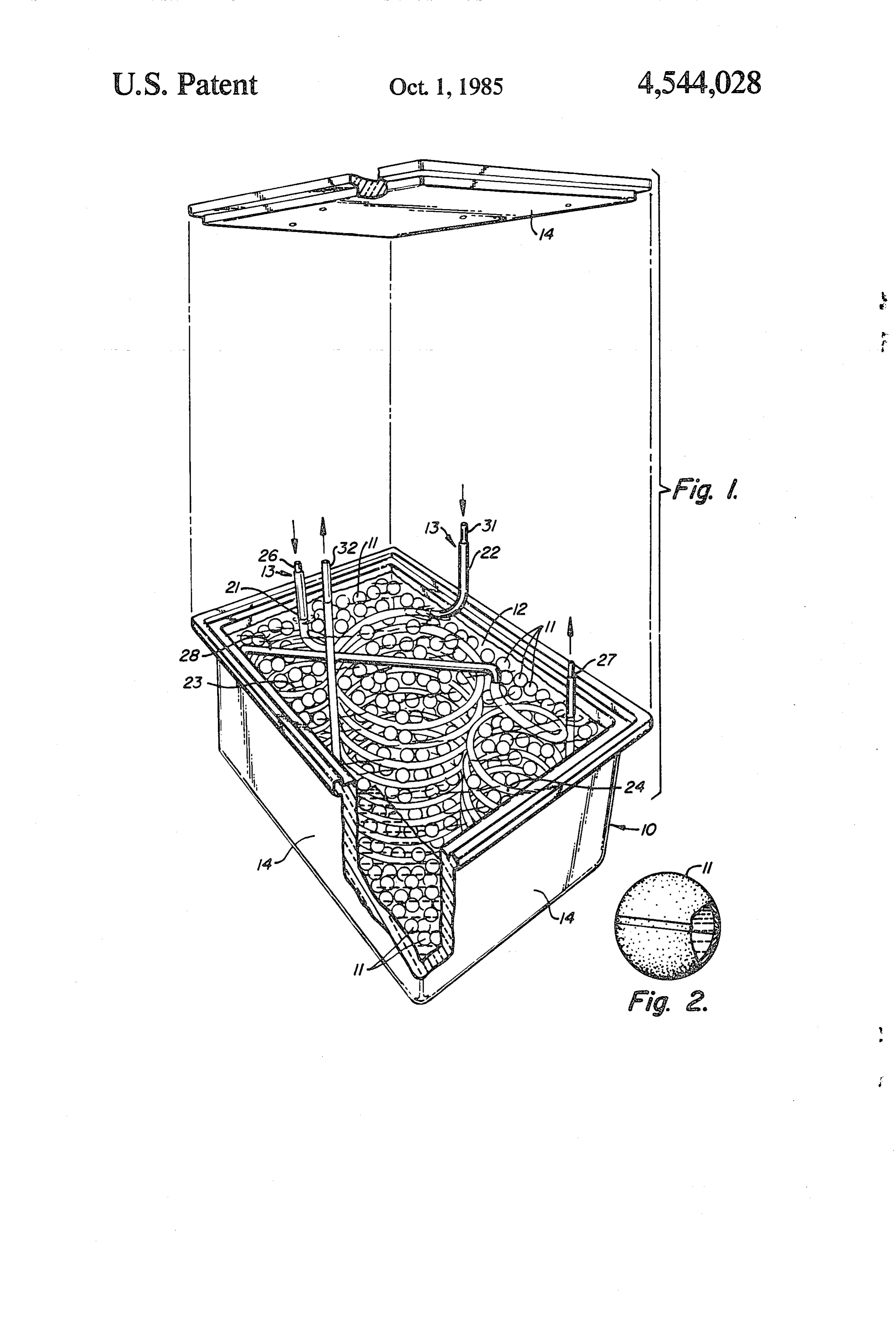
German Offenlegungsschrift No. 2552 698 discloses BRIEF DESCRIPTION OF THE DRAWINGS another heat-storage system in which a large number of hollow heat-storage balls are packed in a regular array FIG. 1 is a cut-away exploded perspective view of a within an insulated container. The balls contain a phase heat-storage apparatus constructed in accordance with change material for the storage of heat. A pipeline sys- 40 the invention; and tem runs through the array in a regular pattern making FIG. 2 is a cut-away elevational view of an individual direct contact with all of the balls of the array. Heat heat-storage element.
transfer with the phase-change material within the balls DETAILED DESCRIPTION OF THE is effected by means of a heat exchange fluid which is PREFERRED EMBODIMENT pumped through the pipeline system. 45 which the large number of balls are disposed within the of the present invention comprises a vessel 10, a plural insulated container in close-packed configuration and ity of heat-storage elements 11 immersed in a heat-trans immersed in a heat-transfer bath. The spaces between fer fluid bath 12 contained in the vessel 10, and means the balls, which are stationarily fixed in their close- 50 for heat exchange with the heat-transfer bath 12. The packed configuration, effectively define convection heat exchange means is generally designated by refer ducts through which the heated bath will rise and circu ence numeral 13. For reasons which will be appreciated late to deliver heat to the phase-change material within more fully hereinbelow, the plurality of heat storage the spherical balls. elements 11 are disposed in loose-packed configuration In all of these heat storage devices the exchange of 55 within the heat transfer bath 12.
heat is impeded by the fact that the heat-storage me The vessel 10 is enclosed on all sides by insulating dium will become fully charged in a localized region in walls 14. Suitable materials for the construction of insu . the vicinity of the heat-transfer means. The heat then lating walls 14 are well known to those skilled in the art. must follow a secondary exchange path, requiring a The heat-storage elements 11 contain a phase-change greater heat exchange time, to reach the regions of 60 material such as a salt hydrate; a hydrate of CaCL2 with heat-storage medium removed from the immediate vi an admixture of impurity, for example, aborate or silica, cinity of the heat transfer means. to provide a nucleation basis for crystallization has been SUMMARY OF THE INVENTION found suitable for this purpose, and other phase-change materials will readily occur to those skilled in the art. It
The present invention provides a heat-storage appa- 65 is characteristic of the invention that heat-storage ele ratus which demonstrates an especially efficient heat ments 11, containing the phase change material, have transfer into and out of the heat-storage medium and essentially zero buoyancy when immersed in heat-trans which allows heat to accumulate in some regions of the fer bath 12. As is well known, the buoyancy of heat 4 storage elements 11 depends on the relative density of In operation, a first service fluid charged with heat an element 11 with respect to the density of the heat from a heat source, for example, a solar panel, enters the transfer bath 12. Those skilled in the art will readily be apparatus through inlet 26 of charging conduit 21. The able to fabricate heat-storage elements 11 with the req service fluid continues downward through the first uisite density. 5 coiled portion 23 to the bottom of vessel 10, whence it Heat-exchange means 13 preferably comprises at least continues upward and through cross conduit 28 to the one conduit formed, for example, by a length of copper upper stage of coiled portion 24. The service fluid trav tubing which extends in a coil or serpentine configura els through this coiled portion from top to bottom and tion through the heat-transfer bath 12. In the best mode then exits the apparatus through outlet 27 and returns to for practicing the invention the heat-exchange means 13 10 the solar panel to be recharged. A second service fluid comprises a first conduit 21 for charging the system for the extraction of heat enters discharge conduit 22 with heat and a second conduit 22 for discharge of heat through inlet 31 and travels from top to bottom through from the system. Charging conduit 21 includes portions been the coiled portion and exits through outlet 32. It has found that the direction of flow through the coiled 23 and 24 which are formed in vertically extending coils 15 portions disposed in diagonally opposed corners of the vessel 10. heat transfer from top to bottom produces more effective Discharge conduit 22 is preferably formed with a single conduit 21 to from bath, the first service fluid in charging 12 and from bath 12 to the second coiled portion larger than the charging coiled portions 23 and 24 and disposed centrally within the vessel 10 service fluid in discharge conduit 22. In the first instance the heat is transferred from the between the charging coil portions 23 and 24. For the service fluid of charging conduit 21 to the bath 12, and best operation of the invention, successive turns of the then to the phase-change material within the heat-stor coiled portions of conduits 21 and 22 should be spread apart a distance larger than the longest dimension of age elements 11. The elements in the vicinity of the charging coiled portions 23 and 24 will be charged first.
heat-storage elements 11, so that an individual heat-stor Because the material in the heat-storage elements 11 age element 11 is able to pass through the sides of the 25 stores heat primarily in the latent heat of transition, as a coiled portions back and forth between the interior and practical matter the charging service fluid need be at a exterior regions thereof. temperature only slightly greater than that of the phase Charging conduit 21 is provided with an inlet 26 change material itself within the heat-storage elements proximate the top of the first vertically extending coiled portion 23 and an outlet 27 communicating directly for effective heat transfer. The discharge service fluid in conduit 22 will initially withdraw heat from those heat with the bottom of the second coiled portion 24. The storage elements in the vicinity of the conduit 22. As two coiled portions 23 and 24 are connected by cross heat is extracted from the storage elements in the vicin conduit 28, which extends horizontally in the upper ity of the discharge conduit 22 and as heat is simulta portion of heat-transfer bath 12. Discharge conduit 22 neously supplied to the storage elements in the vicinity includes an inlet 31 leading to the top of the discharge 35 of the charging conduit 21, storage elements in the conduit coiled portion and an outlet 32 communicating vicinity of the coiled portions 23 and 24 will tend to directly with the bottom of the discharge conduit coiled migrate toward the discharge conduit 22, and vice portion. The inlets and outlets 26, 27, 31, and 32 extend versa. The result is a slow circumferential circulation of through the top wall of vessel 10 and are adapted for heat-storage elements 11, which carries fully charged connection to a heat source and heat sink as dictated by 40 storage elements to the vicinity of the discharge conduit the system with which the heat-storage apparatus is to for discharging and partially or fully discharged storage be used. elements to the vicinity of the charging conduit 21 for It is a characteristic of the invention that the individ recharging. In addition, as discharge service fluid is ual heat-storage elements 11 be free to migrate about circulated through discharge conduit 22, there will be vessel 10. To allow such migration, it is necessary that 45 established a vertical temperature gradient in the vicin fewer heat-storage elements be disposed within vessel ity of the conduit 22. A slow secondary circulation of 10 than could be used, say, if they were disposed in the heat-storage elements will occur in the vertical direc close-packed configurations of U.S. Patent No. tion primarily within the internal region of the coiled 4,111,189 or of German Offenlegungsschrift No. 2552 portion of discharge conduit 22.
698. While it would ordinarily appear less desirable to 50 The primary effect of the induced circulations, in use fewer heat-storage elements, hence, less phase particular, of the circumferential circulation, is to bring change material for storing heat, it is found in the pres the heat-storage elements to the location where they are ent invention to be well worth the tradeoff. The mobile needed the most. A secondary effect is to continually nature of the heat-storage elements achieved by sacrific stir up and mix the phase-change material within the ing a small amount of phase-change material leads to 55 individual heat storage elements. The continual mixing greatly enhanced ability to accumulate heat and extract prevents the phase-change material from becoming heat from the storage elements. frozen in one state or another, thereby providing a To facilitate the ability to migrate, the heat-storage greater lifetime of the individual storage elements and a elements 11 are preferably formed in a generally spheri greater dependability of the heat-storage apparatus as a cal shape. The use of a large number of heat-storage 60 whole. Mixing of the phase-change material brought elements 11, each having a relatively small size, also has about by the characteristic mobility of the heat-storage the advantage that the plurality of heat-storage ele elements also facilitates more complete change of phase ments 11 exposes a comparatively large surface area to of the material within each of the elements 11. That is, the heat-transfer bath 12 for a given volume of phase the mixing facilitates the full capability of the phase change material disposed within vessel 10. The greater 65 change material to store heat.
surface area facilitates heat exchange between the heat In summary, the invention provides a heat-storage transfer bath 12 and the phase change material within apparatus in which the heat is stored in a large number the heat storage elements 11. of comparatively small, mobile, heat-storage elements.
Page 5scan →
By its construction the apparatus induces a slow circula 2. The heat storage apparatus of claim 1, wherein said tion of the individual heat-storage elements, which heat-storage elements are of generally spherical shape serves to equilibrate local regions of fully charged and so as to maximize the quantity of phase-change material partially charged heat-storage elements. The circulation contained therein and to facilitate migration in said of heat-storage elements and the induced mixing of 5 heat-transfer fluid bath.
phase-change material allow for much faster utilization 3. The heat-storage apparatus of claim 1, wherein said of the full heat-storage capacity of a given quantity of charging conduit and said discharge conduit have por phase-change material than has been possible in the past tions formed in vertically extending coil configurations and greatly facilitates the simultaneous charging and So as to enhance convective circulation of said heat discharging of heat to and from different regions of the O storage elements between upper and lower ends of said apparatus. coil portions in response to a vertical temperature gradi While the above provides a full and complete disclo ent across said coil portions produced by hotter or sure of the preferred embodiment of the present inven colder fluid circulating there-through. tion, various modifications, alternate constructions, and 4. The heat-storage apparatus of claim 3, wherein said equivalents may be employed with departing from the 15 charging conduit has two vertically extending coil por true spirit and scope of the invention. For example, tions disposed on opposite sides of the coil portion of given the benefit of this disclosure, vessels of other said discharge conduit.
shapes and other arrangements of heat exchange means 5. The heat-storage apparatus of claim 3, wherein for inducing circulation of heat-storage elements will successive turns of said coil configurations are spread occur to those of ordinary skill in the art. Moreover, 20 apart a distance greater than the longest dimension of although the invention has been illustrated and de said heat-storage elements so as to enable said elements scribed herein in terms of a heat-storage apparatus, to migrate into and out of the interior region of said coil ordinary artisans will readily appreciate that the appara portions.
tus can also be utilized in connection with refrigeration 6. A heat-storage apparatus comprising: systems for extracting heat from a service fluid rather 25 a vessel having insulating walls and containing a heat than for supplying heat to a service fluid as described transfer fluid bath;
above. a plurality of heat-storage elements, each element Therefore, the above description and illustration comprising a hollow container of generally spheri should not be construed as limiting the scope of the cal shape containing a phase-change material, said invention, which is defined by the appended claims. 30 heat-storage elements having substantially zero What is claimed is: buoyancy in said fluid bath; 1. A heat storage apparatus comprising: a charging conduit having a first vertically extending a vessel having insulating walls and containing a heat coil portion proximate a first wall of said vessel and transfer fluid bath; a second vertically extending coil portion proxi a plurality of mobile heat-storage elements containing 35 mate a second wall of said vessel opposite said first a phase-change material, each said heat-storage wall, successive turns of said coil portions being element having substantially zero buoyancy in said spread apart a distance greater than the diameter of fluid bath, said plurality of heat-storage elements said generally spherical container; and being disposed within said fluid bath in sufficiently a discharge conduit having a vertically extending coil loose configuration to allow said heat-storage ele 40 portion disposed between the first and second coil ments to migrate about said vessel; and portions of said charging conduit; a charging conduit and a discharge conduit for con wherein said plurality of heat-storage elements are ducting fluid through said heat-transfer fluid bath, disposed within said heat-transfer fluid bath suffi said conduits being spaced apart from one another ciently loosely to allow said heat-storage elements within said fluid bath, whereby said heat-storage 45 to migrate about said vessel in response to ther elements are free to migrate between hotter and mally induced convective circulation in said heat cooler regions of said heat-transfer fluid bath for transfer fluid bath.
the transfer of heat therewith. k ck ck ck k
Provenance
- Collection
- Patents citing this work
- Pages
- 5
- Method
- pdftotext (the PDF's own text layer) + pdftoppm 300dpi page scans
- Patent office record
- patents.google.com →
- Source
- Google Patents citing-documents table
- Assignee
- C. Mitchell Bedford
- Published
- 1985-10-01
- Transcribed from
- patentimages.storage.googleapis.com →